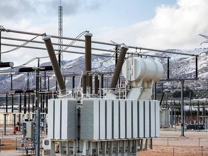
Power transformers are essential devices in electrical power systems, enabling the safe and efficient transmission of electricity across vast distances. But how do they actually work? At their core, power transformers operate on electromagnetic principles to convert voltage levels while maintaining energy integrity. This article breaks down the working mechanism of a power transformer into simple and clear sections.
What Is the Basic Principle Behind a Power Transformer?
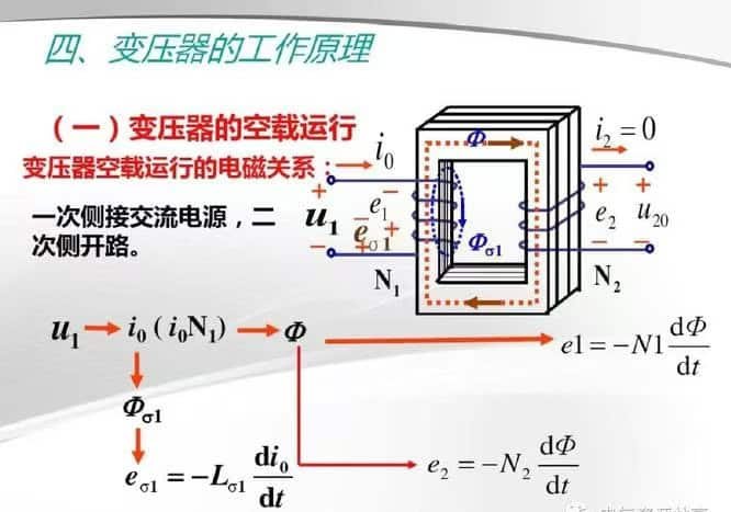
Power transformers are essential to modern electrical infrastructure, but how do they actually work? At the heart of every transformer is a fundamental physical principle that’s been harnessed for over a century: electromagnetic induction. This simple but powerful concept allows transformers to efficiently change voltage levels without any moving parts, making them ideal for high-reliability, high-efficiency energy transfer in the power grid. Understanding the basic principle behind a power transformer reveals how such a silent, static device plays such a dynamic role in electricity distribution.
The basic principle behind a power transformer is electromagnetic induction, where a changing magnetic field in the transformer's core induces a voltage in its secondary winding. When alternating current flows through the primary winding, it creates a magnetic field that links with the secondary winding, allowing voltage to be increased or decreased based on the ratio of turns in the windings.
This allows safe and efficient voltage conversion without direct electrical contact between circuits.
Power transformers operate based on electromagnetic induction, which enables voltage change through magnetic coupling between windings.True
The primary winding generates a magnetic field that induces voltage in the secondary winding without a direct electrical connection.
Power transformers work by mechanically increasing current flow through gears and motors.False
Transformers have no moving parts; they work entirely through magnetic fields and electromagnetic induction.
Core Components and Their Functions
| Component | Function |
|---|---|
| Primary Winding | Receives the input alternating voltage from the power source |
| Magnetic Core | Channels the magnetic flux between primary and secondary coils |
| Secondary Winding | Delivers the output voltage based on winding ratio |
| Insulation | Electrically separates and protects windings and core |
| Enclosure/Tank | Houses components; often filled with oil for cooling and insulation |
These elements form a non-contact system where energy is transferred magnetically.
Step-by-Step: How a Power Transformer Works
AC Voltage Applied to Primary Coil
- Alternating current produces a changing magnetic field in the transformer core.
Magnetic Flux in Laminated Core
- The magnetic field circulates through the iron core, linking the secondary coil.
Induced Voltage in Secondary Coil
- According to Faraday’s Law of Electromagnetic Induction, a changing magnetic field induces a voltage in the secondary coil.
Voltage Ratio Determined by Turn Ratio
- If the secondary has more turns than the primary, voltage is increased (step-up).
- If the secondary has fewer turns, voltage is decreased (step-down).
Voltage Conversion Formula
$$\frac{V_s}{V_p} = \frac{N_s}{N_p}$$
Where:
- $V_s$ = Secondary Voltage
- $V_p$ = Primary Voltage
- $N_s$ = Number of Turns in Secondary
- $N_p$ = Number of Turns in Primary
| Winding Configuration | Result |
|---|---|
| $N_s > N_p$ | Step-Up Transformer |
| $N_s < N_p$ | Step-Down Transformer |
| $N_s = N_p$ | Isolation Transformer |
Efficiency of Power Transformers
Power transformers are extremely efficient, often achieving:
| Load Condition | Typical Efficiency |
|---|---|
| 50% Load | 98.2–98.8% |
| 100% Load | 98.5–99.3% |
Efficiency is enhanced by using high-grade core materials, precise winding geometry, and low-resistance conductors.
Why Alternating Current (AC) is Essential
- Transformers only work with AC, because DC produces no changing magnetic field, and thus no induced voltage.
- This is why electrical grids around the world use alternating current systems, allowing transformers to function across generation, transmission, and distribution.
Real-World Example
Step-Down Transformer at a Distribution Substation:
- Input (Primary): 132kV
- Output (Secondary): 33kV
- Turn Ratio: 4:1
- Function: Prepares voltage for final delivery to urban districts
This simple ratio-based operation, based on magnetic coupling and precise winding counts, powers entire cities.
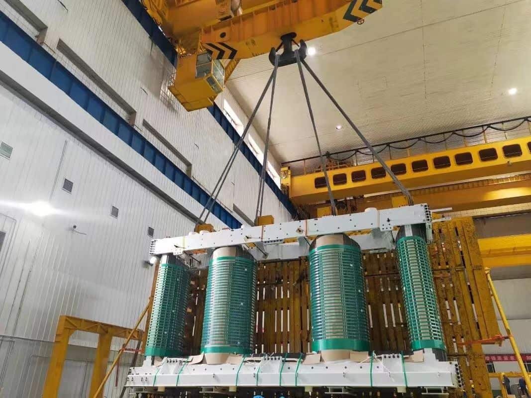
How Do the Primary and Secondary Windings Function?
At the heart of every transformer lies its two most essential components: the primary and secondary windings. These windings are not just lengths of coiled wire—they are precision-engineered elements that enable electromagnetic energy transfer between circuits. Through the process of electromagnetic induction, these coils interact without ever touching, allowing voltage to be increased or decreased without a direct electrical connection. This makes transformers extremely efficient, electrically isolated, and safe for converting power across the electrical grid.
The primary winding receives input alternating current (AC) from the power source, creating a magnetic field in the transformer's core. This magnetic field links to the secondary winding, where it induces a new voltage according to the number of coil turns. The voltage change between the primary and secondary windings is determined by their turn ratio, enabling step-up or step-down transformation.
This non-contact interaction enables power transfer with high efficiency and electrical isolation.
The primary winding receives input power and generates a magnetic field, while the secondary winding produces the transformed output voltage.True
The primary coil's alternating current generates magnetic flux, which induces voltage in the secondary coil based on turn ratio.
The primary and secondary windings are connected directly by conductors to transfer electricity.False
There is no direct electrical connection between the windings; energy is transferred magnetically through the transformer core.
Step-by-Step Function of Windings in a Transformer
| Stage | Action |
|---|---|
| 1. Primary Winding Energized | Alternating voltage applied; AC current flows |
| 2. Magnetic Field Created | Alternating current generates changing magnetic flux in the iron core |
| 3. Flux Links Secondary | Magnetic flux flows through the laminated core to the secondary coil |
| 4. Voltage Induced | AC voltage induced in secondary winding by electromagnetic induction |
| 5. Power Output | Secondary supplies power at new voltage level to load (stepped up or down) |
The entire process depends on AC voltage and Faraday's Law of Induction.
Faraday’s Law in Action
$$\text{Induced Voltage (E)} = -N \cdot \frac{d\Phi}{dt}$$
Where:
- $E$ = Induced voltage
- $N$ = Number of turns
- $\frac{d\Phi}{dt}$ = Rate of change of magnetic flux
More turns = more induced voltage; this is why turn ratio determines whether the transformer increases or decreases voltage.
Primary vs Secondary Windings: Key Differences
| Feature | Primary Winding | Secondary Winding |
|---|---|---|
| Connection | Connected to AC power source | Connected to the load/output circuit |
| Function | Creates magnetic field via AC input | Receives induced voltage through magnetic flux |
| Turn Count (Step-Up) | Fewer turns | More turns |
| Turn Count (Step-Down) | More turns | Fewer turns |
| Voltage Role | Input voltage | Output voltage (higher/lower depending on ratio) |
Common Transformer Turn Ratios
| Use Case | Voltage In (Primary) | Voltage Out (Secondary) | Turn Ratio (Ns\:Np) |
|---|---|---|---|
| Power Transmission (Step-Up) | 11kV | 132kV | 12:1 |
| Local Substation (Step-Down) | 132kV | 33kV | 1:4 |
| Pole-Mount Transformer | 11kV | 400V | 1:27.5 |
Turn ratio is the engineering key to transformer voltage behavior.
Insulation and Isolation in Windings
- Windings are insulated with enamel coatings, paper, resin, or oil-immersed barriers.
- There is no direct electrical contact between primary and secondary.
- This ensures galvanic isolation, protecting circuits and preventing fault propagation.
Real-World Transformer Example
250 kVA Distribution Transformer
- Primary winding: 11kV (≈ 10 turns per layer, copper)
- Secondary winding: 415V (≈ 275 turns total)
- Core: CRGO silicon steel laminated for low loss
- Cooling: Oil-immersed (ONAN), to remove heat from windings
This setup provides continuous, efficient power to dozens of households or a small commercial block.
Efficiency of Winding-Based Energy Transfer
| Metric | Typical Value |
|---|---|
| Efficiency (Full Load) | 98.5–99.3% |
| Voltage Regulation Accuracy | ±1–2% |
| Power Factor Compatibility | >0.95 |
| Load Carrying Capacity | Up to 1,000 MVA |
Efficient windings = efficient power transfer, even at industrial scale.
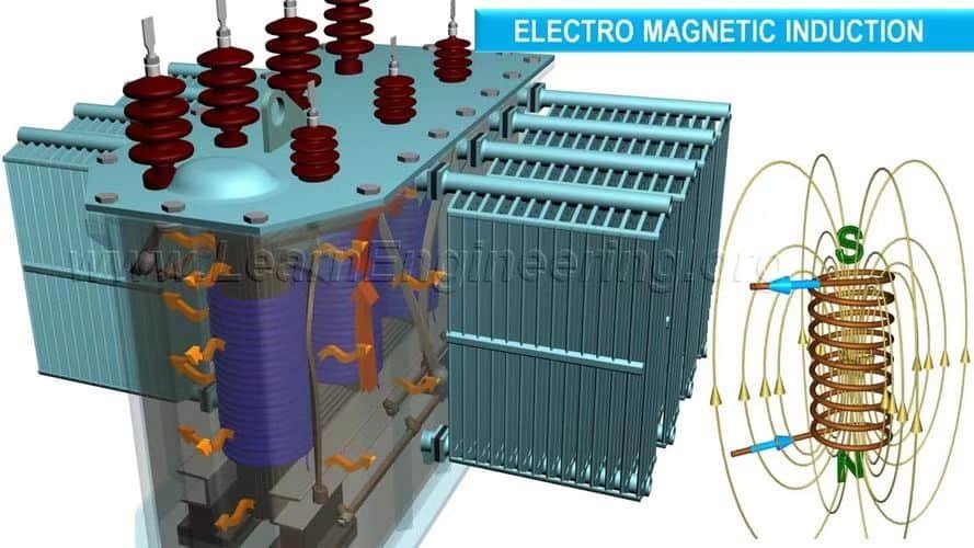
What Role Does the Magnetic Core Play in Energy Transfer?
At the heart of every power transformer lies a magnetic core—the silent, unmoving medium that enables high-efficiency energy transfer between the primary and secondary windings. While the windings carry electrical current, it’s the magnetic core that links them, acting as the conductor for the magnetic field necessary for induction. Without it, transformers would lose their efficiency and effectiveness. The core ensures that electromagnetic energy is transferred precisely, with minimal loss, even at very high voltages or heavy loads.
The magnetic core in a power transformer functions as the path for magnetic flux created by the primary winding, allowing efficient electromagnetic induction in the secondary winding. It concentrates and guides the magnetic field between the windings, ensuring minimal energy loss and high transfer efficiency. Without the core, the coupling between windings would be weak, leading to poor voltage transformation and excessive losses.
The core turns fluctuating electric current into usable power by directing magnetic energy between circuits.
The magnetic core enables electromagnetic induction between the primary and secondary windings, ensuring efficient energy transfer.True
The core guides the magnetic flux created by the primary winding so it links effectively with the secondary winding, enabling voltage transformation.
The magnetic core generates electrical power in the transformer directly.False
The core does not generate power—it only serves to channel the magnetic field created by the primary coil to the secondary.
What Is a Magnetic Core?
| Component | Description |
|---|---|
| Material | Cold-rolled grain-oriented (CRGO) silicon steel or amorphous alloy |
| Construction | Laminated sheets stacked to form a closed loop (core-type or shell-type) |
| Purpose | Provide a low-reluctance path for alternating magnetic flux |
| Shape Types | E-core, toroidal, shell, or core-type transformers |
The core is not powered, but it is the functional medium for magnetic coupling.
The Role of the Magnetic Core in Energy Transfer
Flux Carrier
- When AC flows in the primary coil, a magnetic field is generated.
- The core confines and channels this field through its high magnetic permeability.
Coupling Mechanism
- The magnetic field induced in the core links with the secondary winding, producing voltage via induction.
Loss Minimization
- Compared to air, the core reduces magnetic reluctance and keeps the magnetic circuit efficient.
- Laminations prevent eddy current formation, reducing heating and core loss.
Energy Transfer Process Illustrated
| Stage | Role of Core |
|---|---|
| Primary current flows | AC current generates alternating magnetic flux in the core |
| Flux loops through core | Magnetic lines of force circulate through laminated path |
| Secondary winding linked | Flux induces voltage in secondary winding via mutual induction |
The core acts as a bridge of magnetic energy, enabling contactless power transmission.
Why Laminated Steel?
| Problem | Core Design Solution |
|---|---|
| Eddy current losses | Laminations reduce circulating current and resistive heating |
| Magnetic hysteresis loss | CRGO steel minimizes core loss due to molecular alignment |
| Heating and vibration | Precision stacking and clamping control thermal expansion |
These features help maintain >98.5% transformer efficiency under full load conditions.
Types of Magnetic Cores
| Core Type | Shape | Application |
|---|---|---|
| Core-Type | Rectangular E-I core | Most common in distribution/power transformers |
| Shell-Type | Central core enclosed by windings | Used for better magnetic shielding and short-circuit strength |
| Toroidal | Ring-shaped | Compact dry-type or specialty transformers |
| Amorphous Core | Thin, non-crystalline alloy | Ultra-low loss for high-efficiency green applications |
Real-World Example: Medium Voltage Power Transformer
| Core Material | CRGO Silicon Steel |
|---|---|
| Core Configuration | 3-leg, stacked laminated core (core-type) |
| Power Rating | 11kV / 0.415kV, 630 kVA |
| Efficiency | >98.6% |
| No-Load Loss | < 0.3% of rated power |
The core ensures magnetic flux remains confined, preventing field leakage and efficiency loss.
Magnetic Core and Efficiency
| Factor | Effect on Efficiency |
|---|---|
| High Permeability | Less magnetizing current needed |
| Thin Lamination | Reduces eddy currents |
| Proper Core Design | Reduces core saturation under load |
| Low Core Loss Material | Saves energy even when transformer is unloaded |
Core design directly influences both no-load losses and thermal behavior.
How Is Voltage Increased or Decreased in a Transformer?
Transformers are the backbone of modern power systems, and their core function is voltage conversion. Whether it's stepping up voltage for efficient long-distance transmission or stepping it down for safe residential use, transformers handle this seamlessly—all without moving parts. The magic lies in their turn ratio, which determines how much voltage is increased or decreased between the input (primary) and the output (secondary) windings. Understanding this process is essential to appreciating how electricity flows safely and efficiently from generation plants to the devices in your home.
Voltage is increased or decreased in a transformer based on the ratio of turns between the primary and secondary windings. If the secondary winding has more turns than the primary, the transformer steps up the voltage; if it has fewer turns, the transformer steps it down. This voltage transformation occurs through electromagnetic induction, where alternating current in the primary coil induces a proportional voltage in the secondary coil.
The turn ratio is the key that unlocks the desired voltage transformation.
Transformers increase or decrease voltage using the ratio of turns between the primary and secondary windings.True
The voltage is proportional to the number of turns in each winding; more turns in the secondary increase voltage, fewer reduce it.
Transformers change voltage using motors or mechanical gears inside the core.False
Transformers have no moving parts; voltage change is achieved purely through electromagnetic induction and winding ratios.
Fundamental Voltage Ratio Formula
$$\frac{V_s}{V_p} = \frac{N_s}{N_p}$$
Where:
- $V_s$ = Secondary Voltage
- $V_p$ = Primary Voltage
- $N_s$ = Number of turns in secondary winding
- $N_p$ = Number of turns in primary winding
| Turn Ratio | Resulting Action |
|---|---|
| $N_s > N_p$ | Step-Up Transformer |
| $N_s < N_p$ | Step-Down Transformer |
| $N_s = N_p$ | Isolation Transformer |
Step-Up Transformers: Increasing Voltage
Use Case:
- Power generation station: 11kV output from generators
- Voltage stepped up to 132kV or 400kV for transmission
| Primary Turns | Secondary Turns | Effect |
|---|---|---|
| 100 | 1200 | 11kV → 132kV (×12 increase) |
High voltage = low current, which means reduced energy loss over long distances.
Step-Down Transformers: Decreasing Voltage
Use Case:
- Local distribution: 11kV feeder stepped down to 400V/230V for homes and offices
| Primary Turns | Secondary Turns | Effect |
|---|---|---|
| 1100 | 40 | 11kV → 400V (×27.5 decrease) |
Low voltage = safe for consumer use, compatible with lighting, electronics, and appliances.
Visual Representation: Voltage Conversion in the Grid
| Grid Level | Voltage | Transformer Action |
|---|---|---|
| Power Plant Output | 11–25kV | Stepped up to 132–765kV |
| High-Voltage Transmission | 132–765kV | Efficient long-distance transfer |
| Substation | 132–33kV | Stepped down for regional distribution |
| Distribution Transformer | 11kV → 400V/230V | Final voltage reduction for users |
Transformer Operation Example
Scenario: 500 kVA transformer
| Configuration | Input Voltage | Output Voltage | Turns Ratio |
|---|---|---|---|
| Step-Up | 11kV | 132kV | 1:12 |
| Step-Down | 33kV | 11kV | 3:1 |
| Isolation | 400V | 400V | 1:1 |
One transformer, three modes—voltage control by design, not machinery.
Design Factors Affecting Voltage Change
| Parameter | Effect |
|---|---|
| Number of Turns | Determines voltage ratio and conversion capacity |
| Core Material | Affects magnetic flux linkage and efficiency |
| Load Type | Determines voltage regulation requirements (stable or variable) |
| Insulation Class | Ensures safe operation at different voltage levels |
| Cooling System | Maintains temperature and performance during conversion |
Why Voltage Conversion Matters
| Benefit | Enabled by Voltage Change via Transformers |
|---|---|
| Efficient Transmission | High voltage reduces I²R losses |
| Safety at End-User Level | Low voltage prevents shock hazards and equipment damage |
| Infrastructure Compatibility | Appliances and machines designed for 230V/400V usage |
| Load Matching | Adapts grid power to application-specific voltage levels |
No transformer = no safe or efficient voltage compatibility.
What Are the Main Components Involved in Transformer Operation?
Transformers may seem like simple, silent boxes, but inside them lies a network of carefully engineered components working together to transfer energy, manage voltage, and protect systems from electrical failure. Whether for stepping up voltage at a power station or stepping it down for a commercial building, transformers rely on a combination of electromagnetic and mechanical components to perform their function efficiently and safely. To understand how transformers operate, we must look inside and examine the main components that make power transfer possible.
The main components involved in transformer operation are the core (which carries magnetic flux), the primary and secondary windings (which transfer electrical energy), the insulation system (which prevents electrical failure), the tank and bushings (which house and connect the internal parts), the cooling system (which maintains operating temperature), and optional tap changers (which regulate voltage). Each component plays a specific role in ensuring efficient, safe, and reliable transformer performance.
These components form the backbone of the transformer's function—from electromagnetic induction to system protection.
Transformers operate using key components like windings, a magnetic core, insulation, cooling systems, and protective accessories.True
Each component is designed to perform a distinct function, ensuring voltage conversion, energy transfer, and safe operation.
Transformers work purely by electricity flowing through a single wire without any need for additional components.False
Transformers require a magnetic circuit, electrical insulation, cooling systems, and structural parts to function effectively and safely.
Overview of Core Transformer Components
| Component | Primary Function |
|---|---|
| Core | Carries magnetic flux between windings |
| Primary Winding | Receives input voltage from the power source |
| Secondary Winding | Delivers transformed voltage to the load |
| Insulation System | Electrically isolates conductors to prevent arcing and failure |
| Tank/Enclosure | Houses core and windings; filled with oil or air for protection |
| Cooling System | Maintains operating temperature |
| Bushings | Allow external electrical connections through the tank wall |
| Tap Changer | Adjusts voltage ratios during operation |
| Breather/Conservator | Regulates air/oil balance and prevents moisture ingress |
| Protection Devices | Detect faults and ensure safe shutdown |
These parts work in electromechanical harmony to support continuous voltage conversion.
1. Magnetic Core
- Typically made of laminated CRGO steel or amorphous metal
- Directs the magnetic flux between windings
- Minimizes core losses (hysteresis + eddy current)
Acts as the magnetic highway connecting input and output coils.
2. Primary and Secondary Windings
| Primary Winding | Connected to the incoming voltage source (e.g., 11kV) |
|---|---|
| Secondary Winding | Connected to the output circuit (e.g., 400V or 132kV) |
- Made of copper or aluminum for conductivity
- Carefully wound to control voltage ratio, insulation, and current flow
3. Insulation System
- Prevents electrical short circuits between windings or core
- Uses paper, resin, varnish, pressboard, or oil
- Ensures safety under high dielectric stress
Insulation is the invisible shield maintaining internal integrity.
4. Tank and Bushings
- The transformer tank holds oil-immersed components
- Bushings act as insulated terminals for HV/LV connections
- Often grounded and pressure-resistant
| Type | Material | Function |
|---|---|---|
| Oil-filled tank | Mild steel | Protection, cooling, and insulation |
| HV Bushings | Porcelain/resin | Safe connection of high-voltage lines |
5. Cooling System
| Cooling Method | Description | Use Case |
|---|---|---|
| ONAN | Oil Natural Air Natural (passive cooling) | Distribution transformers |
| ONAF | Oil Natural Air Forced (fans added) | Larger power transformers |
| OFAF/OFWF | Oil or water forced flow | High-capacity and substation units |
| Dry-Type | Air cooled or resin encapsulated | Indoor/commercial installations |
Prevents overheating, which can degrade insulation and reduce transformer life.
6. Tap Changer (OLTC/DETC)
- Adjusts transformer output to compensate for voltage drops
- OLTC: On-load tap changer (active adjustment while energized)
- DETC: De-energized tap changer (manual adjustment when offline)
| Function | Impact |
|---|---|
| Tap ±5–20% | Stabilizes voltage during grid fluctuations |
| Multiple steps | Customizes for load or feeder differences |
7. Conservator Tank & Breather
- Conservator tank allows for oil expansion/contraction
- Silica gel breather removes moisture from air entering the tank
- Maintains oil dielectric quality and pressure balance
8. Protection and Monitoring Devices
| Device | Purpose |
|---|---|
| Buchholz Relay | Detects internal arcing or gas generation |
| Temperature Sensor | Monitors winding/oil temp for overheating |
| Pressure Relief Valve | Releases excess pressure to prevent tank rupture |
| Oil Level Indicator | Signals if there's a leak or oil shortage |
| Smart Monitors (IoT) | Enables predictive maintenance and remote alerts |
These components guard the transformer against internal faults and external anomalies.
How Does Transformer Efficiency Remain High During Operation?
Power transformers are expected to operate continuously for decades—often under full load, exposed to extreme environmental conditions, and critical to uninterrupted power supply. Despite these demands, most transformers maintain exceptionally high efficiency—typically 98.5% to 99.3%. This is possible thanks to a combination of intelligent design, superior materials, and optimized operating practices. Understanding how transformer efficiency remains high can help power engineers, utility planners, and facility managers ensure maximum return on investment and energy savings.
Transformer efficiency remains high during operation by minimizing core losses (no-load losses) and copper losses (load losses), using high-grade core materials, precision winding designs, effective cooling systems, and maintaining ideal loading conditions. Innovations in insulation, lamination, oil treatment, and on-load tap changers also help reduce energy waste and preserve performance over time.
These elements ensure that nearly all the energy entering the transformer is delivered to the load with minimal dissipation.
Power transformers maintain high efficiency by reducing both core and copper losses through advanced materials and optimized design.True
Low-loss cores, quality windings, proper cooling, and precise voltage control all contribute to energy-efficient operation.
Transformer efficiency drops drastically during normal operation due to heat and electromagnetic loss.False
Modern power transformers are engineered to minimize losses, often achieving efficiencies above 98.5% even under full load.
Types of Transformer Losses Affecting Efficiency
| Loss Type | Also Known As | Occurs In | Can Be Reduced By |
|---|---|---|---|
| Core Loss | No-Load Loss | Magnetic core | CRGO or amorphous cores, thin laminations |
| Copper Loss | Load Loss | Windings | Larger conductor cross-section, low-resistance copper |
| Stray Loss | Leakage-induced loss | Tank walls and structures | Optimized core design and shielding |
| Dielectric Loss | Insulation-related | Oil and solid insulators | High-quality oil, dry-type insulation systems |
| Cooling Losses | Mechanical and fluid | Fans, pumps | Using natural convection systems or efficient fans |
Efficiency = Output Power / Input Power × 100%, and minimizing these losses keeps that ratio near ideal.
High-Efficiency Design Practices
1. Core Material Selection
- Use CRGO (Cold Rolled Grain Oriented) steel or amorphous metal cores for ultra-low hysteresis and eddy current loss
- Lamination thickness < 0.3 mm to cut eddy current paths
2. Precision Winding Design
- Copper or aluminum conductors with larger cross-sectional areas to reduce resistance
- Shorter winding lengths and tight winding geometry for minimal losses
3. Optimal Cooling Systems
- ONAN (Oil Natural Air Natural) or ONAF (Oil Natural Air Forced) systems to maintain low operating temperatures
- Heat exchangers and radiators designed for steady load conditions
4. Tap Changer for Voltage Control
- On-load tap changers (OLTCs) ensure voltage remains within ideal range
- Prevents overvoltage that increases losses and insulation stress
5. Proper Sizing and Loading
- Transformers sized for 75–100% loading efficiency
- Undersized transformers overheat; oversized ones incur higher no-load losses
Typical Efficiency Across Load Levels
| Load Level (%) | Efficiency Range (%) |
|---|---|
| 25% | 96.5–97.8% |
| 50% | 98.0–98.7% |
| 75% | 98.5–99.1% |
| 100% | 98.7–99.3% |
Transformers perform most efficiently at 75–100% of their rated capacity.
Real-World Efficiency Example: 2500 kVA Substation Transformer
| Parameter | Specification |
|---|---|
| Rated Voltage | 33kV / 11kV |
| Efficiency @ 100% Load | 98.9% |
| Core Loss (No-Load) | 2.2 kW |
| Copper Loss (Full Load) | 18.0 kW |
| Cooling Type | ONAF |
| OLTC Range | ±10% in 1.25% steps |
Despite converting over 2.5 MVA of power, losses are kept under 0.8%, thanks to efficient core and winding design.
Maintenance Practices That Preserve Efficiency
| Maintenance Activity | Impact on Efficiency |
|---|---|
| Oil testing and treatment | Prevents dielectric breakdown, reduces heat |
| Thermal scanning | Detects hotspots before insulation degrades |
| Tap changer servicing | Maintains voltage stability and reduces stress |
| Dust and debris removal | Improves heat dissipation and airflow |
| Periodic load analysis | Confirms transformer is operating in optimal range |
Regular maintenance not only extends life but also prevents hidden losses from degrading performance.
Efficiency Standards and Benchmarks
| Standard | Target Efficiency | Transformer Class |
|---|---|---|
| IEC 60076-1 | ≥98.5% (distribution) | Dry and oil-filled transformers |
| DOE 2016 (USA) | Tier I: ≥98.4% (≥500 kVA) | Liquid-immersed |
| IS 1180 (India) | Star Label Efficiency (Level 3: Highest) | Distribution transformers |
| EU Ecodesign | Tier 2 mandates from 2021 | ≤0.75% total loss (per rating) |
Regulatory compliance ensures minimum energy waste and long-term economic benefit.
Conclusion
A power transformer works by using electromagnetic induction to transfer energy between two or more windings without direct electrical connection. It adjusts voltage levels to meet the needs of transmission or distribution. The transformer’s core, windings, and insulation systems work together to ensure minimal losses and long-term reliability. Understanding how it works reveals why it is such a cornerstone of modern power infrastructure.
FAQ
Q1: How does a power transformer work?
A1: A power transformer works on the principle of electromagnetic induction. It transfers electrical energy between two circuits by converting voltage levels. It has two main windings—primary and secondary—wrapped around a magnetic core. When AC flows through the primary winding, it generates a magnetic field, which induces a voltage in the secondary winding. The voltage changes depending on the turn ratio between the windings.
Q2: What are the main parts of a power transformer?
A2: Key components include:
Primary winding: Receives input voltage
Secondary winding: Delivers transformed voltage
Magnetic core: Provides a path for magnetic flux
Cooling system: Dissipates heat (oil or air)
Tap changer: Adjusts voltage levels
Bushing terminals: Connect transformer to external circuits
Q3: What is the difference between step-up and step-down transformers?
A3:
A step-up transformer increases voltage from primary to secondary side (used at power plants for transmission).
A step-down transformer decreases voltage from primary to secondary side (used at substations and for distribution to end users).
Q4: Why is AC (Alternating Current) essential for transformer operation?
A4: Transformers only work with AC because changing current is needed to create a changing magnetic field, which in turn induces voltage in the secondary coil. DC (Direct Current) does not create the varying magnetic field necessary for induction.
Q5: How does a power transformer ensure energy efficiency?
A5: Power transformers are designed with high-quality core materials, low-resistance windings, and efficient cooling systems to minimize losses. They typically achieve efficiencies of 98–99%, especially under full-load conditions.
References
"How Power Transformers Work" – https://www.transformertech.com/how-power-transformer-works – Transformer Tech
"Working Principle of a Transformer" – https://www.electrical4u.com/working-principle-of-transformer – Electrical4U
"Understanding Power Transformer Operation" – https://www.powermag.com/transformer-working-explained – Power Magazine
"Electromagnetic Induction in Transformers" – https://www.sciencedirect.com/electromagnetic-induction-transformers – ScienceDirect
"Smart Grid News: Transformer Technology Explained" – https://www.smartgridnews.com/transformer-operation-basics – Smart Grid News
"Energy Central: Anatomy of a Transformer" – https://www.energycentral.com/c/ee/power-transformer-components – Energy Central
"ResearchGate: Transformer Magnetic Core Behavior" – https://www.researchgate.net/transformer-core-operation – ResearchGate
"PowerGrid: Step-by-Step Guide to Transformer Operation" – https://www.powergrid.com/transformer-working-principle – PowerGrid