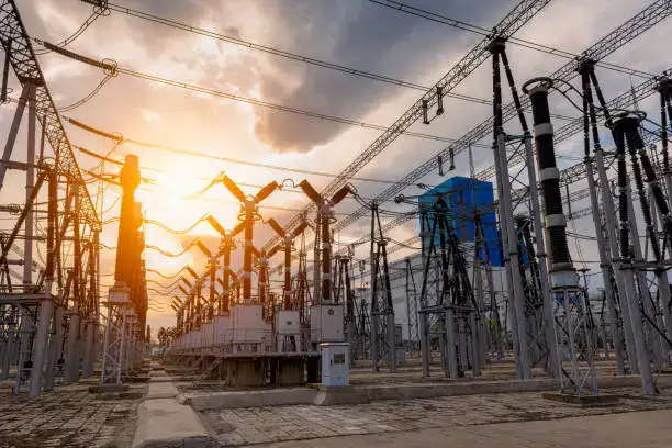
Power transformers are critical components in electrical power systems, enabling the efficient transmission and distribution of electricity over long distances. They function by changing the voltage levels in an alternating current (AC) supply, making power suitable for different stages of power distribution and usage. Understanding how power transformers work is key to appreciating their vital role in modern electricity networks.
What Is the Basic Principle Behind Transformer Operation?
Transformers are essential to modern power systems because they can change voltage levels efficiently, safely, and reliably without any moving parts. Although their construction appears simple, their operation is based on a fundamental physical principle that allows electrical energy to be transferred from one circuit to another with high efficiency and electrical isolation.
The basic principle behind transformer operation is electromagnetic induction, where an alternating current in one winding creates a changing magnetic field that induces a voltage in another winding through a shared magnetic core. This principle allows energy transfer without direct electrical contact or mechanical motion.
Transformer operation is based on electromagnetic induction rather than mechanical or direct electrical coupling.True
A time-varying magnetic field produced by alternating current induces voltage in another winding according to Faraday’s Law.
Role of Alternating Current
Transformers operate only with alternating current (AC). When AC flows through the primary winding:
- The current continuously changes in magnitude and direction
- A time-varying magnetic field is produced
- This changing magnetic field is essential for inducing voltage
Direct current (DC) cannot sustain transformer operation because it produces a constant magnetic field that does not induce continuous voltage.
Creation of Magnetic Flux
The alternating current in the primary winding generates magnetic flux. This flux:
- Flows through the magnetic core
- Links both primary and secondary windings
- Forms the energy transfer path
The magnetic core provides a low-reluctance path, concentrating the flux and minimizing losses.
Induction of Voltage in the Secondary Winding
According to Faraday’s Law:
- A changing magnetic flux induces an electromotive force (voltage)
- The induced voltage depends on the rate of flux change and number of turns
As a result:
- Voltage appears at the secondary terminals
- No direct electrical connection exists between windings
- Electrical isolation is maintained
Voltage Transformation by Turns Ratio
The ratio of voltages between primary and secondary windings is determined by their turns ratio:
- More turns result in higher voltage
- Fewer turns result in lower voltage
This allows transformers to step voltage up or down precisely for transmission and distribution.
Energy Balance Under Load
When a load is connected to the secondary:
- Secondary current flows
- The magnetic balance changes
- The primary automatically draws more current
This ensures that input power matches output power plus losses, maintaining stable operation.
No Mechanical Motion Required
Because energy transfer occurs through electromagnetic fields:
- No moving parts are needed
- Mechanical wear is eliminated
- Reliability and service life are greatly enhanced
This is why transformers can operate continuously for decades with minimal maintenance.
How Does Electromagnetic Induction Enable Voltage Transformation?
Voltage transformation is one of the most critical functions in electrical power systems, allowing electricity to be transmitted efficiently over long distances and safely used by end equipment. This capability does not rely on mechanical gearing or electronic conversion but on a fundamental physical process that operates silently and continuously inside a transformer.
Electromagnetic induction enables voltage transformation by using a time-varying magnetic field, created by alternating current in the primary winding, to induce a proportional voltage in the secondary winding according to the turns ratio between the windings. This process allows voltage to be increased or decreased without direct electrical contact or energy conversion losses associated with mechanical systems.
Voltage transformation in a transformer is achieved through electromagnetic induction and winding turns ratio.True
A changing magnetic flux induces voltage in each winding, and the voltage magnitude is proportional to the number of turns linked to the flux.
Creation of Inducing Magnetic Flux
When an alternating voltage is applied to the primary winding:
- Alternating current flows through the winding
- A time-varying magnetic field is produced
- Magnetic flux is established in the transformer core
The continuous change in magnetic flux is the essential requirement for electromagnetic induction.
Flux Linkage With Multiple Windings
The magnetic core guides the flux so that it links both the primary and secondary windings:
- The same magnetic flux passes through all windings
- Flux magnitude is nearly constant under normal operation
- Energy transfer is magnetically coupled
This shared magnetic environment allows voltage to be induced in multiple windings simultaneously.
Faraday’s Law and Induced Voltage
According to Faraday’s Law of Electromagnetic Induction:
- The induced voltage in a winding is proportional to the rate of change of magnetic flux
- It is also proportional to the number of turns in that winding
Mathematically, this means:
- More turns → higher induced voltage
- Fewer turns → lower induced voltage
This relationship is the foundation of voltage transformation.
Role of Turns Ratio
Voltage transformation occurs because different windings have different numbers of turns:
- Step-up transformer: secondary has more turns than primary
- Step-down transformer: secondary has fewer turns than primary
The voltage ratio follows directly from the turns ratio, enabling precise control of output voltage.
Energy Conservation During Voltage Change
Although voltage changes, total power remains balanced:
- Increasing voltage reduces current proportionally
- Decreasing voltage increases current proportionally
- Input power equals output power plus losses
Electromagnetic induction ensures this balance automatically without control circuitry.
Electrical Isolation and Safety
Electromagnetic induction allows voltage transformation without electrical contact:
- Primary and secondary circuits are galvanically isolated
- Faults are contained within one side
- Equipment and personnel safety is enhanced
This isolation is a major advantage over direct electrical connections.
Stability Across Load Conditions
When load conditions change:
- Secondary current changes accordingly
- Primary current adjusts to maintain magnetic flux
- Voltage transformation remains stable
The induction process is self-regulating and highly reliable.
Why Frequency Matters
Voltage transformation depends on the rate of flux change:
- Higher frequency increases induced voltage for a given flux
- Transformers are designed for specific frequencies
- Incorrect frequency can cause overfluxing or underperformance
This is why transformer ratings specify both voltage and frequency.
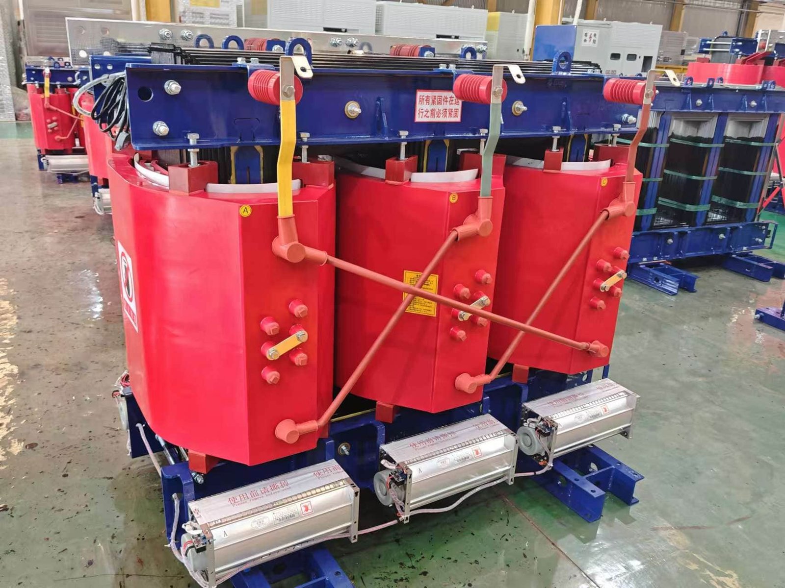
What Are the Key Components of a Power Transformer?

A power transformer may appear externally simple, but internally it is a highly engineered system in which each component plays a precise and irreplaceable role. The reliability, efficiency, safety, and service life of a transformer depend not on a single part, but on how all core components work together under electrical, thermal, and mechanical stress over decades of operation.
The key components of a power transformer include the magnetic core, windings, insulation system, cooling system, tank and enclosure, tap changer, bushings, and monitoring/protection accessories. Each component contributes directly to energy transfer, voltage regulation, heat dissipation, and long-term operational stability.
The performance and lifespan of a power transformer depend on the coordinated function of its core, windings, insulation, and cooling system.True
Transformer efficiency, reliability, and safety are achieved only when all major components are correctly designed and integrated.
Magnetic Core
The magnetic core is the heart of electromagnetic energy transfer:
- Provides a low-reluctance path for magnetic flux
- Ensures strong coupling between windings
- Reduces magnetizing current and core losses
Cores are typically made from laminated silicon steel or amorphous metal to minimize hysteresis and eddy current losses. Core design directly affects efficiency, noise level, and no-load losses.
Primary and Secondary Windings
Windings are the electrical conductors that carry current and define voltage levels:
- Primary winding receives input voltage
- Secondary winding delivers transformed voltage
- Turns ratio determines voltage transformation
Windings are usually made of copper or aluminum and are mechanically reinforced to withstand short-circuit forces and thermal expansion.
Insulation System
The insulation system separates energized parts and prevents electrical breakdown:
- Solid insulation (paper, pressboard, epoxy, resin)
- Liquid insulation (mineral oil, ester fluids) or air/resin in dry-type units
Insulation performance determines voltage class, thermal rating, and service life. Aging of insulation is the primary factor limiting transformer lifespan.
Cooling System
Transformers generate heat due to electrical losses, and effective cooling is essential:
- Oil-immersed cooling using natural or forced circulation
- Dry-type air cooling (natural or forced ventilation)
Cooling systems control temperature rise, prevent thermal degradation, and allow higher loading capability.
Tank and Enclosure
The tank provides mechanical protection and environmental sealing:
- Houses the core, windings, and insulation
- Contains insulating oil in oil-filled transformers
- Provides structural support and grounding
Tank design also influences heat dissipation and corrosion resistance.
Tap Changer
Tap changers regulate output voltage by adjusting winding turns:
- Off-circuit tap changers for infrequent adjustments
- On-load tap changers (OLTC) for voltage regulation under load
Tap changers are critical for maintaining voltage stability in power networks.
Bushings
Bushings allow safe connection of external conductors:
- Provide insulated paths through the tank or enclosure
- Withstand high electrical and mechanical stress
- Maintain insulation coordination
Bushing failures are a common cause of transformer outages, making their quality essential.
Monitoring and Protection Accessories
Modern power transformers include multiple auxiliary components:
- Temperature indicators and sensors
- Oil level and pressure gauges
- Gas relays (Buchholz relay)
- Online monitoring systems
These components detect abnormal conditions early and prevent catastrophic failures.
Mechanical Support Structures
Internal clamps, spacers, and frames:
- Maintain precise winding geometry
- Resist short-circuit forces
- Reduce vibration and noise
Mechanical integrity is essential for both electrical performance and long-term reliability.
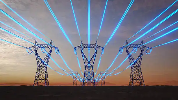
How Does a Power Transformer Change Voltage Levels?
In power systems, electricity must move efficiently over long distances and then be delivered safely at usable voltages. A power transformer makes this possible by changing voltage levels without converting energy into mechanical motion or using electronic switching. Instead, it relies on a stable physical principle that has proven reliable for more than a century.
A power transformer changes voltage levels through electromagnetic induction: an alternating current in the primary winding creates a changing magnetic flux in the core, which induces a voltage in the secondary winding proportional to the ratio of turns between the windings. This process allows voltage to be stepped up or stepped down efficiently and safely.
Voltage change in a power transformer is determined by the turns ratio of its windings.True
According to Faraday’s Law, the induced voltage in each winding is proportional to the number of turns linked by the same changing magnetic flux.
Alternating Current Creates a Changing Magnetic Field
When an AC voltage is applied to the primary winding:
- Alternating current flows through the conductor
- The current continuously changes magnitude and direction
- A time-varying magnetic field is produced
This changing magnetic field is the essential condition for voltage induction. Direct current cannot sustain this process.
Magnetic Flux Is Shared by All Windings
The magnetic field generated by the primary winding is guided by the transformer core:
- The core provides a low-reluctance magnetic path
- Magnetic flux circulates through the core
- The same flux links both primary and secondary windings
Because both windings experience the same magnetic flux, voltage transformation is stable and predictable.
Faraday’s Law Governs Voltage Induction
Faraday’s Law states that a changing magnetic flux induces voltage in a conductor:
- Faster flux change produces higher induced voltage
- More turns result in greater total induced voltage
Each winding develops its own voltage based on how many turns it has around the core.
Turns Ratio Determines Voltage Increase or Decrease
The key mechanism of voltage change is the turns ratio:
- If the secondary has more turns than the primary, voltage is stepped up
- If the secondary has fewer turns, voltage is stepped down
For example:
- A 1:10 turns ratio produces a tenfold voltage increase
- A 10:1 turns ratio reduces voltage to one-tenth
This relationship is precise and does not depend on load conditions.
Power Balance and Current Adjustment
Although voltage changes, power is conserved:
- Increasing voltage reduces current proportionally
- Decreasing voltage increases current proportionally
This automatic current adjustment allows:
- High-voltage, low-current transmission to reduce losses
- Low-voltage, higher-current delivery for safe utilization
The transformer responds instantly to load demand without control mechanisms.
Electrical Isolation Between Circuits
The primary and secondary windings are not electrically connected:
- Energy crosses the insulation barrier magnetically
- Faults and surges are less likely to propagate
- Safety and system protection are enhanced
This galvanic isolation is a major advantage of transformer-based voltage control.
Stable Operation Without Mechanical Motion
Voltage transformation occurs entirely through electromagnetic interaction:
- No moving parts are required
- No friction or mechanical wear exists
- Efficiency remains extremely high
This is why power transformers can operate continuously for decades with minimal maintenance.
What Are the Different Types of Power Transformers?
Power transformers are not one-size-fits-all devices. Different power systems, voltage levels, installation environments, and operational requirements demand different transformer designs. Selecting the wrong type can lead to inefficiency, higher losses, safety risks, and unnecessary lifecycle costs. Understanding the main types of power transformers helps utilities, engineers, and industrial users choose the most suitable solution for reliable long-term operation.
Power transformers are classified based on application, voltage level, cooling method, construction, and function, with each type optimized for specific operating conditions and system requirements.
Different types of power transformers are designed to meet specific voltage, load, and installation requirements.True
Transformer classification reflects differences in function, cooling, insulation, and application rather than a single universal design.
Step-Up and Step-Down Power Transformers
One of the most fundamental classifications is based on voltage transformation direction.
- Step-up transformers increase voltage from the generator level to high transmission voltages, reducing current and minimizing transmission losses.
- Step-down transformers reduce voltage from transmission or sub-transmission levels to distribution or utilization levels suitable for consumers and equipment.
Both types operate on the same electromagnetic principle; only the turns ratio differs.
Transmission and Distribution Power Transformers
Power transformers are also categorized by their position in the power system.
- Transmission power transformers operate at high or extra-high voltages and are designed for maximum efficiency at or near full load.
- Distribution transformers operate at lower voltages and are optimized for high all-day efficiency, as they remain energized continuously under varying load conditions.
The design priorities differ significantly due to their operating profiles.
Oil-Immersed Power Transformers
Oil-immersed transformers are the most widely used type in medium- and high-voltage applications.
Key characteristics:
- Windings and core are submerged in insulating oil
- Oil provides both insulation and cooling
- High overload capability and long service life
They are commonly used in substations, power plants, and transmission networks.
Dry-Type Power Transformers
Dry-type transformers use air or solid insulation instead of liquid oil.
Main advantages:
- No risk of oil leakage or fire spread
- Lower environmental impact
- Suitable for indoor and urban installations
They are widely used in commercial buildings, hospitals, tunnels, renewable energy systems, and industrial facilities where fire safety is critical.
Core-Type and Shell-Type Transformers
Based on magnetic circuit construction, transformers can be classified as:
- Core-type transformers, where windings surround the core limbs
- Shell-type transformers, where the core surrounds the windings
Each design offers different advantages in terms of mechanical strength, cooling efficiency, and short-circuit withstand capability.
Single-Phase and Three-Phase Transformers
Power transformers can be built as:
- Single-phase units, often used in specialized or modular applications
- Three-phase transformers, which are more compact and economical for bulk power transfer
Three-phase transformers dominate modern power systems due to their efficiency and space-saving design.
Auto-Transformers
Auto-transformers use a single winding with taps instead of separate primary and secondary windings.
Advantages include:
- Reduced size and material cost
- Higher efficiency
However, they provide limited electrical isolation and are mainly used where voltage ratios are small, such as interconnecting transmission systems.
Special-Purpose Power Transformers
Certain applications require specialized transformer designs, including:
- Furnace transformers for high-current industrial loads
- Rectifier transformers for DC conversion systems
- Phase-shifting transformers for power flow control
- Renewable energy transformers for wind and solar integration
These designs are tailored to specific electrical and thermal demands.
How Do Power Transformers Maintain Efficiency During Operation?
![]()
In large power systems, even a small efficiency loss in a transformer can translate into significant energy waste, higher operating costs, and increased carbon emissions over decades of service. Because power transformers operate continuously and handle massive energy flows, maintaining high efficiency is not just a design goal but a fundamental requirement for reliable and economical power transmission.
Power transformers maintain efficiency during operation by controlling magnetic behavior, reducing electrical and thermal losses, and operating within carefully designed load and temperature limits throughout their service life.
Power transformers achieve high efficiency primarily by minimizing losses rather than by converting energy more effectively.True
Transformers are passive devices, so efficiency depends on reducing core, copper, and stray losses through design, materials, and operating conditions.
Controlling Core Losses During Continuous Energization
Core losses, also known as no-load losses, occur whenever the transformer is energized, regardless of whether it is supplying load.
Efficiency is maintained by:
- Using high-quality grain-oriented silicon steel or amorphous metal cores
- Designing thin laminated cores to limit eddy currents
- Operating at optimized magnetic flux density
These measures reduce hysteresis and eddy-current losses, which dominate efficiency at light-load conditions.
Reducing Copper and Load-Dependent Losses
Load losses increase with current and become dominant at higher load levels.
Transformers reduce these losses by:
- Selecting low-resistance copper or aluminum conductors
- Increasing conductor cross-sectional area to lower current density
- Using transposed winding conductors to minimize circulating and stray losses
Lower winding resistance directly improves efficiency at medium and high load operation.
Optimized Flux Distribution and Leakage Control
Efficiency is influenced by how magnetic flux flows within the transformer:
- Proper core geometry ensures uniform flux distribution
- Reduced leakage flux minimizes additional heating in structural parts
- Balanced winding layout improves electromagnetic coupling
Good magnetic design reduces stray losses and improves overall efficiency stability.
Thermal Management and Cooling Efficiency
Temperature rise has a direct effect on efficiency:
- Higher temperatures increase winding resistance
- Excess heat accelerates insulation aging and loss growth
Transformers maintain efficiency through:
- Natural or forced oil and air cooling systems
- Radiators, fans, or oil pumps matched to load conditions
- Thermal designs that keep hot-spot temperatures within limits
Effective cooling stabilizes electrical resistance and prolongs efficient operation.
Operating Near the Designed Load Range
Transformers are designed for maximum efficiency near their rated load:
- Light loading increases the relative impact of core losses
- Overloading increases copper losses and thermal stress
Correct transformer sizing ensures that most operating hours occur within the optimal efficiency zone.
High-Integrity Insulation and Assembly
Well-designed insulation systems:
- Prevent partial discharge and dielectric losses
- Maintain consistent electrical clearances
- Preserve strong magnetic coupling between windings
Precision manufacturing and tight mechanical assembly also reduce vibration-related and stray losses.
Long-Term Monitoring and Maintenance
Efficiency is preserved over decades through:
- Regular inspection of cooling systems
- Monitoring load, temperature, and insulation condition
- Early detection of abnormal heating or loss increase
Modern online monitoring systems help operators maintain peak efficiency throughout the transformer’s lifecycle.
Conclusion
Power transformers work based on the principle of electromagnetic induction, where energy is transferred between windings without direct electrical contact. This allows them to efficiently adjust voltage levels, ensuring electricity can be transmitted over long distances with minimal loss and used at safe levels in homes, businesses, and industries. By understanding their core operation, design, and efficiency considerations, we can better appreciate their essential role in modern power systems.
FAQ
Q1: How do power transformers work in simple terms?
Power transformers work by transferring electrical energy from one circuit to another using electromagnetic induction, without any direct electrical connection. When alternating current (AC) flows through the primary winding, it creates a changing magnetic field in the transformer core. This magnetic field induces a voltage in the secondary winding, allowing energy to be delivered at a different voltage level.
The frequency of the power remains unchanged, but the voltage and current levels are transformed according to the winding turns ratio. This principle makes power transformers essential for efficient transmission and distribution of electricity.
Q2: What is the role of electromagnetic induction in a power transformer?
Electromagnetic induction is the fundamental operating principle of all power transformers. According to Faraday’s Law, a changing magnetic flux induces voltage in a conductor. In a power transformer:
AC in the primary winding produces alternating magnetic flux
The flux flows through the magnetic core
The same flux links the secondary winding
A voltage is induced proportional to the number of turns
This process allows power transfer without moving parts, ensuring high efficiency and long service life.
Q3: How do transformer windings determine voltage levels?
Voltage transformation depends on the turns ratio between the primary and secondary windings:
If the secondary has more turns than the primary, voltage is stepped up
If the secondary has fewer turns, voltage is stepped down
Mathematically, the voltage ratio equals the turns ratio. As voltage increases, current decreases proportionally, allowing efficient power transmission over long distances with reduced losses.
Q4: What is the function of the transformer core?
The transformer core provides a low-reluctance path for magnetic flux, ensuring efficient coupling between windings. It is typically made of laminated silicon steel to minimize:
Eddy current losses
Hysteresis losses
Energy dissipation as heat
By guiding the magnetic field effectively, the core improves efficiency and reduces transformer size and losses.
Q5: Why are power transformers used in transmission systems?
Power transformers are critical in transmission systems because they enable:
High-voltage transmission, reducing line losses
Voltage step-down near load centers for safe distribution
Grid stability and voltage control
Efficient energy transfer over long distances
Without power transformers, modern large-scale power grids would be impractical and inefficient.
Q6: What is the difference between power transformers and distribution transformers?
While both operate on the same principle, their applications differ:
Power transformers operate at high voltages and large capacities, mainly in transmission and substation networks. They are optimized for high efficiency at or near full load.
Distribution transformers supply electricity directly to consumers and are optimized for efficiency at varying or lower load levels.
Both types rely on electromagnetic induction and have no moving parts.
Q7: How is efficiency achieved in power transformers?
High efficiency is achieved through:
High-quality core materials
Optimized winding design
Proper insulation systems
Effective cooling methods (oil or air)
Modern power transformers typically achieve efficiencies above 98%, making them among the most efficient electrical machines in use today.
References
IEC 60076 – Power Transformers
https://webstore.iec.ch/publication/602
IEEE C57 Series – Power Transformer Standards
https://standards.ieee.org
Schneider Electric – Transformer Operating Principles
https://www.se.com
Electrical Engineering Portal – Power Transformer Basics
https://electrical-engineering-portal.com
NEMA – Transformer Design and Operation
https://www.nema.org
U.S. Department of Energy – Electricity Transmission Basics
https://www.energy.gov
