A power transformer’s nameplate and technical datasheet contain critical information that defines its electrical characteristics, design standards, and operational limits. Understanding how to interpret these details is essential for engineers, technicians, and operators involved in specification, installation, maintenance, and troubleshooting. This guide explains how to read a transformer's nameplate and datasheet effectively.
What Basic Information Is Found on a Transformer Nameplate?
A transformer nameplate is the identity card of the transformer, containing essential specifications and operating limits defined by the manufacturer. This information is critical for installation, operation, maintenance, troubleshooting, and regulatory compliance. Misinterpreting or overlooking nameplate data can lead to incorrect connections, overload, or operational failure.
The basic information found on a transformer nameplate includes rated power (kVA or MVA), primary and secondary voltage, frequency (Hz), phase and vector group, cooling method, impedance (%), temperature rise, insulation class, serial number, manufacturing standard (e.g., IEC, ANSI), and year of manufacture. This data ensures proper integration with the electrical system.
Nameplate data should always be cross-verified before energization, connection, or relay calibration.
The transformer nameplate only shows the voltage and nothing else.False
A transformer nameplate includes power rating, voltage, impedance, vector group, cooling type, frequency, and several other critical specifications.
Key Nameplate Fields and What They Mean
| Field Name | Description |
|---|---|
| Rated Power (kVA/MVA) | Maximum load transformer can handle continuously |
| Primary Voltage (HV) | Input voltage on high-voltage side |
| Secondary Voltage (LV) | Output voltage on low-voltage side |
| Rated Frequency | Typically 50 Hz or 60 Hz |
| Phase/Vector Group | Phase configuration and winding connection type (e.g., Dyn11) |
| Impedance (%) | Short-circuit impedance affecting voltage regulation and fault current |
| Cooling Method | Type of cooling system used (ONAN, ONAF, OFAF, OFWF) |
| Temperature Rise (°C) | Permissible temperature above ambient (e.g., 55°C) |
| Insulation Class | Thermal class of insulation materials used |
| Serial Number | Unique ID for traceability and maintenance history |
| Year of Manufacture | Useful for aging and asset planning |
| Standard/Code Compliance | Design standard (IEC 60076, ANSI C57, etc.) |
| Tap Changer Range | Voltage adjustment capability (e.g., ±5% in 2.5% steps) |
| Weight (Core/Oil/Total) | Dry weight, oil weight, total transport or operating weight |
Example Transformer Nameplate Layout
| Field | Sample Value |
|---|---|
| Rated Power | 2500 kVA |
| Primary Voltage | 33 kV |
| Secondary Voltage | 0.415 kV |
| Frequency | 50 Hz |
| Vector Group | Dyn11 |
| Cooling Type | ONAN |
| Impedance | 6.25% |
| Temperature Rise | 55°C |
| Tap Range | ±5% in 2.5% steps |
| Serial Number | LNTS2025-11489 |
| Weight (Total) | 3450 kg |
| Manufacture Year | 2025 |
| Standard | IEC 60076 |
Application Relevance of Nameplate Data
| Data Field | Application in System Integration |
|---|---|
| Impedance | Used to calculate fault level and protection relay settings |
| Vector Group | Critical for phasing, paralleling transformers, and earthing |
| Cooling Type | Determines installation requirements (e.g., need for fan circuits) |
| Tap Changer Range | Supports voltage regulation in varying load conditions |
| Serial Number | Essential for spares, service records, warranty claims |
Real-World Use Example
- Scenario: Replacing a failed transformer in a distribution yard
- Action: New unit's vector group found to be Yyn0 instead of original Dyn11
- Result: Phase shift mismatch caused voltage imbalance and tripping
- Lesson: Always match nameplate vector group and impedance before replacement
What Do the Voltage Ratings and Tap Changer Ranges Mean?
Understanding voltage ratings and tap changer ranges is fundamental to operating and integrating oil-immersed transformers in power systems. These parameters define how the transformer connects to the electrical grid, how it maintains voltage levels under variable load, and how it adapts to grid voltage fluctuations or line losses.
Voltage ratings specify the nominal primary (HV) and secondary (LV) voltages a transformer is designed to handle, while the tap changer range allows small percentage adjustments to the HV winding to regulate the output voltage. Tap changers typically provide ±5% to ±15% adjustment in defined steps (e.g., 2.5%) to maintain stable downstream voltage under varying load or supply conditions.
These features ensure optimal transformer performance, grid compatibility, and voltage stability across the network.
Transformer tap changers change the low-voltage side voltage directly.False
Tap changers operate on the high-voltage winding to adjust turns ratio and indirectly regulate the low-voltage output.
1. Voltage Ratings: HV and LV Windings
| Voltage Rating Term | Description |
|---|---|
| Primary Voltage (HV) | The nominal input voltage the transformer receives (e.g., 33 kV) |
| Secondary Voltage (LV) | The nominal output voltage supplied to the load (e.g., 0.4 kV) |
| Rated Voltage | Defined under standard operating conditions at rated frequency |
| Phase Configuration | Specifies single-phase or three-phase system (e.g., 3Ø) |
Example:
- HV = 33,000 V
- LV = 415 V
- Frequency = 50 Hz
- Phase = 3-phase, 4-wire
2. Tap Changer Function and Adjustment Range
| Tap Changer Type | Operation | Application |
|---|---|---|
| Off-Load Tap Changer (OLTC) | Manual adjustment when de-energized | Smaller distribution transformers |
| On-Load Tap Changer (OLTC) | Automatic or remote control while energized | High-voltage grid and industrial systems |
| Tap Range Setting | Function |
|---|---|
| ±5% in 2.5% steps | Allows 3 steps: -5%, -2.5%, 0%, +2.5%, +5% |
| ±10% in 1.25% steps | Allows 9 taps, more precise voltage control |
| Custom ranges | Tailored for voltage-critical or renewable installations |
The tap changer adjusts the number of HV winding turns, slightly altering the turns ratio to regulate the output voltage on the LV side.
Tap Position Voltage Impact Example
| Tap Position | HV Tap Voltage | Resulting LV Output (at constant load) |
|---|---|---|
| -5% | 31,350 V | ↓ Slight LV drop compensated |
| -2.5% | 32,175 V | ↓ Less compensation |
| 0% (Nominal) | 33,000 V | Standard output (415 V) |
| +2.5% | 33,825 V | ↑ Slight LV boost |
| +5% | 34,650 V | ↑ Greater LV boost |
Why Tap Changer Range Matters
| Application Scenario | Importance of Tap Range |
|---|---|
| Voltage Drop at Load End | Tap range compensates for line losses over long distances |
| Grid Fluctuations | Maintains LV stability during HV voltage variation |
| Renewable Integration | Manages output irregularities from solar or wind sources |
| Power Quality Assurance | Ensures equipment receives proper voltage under all conditions |
Real-World Example – 11/0.415 kV Distribution Transformer
- Rated Power: 630 kVA
- Tap Range: ±5% in 2.5% steps (5 tap positions)
- Use Case: Urban feeder with morning/evening load spikes
- Tap Position Adjusted Weekly to Match Peak Voltage
Result: LV side voltage consistently held between 400–420 V, reducing complaints and improving power quality compliance
How Are Current Ratings and Impedance Specified on Oil-Immersed Transformers?
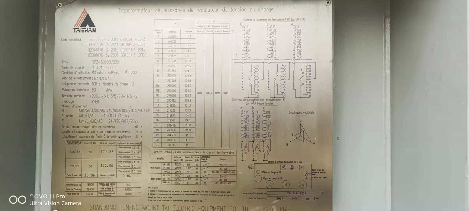
![]()
When designing, installing, or protecting oil-immersed transformers, understanding their current ratings and impedance is essential. These parameters determine how much current the transformer can safely carry, how much voltage drop occurs during load or fault conditions, and how protective relays are configured.
Current ratings on oil-immersed transformers are derived from the rated power (kVA/MVA) and voltage level, and indicate the maximum continuous current the transformer can carry under standard operating conditions. Impedance, expressed as a percentage (%), represents the voltage drop across the transformer under full-load current and also limits the short-circuit current during faults. Both values are clearly stated on the transformer nameplate and are essential for thermal design, voltage regulation, and fault protection.
They are not arbitrary—they ensure safety, coordination, and optimal transformer performance.
Transformer impedance has no impact on short-circuit current.False
Transformer impedance directly determines the maximum short-circuit current by limiting how much fault current can flow through the windings.
1. Rated Current – What It Means and How It’s Calculated
| Parameter | Description |
|---|---|
| Rated Current (HV/LV) | Maximum continuous current per winding at rated load |
| Units | Amperes (A), per winding (e.g., 69.5 A on HV, 3470 A on LV) |
| Derived From | Rated power (S) and voltage (V) using standard formula |
Formula:
For three-phase transformer:
$$I = \frac{S}{\sqrt{3} \times V}$$
Where:
- $I$ = Current in amperes
- $S$ = Apparent power in VA
- $V$ = Voltage in volts (line-to-line)
Example:
- 2500 kVA, 33/0.415 kV transformer
- HV Current = $\frac{2,500,000}{\sqrt{3} \times 33,000} \approx 43.7 A$
- LV Current = $\frac{2,500,000}{\sqrt{3} \times 415} \approx 3477 A$
2. Impedance – Role, Impact, and Specification
| Parameter | Description |
|---|---|
| Impedance (%) | Voltage drop due to transformer internal resistance/reactance |
| Typical Range | 4% to 12% depending on size, cooling, and system requirements |
| Listed on Nameplate | Always specified in %, referred to base MVA rating |
Meaning:
- A 6% impedance means the HV side voltage must drop by 6% to drive full-load current into a short-circuited LV side
- Higher impedance = lower fault current, but greater voltage drop under load
Impedance vs. Short-Circuit Current Calculation
| Impedance (%) | Short-Circuit Current (multiplier of full-load) |
|---|---|
| 4% | 25× full-load current |
| 6% | 16.7× full-load current |
| 8% | 12.5× full-load current |
| 10% | 10× full-load current |
Protective devices must be coordinated with this fault current level using CT ratios and time-current curves.
Nameplate Example: Current and Impedance Specs
| Nameplate Field | Sample Value |
|---|---|
| Rated Power | 2500 kVA |
| HV Voltage | 33 kV |
| LV Voltage | 0.415 kV |
| HV Rated Current | 43.7 A |
| LV Rated Current | 3477 A |
| Impedance (at 75°C) | 6.25% |
| Frequency | 50 Hz |
| Vector Group | Dyn11 |
Application Relevance
| Design/Operation Factor | Role of Current Rating and Impedance |
|---|---|
| Cable/Busbar Sizing | Must match continuous rated current of each winding |
| Relay Protection Settings | Impedance affects fault current calculation |
| Voltage Regulation | Higher impedance increases load-induced voltage drop |
| Transformer Paralleling | Impedances must be matched for load sharing |
| Thermal Aging | Exceeding rated current accelerates insulation breakdown |
Real-World Example – Industrial Load Center
- Transformer: 5 MVA, 11/0.4 kV, 6% impedance
- Load: Motor-heavy, 4200 A LV side
- Issue: Relay tripped during startup surge
- Root Cause: Fault current exceeded breaker interrupting rating
- Resolution: Upgraded breaker and relay to match Isc = FL × (1/Z%) = 83.3 kA
Proper impedance interpretation avoided equipment damage and reconfigured protection scheme
What Cooling Class Codes Appear and What Do They Indicate on Oil-Immersed Transformers?
Cooling is one of the most critical design aspects of oil-immersed transformers. As transformers operate, they generate heat from copper and core losses, which must be dissipated to avoid overheating and insulation failure. The cooling class code—stated on the transformer nameplate—tells you how heat is removed from the transformer’s core and windings, using combinations of natural or forced oil circulation and external cooling media.
Cooling class codes such as ONAN, ONAF, OFAF, and OFWF describe the transformer’s internal and external cooling methods. The first two letters indicate the nature of oil movement (O = oil; N = natural, F = forced), and the last two letters indicate the medium and method of external heat dissipation (A = air, W = water; N = natural, F = forced). These codes define the thermal performance, power rating limits, and physical cooling equipment required.
Each code is standardized under IEC 60076-7 and IEEE C57.12.00.
Cooling class codes only apply to dry-type transformers, not oil-filled ones.False
Cooling class codes are especially important for oil-filled transformers and are used to specify how oil and ambient media dissipate heat.
Cooling Class Code Structure
| Code Position | Meaning |
|---|---|
| 1st Letter | Internal fluid (O = oil) |
| 2nd Letter | Oil movement: N = natural, F = forced by pump |
| 3rd Letter | External cooling fluid: A = air, W = water |
| 4th Letter | Movement of cooling fluid: N = natural, F = forced (fans, pumps) |
Example: ONAF = Oil Natural Air Forced (natural oil flow, fans cool radiators)
Common Cooling Class Codes and Their Use Cases
| Cooling Code | Full Form | Description | Typical Rating Range | Best Suited For |
|---|---|---|---|---|
| ONAN | Oil Natural Air Natural | No pumps or fans; heat radiates through tank/radiators naturally | ≤10–25 MVA | Standard distribution or small substations |
| ONAF | Oil Natural Air Forced | Natural oil, fan-cooled air radiators | 25–60 MVA | Medium-sized grid or industrial transformers |
| OFAF | Oil Forced Air Forced | Oil pumped and air fans used for active cooling | 60–200 MVA+ | Transmission substations, critical loads |
| OFWF | Oil Forced Water Forced | Oil and water both pumped, heat exchangers used | ≥200–1000+ MVA | Power plants, confined indoor sites |
Performance Comparison by Cooling Class
| Parameter | ONAN | ONAF | OFAF | OFWF |
|---|---|---|---|---|
| Heat Removal | Passive | Active (air fans) | Active (oil + air) | Active (oil + water) |
| Complexity | Low | Moderate | High | Very High |
| Cooling Equipment | Radiators | Radiators + fans | Radiators + pumps | Heat exchangers + pumps |
| Overload Capacity | Minimal | 1.3–1.4× rated | 1.6–1.8× rated | Up to 2.0× rated |
| Maintenance Needs | Lowest | Fan checks | Fan + pump checks | Highest |
| Application Environment | Outdoor/open | Urban/utility | Heavy industrial | Indoor, offshore, plant-based |
Typical Dual-Cooling Configurations
| Nameplate Entry Example | Meaning |
|---|---|
| 60/80 MVA ONAN/ONAF | 60 MVA capacity with natural cooling; 80 MVA with fans on |
| 100/133/166 MVA ONAN/ONAF/OFAF | Capacity steps increase with added cooling intensity |
Real-World Application – Power Plant Substation
- Transformer: 315 MVA, 400/220 kV, OFWF cooled
- Reason: Indoor installation, no air exhaust allowed
- System: Dual oil pumps and closed-loop water cooling via heat exchangers
- Control: Temperature sensors auto-adjust oil/water flow
Achieved stable operation during 48 °C ambient heatwaves and 24/7 grid loading—cooling class design ensured zero load derating
What Standards and Test References Are Usually Indicated on Oil-Immersed Transformers?
Every oil-immersed transformer must be manufactured, tested, and certified according to international or national standards. These standards ensure safety, compatibility, durability, and performance under real-world grid conditions. They also define what tests must be performed, what parameters are acceptable, and how compliance is verified.
The standards and test references indicated on oil-immersed transformers typically include international norms such as IEC 60076 series, ANSI/IEEE C57 series, and regional standards like GB (China) or IS (India). They cover rating definitions, temperature rise, insulation levels, losses, efficiency, noise, and short-circuit withstand. Transformers are also labeled with the tests they’ve passed—routine, type, and special—as per these standards.
These specifications offer assurance that the transformer will perform reliably in the intended operating environment.
Transformer standards are optional and can be ignored if performance is verified manually.False
Adherence to transformer standards is mandatory for certification, warranty, utility acceptance, and legal compliance.
1. Common International Transformer Standards
| Standard | Origin | Focus Area |
|---|---|---|
| IEC 60076 Series | International | Core standard for power transformers |
| IEEE/ANSI C57 Series | USA | Design, testing, and performance for distribution & power |
| BS EN 60076 | UK | British adaptation of IEC standards |
| GB/T 6451 | China | National Chinese standard for power transformers |
| IS 2026 Series | India | Indian standard based on IEC for power transformers |
| CSA C88 | Canada | Canadian transformer design and safety |
2. Standards Typically Indicated on Nameplate
| Nameplate Field | Example Entry |
|---|---|
| Applicable Standard | IEC 60076-1: Power Transformers – General |
| Insulation Level | 33 kV BIL 170 kV |
| Temperature Rise Standard | 55 °C Oil / 60 °C Winding per IEC 60076-2 |
| Test Reference | Routine and Type Tests per IEC 60076-3 |
| Sound Level Compliance | <55 dB(A) per IEC 60076-10 |
| Efficiency and Loss Limits | Compliant with IEC 60076-20 |
3. Test Categories as Defined by Standards
| Test Category | Description |
|---|---|
| Routine Tests | Mandatory on every unit: turns ratio, insulation resistance, voltage withstand, impedance |
| Type Tests | On prototype unit: temperature rise, lightning impulse, short-circuit withstand |
| Special Tests | Optional: noise level, partial discharge, harmonic analysis, moisture content |
IEC 60076 Series Breakdown
| IEC Sub-Part | Title and Focus |
|---|---|
| IEC 60076-1 | General requirements and rating definitions |
| IEC 60076-2 | Temperature rise limits and cooling performance |
| IEC 60076-3 | Insulation level and dielectric testing |
| IEC 60076-5 | Short-circuit withstand and mechanical stress testing |
| IEC 60076-10 | Sound level measurement and acoustic limits |
| IEC 60076-20 | Energy performance, efficiency classes, and loss limits |
Real-World Example – 33/11 kV 10 MVA Transformer
- Standard: IEC 60076-1 to -5
- Nameplate Reference: “Complies with IEC 60076 series; routine/type tested”
- Test Results Included: TTR, insulation resistance, BDV, temp rise, impulse test
- Delivered with: Factory Acceptance Test (FAT) report and third-party witness certificate
Outcome: Approved for utility grid connection and long-term warranty validated
Role of Standards in Transformer Procurement
| Procurement Requirement | Associated Standard/Reference |
|---|---|
| Efficiency Specification | EU Eco Design (Tier 1/2), IEC 60076-20, DOE 2016 (USA) |
| Environmental Compliance | IEC 60076-22 for fire behavior, ISO 14001 for environment |
| Grid Connection Approval | Must meet utility’s preferred standards (e.g., IEEE or IEC) |
| Third-Party Testing | Often required to verify standard conformity |
How to Interpret Additional Information like Weight, Dimensions, and Oil Volume on Oil-Immersed Transformers?

Beyond electrical characteristics, a transformer’s mechanical and physical specifications—such as weight, dimensions, and oil volume—are critical for logistics, installation planning, structural support, handling safety, and maintenance procedures. This information appears on the nameplate or in technical data sheets and is essential for crane selection, shipping coordination, foundation design, and oil management.
The weight, dimensions, and oil volume data on a transformer indicate its physical size, lifting requirements, structural support needs, oil handling volume, and space allocation. Total weight includes core, tank, oil, and accessories. Dimensions define the transformer footprint and height, while oil volume guides oil treatment, storage, and fire containment design.
Understanding these values ensures safe, compliant, and efficient installation and operation.
Transformer weight and oil volume are not important as long as voltage ratings are correct.False
Weight, oil volume, and dimensions are vital for installation logistics, foundation sizing, transport safety, and fire/oil containment planning.
1. Weight Parameters Explained
| Weight Type | Meaning |
|---|---|
| Core & Coil Weight | Steel core and copper/aluminum windings only |
| Tank Weight | Bare steel tank without fittings |
| Oil Weight | Mass of insulating oil inside tank (usually in kg or liters × density) |
| Total Operating Weight | Fully assembled transformer ready for service |
| Transport Weight | As-shipped weight (may exclude radiators, conservator, bushings) |
Example:
| Component | Value |
|---|---|
| Core & Coil | 4200 kg |
| Tank | 1500 kg |
| Oil | 1800 kg |
| Accessories | 500 kg |
| Total Weight | 8000 kg |
2. Transformer Dimensions
| Dimension | Description |
|---|---|
| Length (L) | Horizontal distance across tank and fittings |
| Width (W) | Side-to-side footprint (excl. radiators) |
| Height (H) | From base to highest point (e.g., bushings) |
Use Cases:
- Foundation Design
- Transport Envelope Clearance
- Crane Boom Height Estimation
- Enclosure or Substation Layout
Example:
| Dimension | Value |
|---|---|
| Length | 2.6 m |
| Width | 1.8 m |
| Height | 2.4 m |
3. Oil Volume and Implications
| Oil Parameter | Importance |
|---|---|
| Oil Volume (liters) | Volume of insulating/cooling oil inside tank |
| Fire Risk Assessment | Used to size fire suppression and containment systems |
| Oil Handling | Determines dehydration/filtration requirements |
| Spill Containment | Drives bund wall or pit capacity (110% of total oil) |
Oil Density Conversion:
- Mineral oil ≈ 0.88 kg/liter
- Estimation:
Oil Volume (liters) × 0.88 kg/l = Oil Mass (kg)
4. Logistics and Safety Application Table
| Parameter | Installation Impact |
|---|---|
| Total Weight | Crane capacity, road transport permit, base slab strength |
| Height (with bushings) | Clearance under roof, cable duct routing |
| Oil Volume | Bund pit design, fire foam calculation, oil filtration setup |
| Transport Weight | Determines how transformer is shipped (trailers, containers) |
Real-World Scenario – Installation of 20 MVA 66/11 kV Transformer
- Total Weight: 28,600 kg
- Dimensions: 4.5 m × 2.5 m × 3.1 m
- Oil Volume: 7200 liters
- Action: Site team used 40-ton mobile crane and laid reinforced concrete base
- Oil bund pit sized at 8000 liters with sump and oil-water separator
Result: Safe installation with no lifting or oil handling incidents, transformer energized within 48 hours of delivery
Conclusion
Reading a transformer’s nameplate and technical datasheet is key to understanding its design limits, compatibility, and operational parameters. From electrical ratings and tap settings to cooling methods and physical characteristics, each item provides essential data for safe and effective deployment. Mastering this skill ensures correct installation, compliance with design requirements, and confidence in daily operation and long-term maintenance.
FAQ
Q1: What is the purpose of a transformer nameplate and datasheet?
A1: The nameplate and technical datasheet provide essential specifications for identifying, operating, and maintaining a transformer. These include:
Electrical ratings
Cooling methods
Connection configurations
Protection details
They ensure correct installation, load matching, and safe operation according to design standards.
Q2: What key details are found on a transformer nameplate?
A2: Typical nameplate information includes:
Rated Power (kVA/MVA): Maximum load capacity
Primary and Secondary Voltage: Nominal input and output voltages
Frequency (Hz): Usually 50 or 60 Hz
Cooling Class: E.g., ONAN, ONAF, OFAF
Impedance (%): Affects fault current levels and voltage regulation
Vector Group: E.g., Dyn11, indicating winding configuration and phase shift
Serial Number & Manufacturer
Weight and Oil Volume
Temperature Rise Limit and insulation class
Q3: How do you interpret the vector group on a transformer nameplate?
A3: The vector group (e.g., Dyn11) indicates:
Winding configuration: D = Delta, Y = Wye, N = Neutral
Phase shift: '11' means 30° lag between primary and secondary
Understanding vector groups helps with parallel operation, phase alignment, and system compatibility.
Q4: What should you check on the transformer datasheet?
A4: The datasheet provides detailed specs beyond the nameplate, such as:
No-load and load losses
Winding resistance
Insulation level (BIL)
Tap changer range and steps
Cooling surface area and fan specs (if applicable)
Efficiency at various load levels
Drawings for terminals, tank dimensions, and bushing layout
This data supports design integration, load planning, and site preparation.
Q5: Why is understanding the nameplate and datasheet important?
A5: Ensures correct transformer selection and safe operation
Prevents overloading and connection errors
Assists in fault diagnosis and maintenance planning
Facilitates regulatory and warranty compliance
Accurate interpretation is vital for engineers, installers, and operators alike.
References
"How to Read a Transformer Nameplate" – https://www.electrical4u.com/transformer-nameplate-details
"IEEE Standard C57.12.00: Transformer Nameplate Requirements" – https://ieeexplore.ieee.org/document/8889732
"NREL: Technical Documentation for Power Equipment" – https://www.nrel.gov/docs/transformer-datasheet-guide.pdf
"ScienceDirect: Reading Transformer Electrical Data" – https://www.sciencedirect.com/transformer-data-interpretation
"Doble: Transformer Specification and Nameplate Analysis" – https://www.doble.com/transformer-nameplate-tutorial