Transformers play a critical role in the transmission and distribution of electrical power by changing voltage levels efficiently. Whether stepping up voltage for long-distance transmission or stepping it down for safe usage in homes and industries, the working principle remains rooted in electromagnetic induction. This article outlines how transformers perform this essential function.
What Principle Allows Transformers to Change Voltage?
In electrical systems, stepping voltage up or down efficiently and safely is critical for power distribution—from generation stations to homes and industries. But how can voltage be increased or decreased without mechanical parts or active electronics? The answer lies in the fundamental principle of electromagnetic induction. Transformers use this core principle to alter AC voltage levels while conserving power (neglecting losses). Understanding how this principle works is key to understanding the role of transformers in modern power systems.
The principle that allows transformers to change voltage is electromagnetic induction. When alternating current flows through the primary coil of a transformer, it creates a changing magnetic field in the core. This magnetic field induces a voltage in the secondary coil. The voltage ratio between the primary and secondary depends on the ratio of the number of turns in each coil—allowing the transformer to step voltage up or down without changing frequency.
This simple, passive process is the foundation of power transmission and distribution.
Transformers use the principle of electromagnetic induction to change voltage.True
Changing current in the primary coil produces a varying magnetic field, which induces voltage in the secondary coil.
Transformers work with both AC and DC voltages equally well.False
Transformers only work with alternating current (AC), because a changing magnetic field is required to induce voltage.
The voltage change in a transformer depends on the ratio of coil turns.True
The turns ratio directly determines whether the voltage is stepped up or stepped down.
1. Basic Structure of a Transformer and Its Function
| Component | Function |
|---|---|
| Primary Winding | Connected to input AC source; generates magnetic field |
| Secondary Winding | Delivers transformed voltage to the load |
| Magnetic Core | Guides magnetic flux between windings |
| Insulation & Tank | Prevents arcing and contains cooling oil (in large units) |
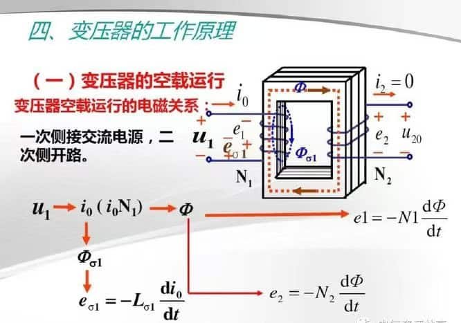
Working Principle:
- AC current enters the primary winding.
- Alternating current produces an alternating magnetic field in the core.
- This changing magnetic field induces a voltage in the secondary winding.
- The induced voltage is proportional to the turns ratio between coils.
2. The Mathematical Principle Behind Voltage Change
Fundamental Equation of a Transformer:
$$
frac{V_s}{V_p} = \frac{N_s}{N_p}
$$
Where:
- $V_s$: Secondary voltage
- $V_p$: Primary voltage
- $N_s$: Number of turns in the secondary coil
- $N_p$: Number of turns in the primary coil
Similarly for Current:
$$
frac{I_s}{I_p} = \frac{N_p}{N_s}
$$
This means:
- Step-up Transformer: $N_s > N_p$ → Voltage increases, current decreases
- Step-down Transformer: $N_s < N_p$ → Voltage decreases, current increases
3. Why Transformers Only Work with AC
| Parameter | Alternating Current (AC) | Direct Current (DC) |
|---|---|---|
| Magnetic Field | Continuously changing | Static (unchanging) |
| Induced EMF | Present due to changing flux | No EMF induced after initial connection |
| Transformer Operation | Functional | Non-functional |
Transformers require changing magnetic fields to induce voltage. Since DC doesn’t change direction or magnitude, it cannot sustain induction in the secondary winding.
4. Types of Transformers Based on Voltage Conversion
| Transformer Type | Function | Example Use |
|---|---|---|
| Step-Up | Increases voltage | From generator (11 kV) to grid (220 kV) |
| Step-Down | Decreases voltage | From grid (33 kV) to local supply (415 V) |
| Isolation | 1:1 ratio, for safety | Industrial control panels |
| Autotransformer | Shared winding | Voltage regulation, reduced size |
5. Practical Example: Voltage Step-Down Calculation
Given:
- Primary voltage $V_p = 11,000 \, \text{V}$
- Turns ratio: $N_p = 2200$, $N_s = 200$
Find $V_s$:
$$
frac{V_s}{11000} = \frac{200}{2200}
Rightarrow V_s = 1000 \, \text{V}
$$
So, the transformer steps 11 kV down to 1 kV.
6. Efficiency Consideration
Transformers are highly efficient due to:
- No moving parts
- Minimal energy loss (95–99%)
- Efficient magnetic core materials (CRGO, amorphous)
Losses still occur, mainly as:
- Core Loss (Iron Loss): Hysteresis + eddy currents
- Copper Loss: $I^2R$ in windings
- Stray Losses: Leakage flux heating nearby metal parts
7. Visual Overview: Transformer Voltage Transformation Process
| Step | Description | Result |
|---|---|---|
| 1 | Apply AC to primary | Current flows |
| 2 | Magnetic field builds in core | Alternating flux |
| 3 | Flux cuts secondary winding | Voltage induced |
| 4 | Secondary voltage depends on turns ratio | Voltage stepped up or down |
What’s the Role of Primary and Secondary Windings?

Every transformer, whether large-scale or compact, relies on two key components to perform its function: the primary and secondary windings. These coils of conductive wire—often made of copper or aluminum—are wound around a shared magnetic core and are fundamental to the transformer’s ability to transfer energy between circuits at different voltage levels. Their configuration determines not only how the voltage is changed but also how safely and efficiently the transformer operates. Understanding the roles of these windings is essential for engineers, technicians, and energy professionals involved in power systems.
The primary winding of a transformer is the coil connected to the input voltage source, where alternating current (AC) flows and creates a changing magnetic field. The secondary winding is the coil where the output voltage is induced by this magnetic field. The number of turns in each winding determines whether the transformer increases (step-up) or decreases (step-down) the voltage. Together, they facilitate energy transfer through electromagnetic induction without a direct electrical connection.
This configuration enables safe, efficient voltage transformation for all levels of power transmission and usage.
The primary winding is connected to the AC source and creates the magnetic field in the core.True
The alternating current in the primary winding generates a magnetic flux that links to the secondary winding.
The secondary winding is responsible for generating a constant DC output.False
Transformers operate only with alternating current; the secondary winding delivers AC voltage based on induction.
Voltage transformation in a transformer depends on the ratio of turns between the primary and secondary windings.True
More turns in the secondary coil than the primary step up voltage, and vice versa.
1. Function of Primary and Secondary Windings in Voltage Transformation
| Winding | Role | Key Function |
|---|---|---|
| Primary | Input side | Receives AC voltage and establishes alternating magnetic flux |
| Secondary | Output side | Converts magnetic flux back into AC voltage for the load |
The two windings do not share electrical continuity, but they interact magnetically through the transformer's core.
2. Electromagnetic Induction in Windings
Process Overview:
- AC voltage applied to primary winding → AC current flows.
- Current produces alternating magnetic flux in the transformer core.
- This flux links with the secondary winding through the core.
- Induced voltage in the secondary winding is proportional to the turns ratio.
Voltage Equation:
$$
frac{V_s}{V_p} = \frac{N_s}{N_p}
$$
Where:
- $V_p$, $V_s$: Voltages on primary and secondary
- $N_p$, $N_s$: Number of turns in each winding
3. Winding Configuration and Transformer Type
| Transformer Type | $N_s > N_p$ | Voltage Effect |
|---|---|---|
| Step-Up | Yes | Output voltage is higher than input |
| Step-Down | No | Output voltage is lower than input |
| Isolation Transformer | $N_s = N_p$ | No voltage change; for safety and signal isolation |
Example:
- $N_p = 100$, $N_s = 400$ → 1:4 turns ratio → 4× voltage increase (step-up)
4. Current and Power Relationship in Windings
While transformers change voltage, they also inversely affect current to maintain the same power (neglecting losses).
Current Relationship:
$$
frac{I_s}{I_p} = \frac{N_p}{N_s}
$$
This means:
- Higher voltage on the secondary → Lower current
- Lower voltage on the secondary → Higher current
Power Conservation:
$$
P{primary} \approx P{secondary} \quad (\text{ignoring losses})
$$
$$
V_p \times I_p \approx V_s \times I_s
$$
5. Construction Considerations for Windings
| Aspect | Design Concern |
|---|---|
| Material | High-conductivity copper or aluminum |
| Turns per coil | Dictates voltage ratio |
| Insulation | Must withstand operational voltages and temperature |
| Cooling | Windings generate heat; must be cooled by oil or air |
| Mechanical strength | Windings must withstand fault currents and vibration |
6. Winding Arrangement Variants
| Type | Description | Use Case |
|---|---|---|
| Concentric Winding | Cylindrical primary and secondary arranged concentrically | Power transformers |
| Sandwich/Interleaved | Layers of windings alternate | Reduces leakage inductance |
| Helical Winding | Spiral winding for high current | Distribution transformers |
| Disc Winding | Flat disc layers for high voltage | Substation class units |
7. Diagnosing Winding Issues
| Diagnostic Tool | Fault Detected |
|---|---|
| Winding Resistance Test | Poor joints, damage |
| SFRA | Mechanical displacement |
| Insulation Resistance (IR) | Moisture, aging |
| Turns Ratio (TTR) | Turn-to-turn short |
A change in resistance, ratio, or frequency response is a warning sign of winding deformation, thermal damage, or connection failure.
8. Real-World Application Example
Transformer: 132/33 kV, 50 MVA Step-Down
- Primary Winding: 132,000 V, 500 turns
- Secondary Winding: 33,000 V, 125 turns
- Turns Ratio: 4:1
- Result: Voltage stepped down to distribution level
- Secondary Current: Higher to maintain power output
What Is the Difference Between Step-up and Step-down Transformers?
Efficient electrical power transmission and usage depend on managing voltage levels precisely—high voltage for long-distance transmission to reduce losses, and low voltage for end-user safety and equipment compatibility. This is where step-up and step-down transformers come into play. Although both types rely on the same core electromagnetic principle, they are configured differently to perform opposite voltage conversion functions. Choosing the wrong type for an application can result in inefficiency, safety risks, or equipment damage.
A step-up transformer increases voltage from a lower primary level to a higher secondary level, while a step-down transformer decreases voltage from a higher primary level to a lower secondary level. The difference lies in the turns ratio of their windings: step-up transformers have more turns on the secondary winding, whereas step-down transformers have more turns on the primary winding. Both types operate on the principle of electromagnetic induction and are used at different stages of power transmission and distribution.
Understanding this distinction is essential for correct transformer selection in utility, industrial, and renewable energy systems.
A step-up transformer has more turns on the secondary winding than the primary.True
More turns on the secondary side induce a higher voltage compared to the input.
Step-down transformers are used at the generation side to transmit power over long distances.False
Step-down transformers are typically used at the distribution end to reduce voltage for safe utilization.
Both step-up and step-down transformers rely on the same operating principle.True
They both use electromagnetic induction and differ only in winding configuration.
1. Basic Principle Behind Both Transformers
Both step-up and step-down transformers use Faraday’s law of electromagnetic induction:
$$
frac{V_s}{V_p} = \frac{N_s}{N_p}
$$
- $V_s$: Secondary voltage
- $V_p$: Primary voltage
- $N_s$: Number of turns on the secondary winding
- $N_p$: Number of turns on the primary winding
This equation governs how voltage changes depending on the winding ratio.
2. Step-up vs Step-down Transformer: A Technical Comparison
| Parameter | Step-up Transformer | Step-down Transformer |
|---|---|---|
| Primary Voltage | Low | High |
| Secondary Voltage | High | Low |
| Winding Configuration | $N_s > N_p$ | $N_s < N_p$ |
| Main Function | Boost voltage for transmission | Reduce voltage for safe use |
| Typical Location | Power generation stations | Distribution substations, consumers |
| Example Rating | 11kV/220kV | 220kV/33kV, 33kV/415V |
| Application | Grid transmission, renewable energy | Industrial and residential supply |
| Current Output | Lower than input (for same power) | Higher than input (for same power) |
3. Working Examples
Step-up Transformer Example
- Primary: 11,000 V, 500 turns
- Secondary: 220,000 V, 10,000 turns
- Used at: Power plant generator output
- Purpose: Boost voltage to minimize line losses during transmission
Step-down Transformer Example
- Primary: 33,000 V, 3,300 turns
- Secondary: 415 V, 41.5 turns
- Used at: Commercial building substation
- Purpose: Reduce voltage for safe equipment use
4. Efficiency and Construction Aspects
| Aspect | Step-up | Step-down |
|---|---|---|
| Core Material | CRGO steel or amorphous | CRGO steel or amorphous |
| Conductor Size | Smaller primary, thicker secondary | Thicker primary, smaller secondary |
| Cooling Requirement | High (due to high voltage) | Moderate |
| Insulation Rating | Higher for secondary | Higher for primary |
Both types can achieve >98% efficiency with proper design and maintenance.
5. Application Sectors by Transformer Type
| Sector | Step-up Use | Step-down Use |
|---|---|---|
| Utility/Grid | Power station output to transmission line | Substations, pole-mounted distribution |
| Renewables | Solar/wind inverter to grid | Load-side in microgrids |
| Industrial | Internal step-up for special equipment | Motors, HVAC, automation |
| Railway | Boost traction supply voltage | Train onboard systems |
| Data Centers | Uplift DC-AC supply in HVDC routes | Voltage conversion to server racks |
6. Real-world Case Study
Wind Power Farm — 500 MW capacity
Step-up transformers: 690 V (turbine) → 33 kV → 220 kV grid
- Increases voltage for export to main transmission grid
Step-down transformers: 220 kV → 33 kV at receiving substations
- Reduces voltage for regional distribution and load connection
This illustrates how both transformer types function within a single power network.
7. Visual Summary Chart
| Feature | Step-Up Transformer | Step-Down Transformer |
|---|---|---|
| Voltage Transformation | ↑ Voltage | ↓ Voltage |
| Turns Ratio | Secondary > Primary | Primary > Secondary |
| Used At | Generation side | Load/distribution side |
| Example Voltage | 11kV → 220kV | 220kV → 415V |
| Output Current | ↓ | ↑ |
8. Common Misconceptions Clarified
| Misconception | Reality |
|---|---|
| Step-up and step-down transformers are completely different machines | False — They are structurally similar; configuration defines their role |
| You can’t reverse a transformer’s function | False — If loads permit, reversing connections reverses function (with correct insulation ratings) |
| Only utilities use step-up transformers | False — Renewable farms and even high-speed trains use them too |
How Does the Turns Ratio Affect Output Voltage?
In any transformer application—whether it’s in a power grid, an industrial facility, or a renewable energy system—the ability to precisely increase or decrease voltage levels is essential. This vital function is controlled not by active electronics, but by a simple passive design factor: the turns ratio. It is the relationship between the number of wire windings on the primary and secondary coils of a transformer, and it determines how much the input voltage will change. Misunderstanding or misapplying this ratio can result in overvoltage, undervoltage, or even equipment failure.
The turns ratio of a transformer is the ratio of the number of windings (turns) on the primary coil to those on the secondary coil, and it directly determines the output voltage. If the secondary coil has more turns than the primary (turns ratio < 1), the voltage is stepped up. If the secondary has fewer turns (turns ratio > 1), the voltage is stepped down. The formula $V_s/V_p = N_s/N_p$ governs this relationship, where $V$ is voltage and $N$ is the number of turns.
Proper calculation of the turns ratio ensures that the transformer delivers the correct voltage level for downstream equipment or grid integration.
The turns ratio determines whether the transformer steps voltage up or down.True
A higher secondary turns count steps up voltage; a lower one steps it down.
If the primary and secondary have the same number of turns, the output voltage will be zero.False
Equal turns result in the same voltage, not zero—such a transformer is known as an isolation transformer.
Voltage and turns ratio are directly proportional in a transformer.True
According to the transformer equation, the ratio of voltages equals the ratio of turns.
1. Understanding the Turns Ratio: The Mathematical Foundation
The transformer voltage equation is:
$$
frac{V_s}{V_p} = \frac{N_s}{N_p}
$$
Where:
- $V_p$: Primary voltage (input)
- $V_s$: Secondary voltage (output)
- $N_p$: Number of primary turns
- $N_s$: Number of secondary turns
Example Calculations:
| $V_p$ | $N_p$ | $N_s$ | Result $V_s$ |
|---|---|---|---|
| 11,000 V | 2200 | 4400 | 22,000 V (Step-up) |
| 33,000 V | 3300 | 660 | 6,600 V (Step-down) |
| 415 V | 100 | 100 | 415 V (Isolation) |
The ratio $N_s/N_p$ is what defines the behavior of the transformer.
2. Types of Turns Ratios and Voltage Effects
| Turns Ratio (N_s\:N_p) | Transformer Type | Voltage Change |
|---|---|---|
| 2:1 | Step-up | Doubles voltage |
| 1:2 | Step-down | Halves voltage |
| 1:1 | Isolation | No change, just galvanic separation |
| 5:1 | Strong step-up | 5× voltage |
| 1:5 | Strong step-down | 1/5 of input voltage |
Voltage Polarity:
The direction of winding (dot convention) determines the phase orientation. Reversing the winding direction reverses voltage polarity.
3. Turns Ratio and Current Behavior
While voltage increases or decreases based on the turns ratio, current behaves inversely:
$$
frac{I_s}{I_p} = \frac{N_p}{N_s}
$$
This ensures power conservation, neglecting losses:
$$
V_p \cdot I_p = V_s \cdot I_s
$$
| Step | Voltage | Current |
|---|---|---|
| Step-up | ↑ | ↓ |
| Step-down | ↓ | ↑ |
4. Real-World Applications of Turns Ratio Control
| Application | Input Voltage | Output Voltage | Turns Ratio |
|---|---|---|---|
| Transmission Boost (Power Plant) | 11 kV | 220 kV | 1:20 |
| Distribution Transformer | 33 kV | 415 V | 80:1 |
| Solar Inverter Transformer | 400 V | 11 kV | 1:27.5 |
| Isolation for UPS | 415 V | 415 V | 1:1 |
| Industrial Furnace Step-down | 6.6 kV | 480 V | 13.75:1 |
5. Diagram: Turns Ratio and Output Voltage Behavior
| Transformer | Primary Turns | Secondary Turns | Turns Ratio | Behavior |
|---|---|---|---|---|
| A | 100 | 200 | 1:2 | Step-up (×2) |
| B | 300 | 100 | 3:1 | Step-down (÷3) |
| C | 100 | 100 | 1:1 | Isolation (same voltage) |
This simple table shows how voltage transforms with coil turn design.
6. Winding Design Considerations
- Higher voltage requires more turns to prevent dielectric breakdown.
- Larger wire cross-sections are used in lower-voltage (high-current) windings.
- The physical layout—helical, disc, layer—affects leakage inductance and efficiency.
- Insulation grade must match the voltage ratio’s stress points.
7. What Happens If the Turns Ratio Is Incorrect?
| Scenario | Effect |
|---|---|
| Too low a secondary turn count | Output voltage too low; equipment underperforms |
| Too high a secondary turn count | Output voltage too high; overvoltage damage risk |
| Wrong phase winding | Phase inversion; destructive harmonics possible |
| Unequal turn spacing | Magnetic imbalance; noise, heat, and flux leakage |
A mismatched turns ratio can ruin both the transformer and the load it supplies.
8. Monitoring Output vs. Turns Ratio
Factory Acceptance Test (FAT) includes:
- Turns Ratio Test (TTR)
- Polarity and Phase Shift Verification
- Voltage Regulation Check at Full Load
Deviations from expected turns ratio may indicate:
- Shorted turns
- Poor tap changer contact
- Mechanical winding deformation
Conclusion
Transformers step voltage up or down by using electromagnetic induction between two windings—primary and secondary—wrapped around a magnetic core. The ratio of turns in these coils directly determines whether voltage increases or decreases. This simple yet powerful mechanism ensures safe and efficient transmission of electricity from generation plants to end users. Understanding this process is fundamental to grasping how modern power systems function.
FAQ
Q1: How does a transformer increase or decrease voltage?
A1: A transformer steps voltage up or down using electromagnetic induction between two or more windings:
Primary winding: Connected to the input voltage source
Secondary winding: Delivers the transformed output voltage
The voltage change depends on the turns ratio between the primary and secondary coils.
Step-up transformer: Secondary has more turns → voltage increases
Step-down transformer: Secondary has fewer turns → voltage decreases
The core transfers the magnetic flux efficiently between windings.
Q2: What is the role of the turns ratio in voltage transformation?
A2: The turns ratio determines the voltage conversion as per the formula:
Vs/Vp = Ns/Np
Where:
Vs = Secondary voltage
Vp = Primary voltage
Ns = Secondary winding turns
Np = Primary winding turns
Example: If Ns is twice Np, the output voltage is twice the input → step-up. If Ns is half of Np, it’s a step-down transformer.
Q3: Does a transformer work with DC voltage?
A3: No. Transformers only work with alternating current (AC) because:
AC creates a changing magnetic field, essential for electromagnetic induction
DC provides a steady field, which doesn’t induce current in the secondary winding
This is why transformers are primarily used in AC power systems.
Q4: What are common applications of step-up and step-down transformers?
A4: Step-up transformers:
Used in power plants to raise generator voltage (e.g., 11kV → 400kV) for long-distance transmission
Step-down transformers:
Found in distribution substations to reduce voltage (e.g., 33kV → 400V) for consumer use
Other examples: adapters, chargers, and industrial equipment all use transformers for voltage conversion.
Q5: How does the transformer maintain constant power?
A5: In ideal conditions (neglecting losses), transformers follow the law of conservation of power:
Input Power = Output Power
Vp × Ip = Vs × Is
If voltage increases, current decreases proportionally, and vice versa. This allows for efficient high-voltage, low-current transmission to reduce losses over distance.
References
Electrical4U: How Transformers Work
https://www.electrical4u.com/working-principle-of-transformer/
IEEE C57 Standards for Voltage Transformers
https://standards.ieee.org/ieee/c57/
Doble: Understanding Transformer Operation
https://www.doble.com/resources/transformer-basics/
NREL: Power System Transformer Behavior
https://www.nrel.gov/docs/fy21osti/transformer-theory.pdf
ScienceDirect: Transformer Electromagnetic Induction Principles
https://www.sciencedirect.com/science/article/pii/S1364032119310512