When electrical energy needs to move between circuits operating at different voltage levels, direct electrical connection is often impractical or unsafe. A transformer provides an efficient way to transfer energy while maintaining electrical isolation between the primary and secondary circuits. Without understanding this process, buyers may find it difficult to evaluate transformer efficiency, winding design, core materials, voltage ratios, and operating reliability. Understanding how a transformer transfers electrical energy is therefore essential for selecting the right transformer for a power system.
A transformer transfers electrical energy through electromagnetic induction. When alternating current flows through the primary winding, it creates a changing magnetic flux in the transformer core. This changing magnetic flux links with the secondary winding and induces an electromotive force, allowing electrical energy to be transferred from the primary circuit to the secondary circuit without a direct conductive connection. The turns ratio determines the voltage transformation, while the transformer design influences current capacity, efficiency, losses, and reliability.
The basic energy-transfer principle is simple, but practical transformer performance depends on the interaction of the magnetic core, windings, insulation system, and cooling arrangement. The following outline explains the process step by step and highlights the key factors buyers should consider when evaluating transformer designs.
Below is an original, citation-free article following the established format, with the explanation centered on electromagnetic induction, magnetic flux, the core, and primary/secondary windings.
How Does a Transformer Transfer Electrical Energy Through Electromagnetic Induction?
Many people understand that a transformer can change voltage, but the more important engineering question is how electrical energy can move from one circuit to another without a direct conductive connection between the primary and secondary windings. If this mechanism is misunderstood, it becomes easy to confuse voltage transformation with energy generation or assume that electrons physically travel through the magnetic core from one winding to the other. In reality, a transformer transfers energy through a changing magnetic field established by the alternating current in the primary winding. The magnetic core provides a low-reluctance path that couples this changing magnetic flux to the secondary winding, where electromagnetic induction produces an induced voltage. Understanding this process is essential for selecting, designing, manufacturing, testing, and operating reliable power transformers.
A transformer transfers electrical energy through electromagnetic induction by converting electrical energy in the primary winding into a time-varying magnetic field in the core, coupling that changing magnetic flux to the secondary winding, and converting the changing magnetic field back into electrical energy in the secondary circuit. When alternating voltage is applied to the primary winding, alternating magnetic flux is established in the core; this changing flux induces voltage in the secondary winding according to Faraday's law. The turns ratio determines the approximate voltage ratio, while the connected load determines the secondary current and the amount of power transferred.
This energy-transfer process is the foundation of step-up transformers, step-down transformers, isolation transformers, distribution transformers, and many industrial power transformers. Although the principle is elegant, practical transformer performance depends on core material, winding arrangement, magnetic flux density, insulation, leakage reactance, resistance, cooling, and manufacturing precision. The following sections explain what happens inside a transformer from the moment the primary winding receives electrical energy to the moment useful power reaches the secondary load.

Electrical energy passes directly through the transformer magnetic core from the primary winding to the secondary winding.False
The magnetic core provides a low-reluctance path for changing magnetic flux and couples the windings magnetically, but it is not a conductive path through which the primary circuit's electrical current directly flows into the secondary circuit.
What Is the Basic Principle Behind Transformer Energy Transfer?
The operating principle of a transformer is electromagnetic induction. Unlike a motor, which converts electrical energy into mechanical energy, or a generator, which converts mechanical energy into electrical energy, a transformer transfers electrical energy between electrical circuits through a changing magnetic field.
Consider a conventional transformer containing a laminated magnetic core, a primary winding, and a secondary winding. The primary winding is connected to an alternating-voltage source. When the source applies voltage to the primary, an alternating current develops in the winding. This current establishes a magnetic field around the conductors. Because the winding surrounds part of the magnetic core, much of the magnetic flux is guided through the core.
The important feature is that the magnetic flux is continuously changing. A stationary magnetic field does not continuously induce voltage in a stationary secondary winding. Transformer action depends on variation of magnetic flux with time. As the alternating primary current changes direction and magnitude, the magnetic flux in the core also changes. That changing flux links the secondary winding and induces an electromotive force, commonly called induced voltage.
The secondary winding therefore receives electrical energy without being electrically connected to the primary winding. When a load is connected to the secondary, the induced voltage drives secondary current through that load. The transformer has completed the energy-transfer chain:
Electrical energy → primary magnetic excitation → changing core flux → induced secondary voltage → secondary electrical energy → load
This distinction is extremely important. The magnetic core is an energy-transfer medium, not a wire connecting the two circuits. The primary and secondary circuits remain electrically isolated in an isolation transformer, even though they are strongly coupled magnetically.
For a power transformer manufacturer, this principle determines many aspects of construction. The core must provide an efficient magnetic path, the windings must be arranged to obtain the required turns ratio and coupling, insulation must withstand the specified electrical stresses, and the complete structure must control losses and temperature. A transformer is therefore much more than two coils placed around a piece of steel. Its performance depends on how effectively the entire electromagnetic system is designed.
How Does the Primary Winding Create Magnetic Flux?
When an AC voltage is applied to the primary winding, current flows through the winding. The current creates magnetomotive force, which establishes magnetic flux in the transformer core. The magnetic core is manufactured from electrical steel or another suitable magnetic material specifically selected to support efficient alternating magnetization.
The core provides a low-reluctance path for magnetic flux. This is important because air has much higher magnetic reluctance than ferromagnetic core materials. By concentrating the magnetic flux inside the core, the transformer allows a large portion of the flux generated by the primary winding to link the secondary winding.
The alternating nature of the excitation is essential. During one portion of the AC cycle, the magnetic flux moves in one direction through the core; during the next portion, it reverses. The resulting time-varying magnetic flux is what creates transformer action.
A simplified energy path can be represented as:
AC source
   │
   ▼
Primary winding
   │
   ▼
Magnetizing current
   │
   ▼
Alternating magnetic flux
   │
   ▼
Magnetic core
   │
   ▼
Flux linkage with secondary winding
   │
   ▼
Induced secondary voltage
   │
   ▼
Secondary current
   │
   ▼
Electrical load
In an ideal transformer, the magnetic coupling would be perfect and losses would be zero. Real transformers are different. Some magnetic flux does not link both windings, producing leakage reactance. Copper resistance causes winding losses. The magnetic core produces hysteresis and eddy-current losses. Additional stray losses can occur in structural components and nearby conductive materials.
These losses explain why a practical transformer requires careful engineering. The transformer manufacturer must optimize core dimensions, winding conductor size, magnetic flux density, insulation structure, cooling system, and mechanical construction so that the desired power can be transferred efficiently and reliably.
What Is Magnetic Flux Linkage?
Magnetic flux describes the amount of magnetic field passing through a defined area. In a transformer, the critical issue is not simply how much magnetic flux exists but how much of that flux links the windings.
If the primary and secondary windings are strongly coupled, most of the useful core flux links both windings. This produces efficient electromagnetic energy transfer. If coupling is poor, more flux becomes leakage flux, reducing voltage regulation and increasing reactive effects.
The transformer core therefore plays a crucial role. A well-designed laminated core provides a controlled magnetic path while reducing unwanted electrical losses caused by eddy currents. Core geometry also influences the length of the magnetic path, joint losses, mechanical construction, and winding arrangement.
The winding arrangement is equally important. Manufacturers may position high-voltage and low-voltage windings concentrically, sandwich them in particular arrangements, or use other winding structures depending on transformer design. The objective is to achieve the required electrical insulation, mechanical strength, leakage impedance, thermal performance, and magnetic coupling.
For buyers, this means that a transformer should not be evaluated only from its nominal voltage and kVA/MVA rating. The internal electromagnetic construction affects efficiency, voltage regulation, short-circuit performance, temperature rise, sound level, and service life.
How Does Faraday's Law Explain Transformer Action?
Faraday's law provides the fundamental mathematical explanation for induced transformer voltage. In practical terms, the magnitude of induced voltage is proportional to the number of turns and the rate at which magnetic flux changes.
For a sinusoidally excited transformer, the familiar RMS relationship can be expressed approximately as:
E ≈ 4.44 f N Φmax
where:
- E = induced RMS voltage
- f = operating frequency
- N = number of winding turns
- Φmax = maximum magnetic flux
This relationship immediately explains several important transformer-design decisions.
If frequency remains constant and the maximum core flux is controlled, increasing the number of turns increases induced voltage. This is why the ratio of primary and secondary turns determines the approximate voltage transformation ratio.
For example, suppose a transformer has 1,000 primary turns and 100 secondary turns. The secondary has one-tenth as many turns as the primary, so the ideal voltage ratio is approximately 1:10. A primary voltage of 10 kV would correspond to approximately 1 kV on the secondary side under idealized conditions.
Conversely, if the secondary has more turns than the primary, the transformer can provide step-up voltage transformation.
The frequency term is also important. A transformer designed for one operating frequency cannot necessarily be operated at a substantially lower frequency without considering magnetic flux density. For a given applied voltage and number of turns, lower frequency can require greater magnetic flux, potentially driving the core toward saturation.
This is why transformer nameplates specify operating frequency and why buyers should never treat frequency as an optional specification.
How Does the Turns Ratio Transfer Energy?
The turns ratio controls voltage transformation, but it does not mean that a step-up transformer creates additional power. In an ideal transformer, input power and output power are approximately equal:
P₁ ≈ P₂
Since electrical power is related to voltage and current, increasing voltage generally corresponds to decreasing current for approximately the same transferred power, while decreasing voltage generally corresponds to increasing current.
The ideal relationships are:
| Transformer Characteristic | Relationship |
|---|---|
| More secondary turns than primary | Step-up voltage |
| Fewer secondary turns than primary | Step-down voltage |
| Equal primary and secondary turns | Approximately 1:1 voltage |
| Higher secondary voltage | Correspondingly lower secondary current for similar power |
| Lower secondary voltage | Correspondingly higher secondary current for similar power |
| Ideal input power | Approximately equal to output power |
| Real input power | Greater than useful output power because of losses |
Consider an ideal 100 kVA transformer. On the high-voltage side, the current may be relatively low. On the low-voltage side, the current can be substantially higher. This is one reason low-voltage windings often require large conductors or specialized winding arrangements.
The transformer does not violate conservation of energy. It changes the voltage-current combination while transferring approximately the same amount of power, less losses.
How Does the Secondary Winding Receive Energy?
Once the alternating magnetic flux established by the primary winding links the secondary winding, the changing flux induces a voltage in the secondary conductors.
If the secondary circuit is open, a voltage can still exist at the secondary terminals, but essentially no useful load current flows. When a load is connected, the induced voltage drives current through the secondary circuit.
That secondary current produces its own magnetic effect. The transformer system responds through electromagnetic coupling so that the primary draws additional current from the source to support the energy demanded by the secondary load.
This is an important concept because the primary current is not simply a fixed magnetizing current. When the secondary load increases, the transformer draws additional power from the primary source.
A simplified sequence is:
- The primary receives AC electrical energy.
- Primary current establishes alternating magnetic flux.
- The core carries the changing flux.
- The flux links the secondary winding.
- Secondary voltage is induced.
- A connected load draws secondary current.
- Secondary power demand increases.
- Primary input power increases correspondingly.
- Transformer losses account for the difference between input and useful output power.
This explains why a transformer can transfer substantial power while the primary and secondary circuits remain electrically separate.
What Happens When the Transformer Is Loaded?
A transformer behaves differently under no-load and loaded conditions. Under no-load conditions, the primary mainly supplies the magnetizing current and compensates for core losses. When a load is connected, the secondary begins to draw current, and the primary draws additional current from the source.
The load therefore affects several transformer parameters:
- Primary current
- Secondary current
- Copper loss
- Temperature rise
- Voltage regulation
- Leakage-reactance effects
- Total efficiency
- Acoustic behavior under some operating conditions
- Thermal stress
This is why transformer selection must consider the actual load profile rather than only the nominal kVA rating.
A transformer that operates continuously at 90% of rated capacity has a very different thermal duty from one that normally operates at 30% and occasionally reaches 90%. The manufacturer should evaluate the expected operating cycle when selecting conductor size, cooling equipment, temperature-rise limits, and insulation systems.
Where Do Energy Losses Occur During Electromagnetic Transfer?
A real transformer cannot transfer energy with 100% efficiency because several loss mechanisms exist.
The major categories are:
| Loss Type | Main Source | Effect |
|---|---|---|
| Core loss | Hysteresis and eddy currents | Occurs whenever the transformer is energized |
| Winding copper loss | Conductor resistance | Increases strongly with load current |
| Stray load loss | Leakage flux interacting with conductive structures | Adds load-dependent heating |
| Dielectric loss | Insulation system | Usually smaller but important at higher voltage |
| Mechanical/auxiliary losses | Cooling equipment and accessories | Depends on transformer design |
Core loss is associated strongly with magnetic excitation. It therefore exists even when the transformer has little or no external load.
Load-related losses increase as current increases. In a simplified resistive model, winding loss follows approximately the square of current:
Load loss ∝ I²
This explains why conductor cross-sectional area, winding resistance, conductor material, winding geometry, and temperature are important to transformer efficiency.
From a manufacturing perspective, reducing losses requires more than using larger conductors. Core material, core joint quality, winding dimensions, conductor arrangement, stray-flux control, and thermal design all influence performance.
How Does the Magnetic Core Improve Energy Transfer?
The magnetic core is one of the most important components in electromagnetic energy transfer. Its primary function is to provide a controlled path for magnetic flux and improve coupling between primary and secondary windings.
However, a solid metal core would allow substantial circulating eddy currents under alternating magnetic excitation. These currents would generate unnecessary heat and energy loss.
Transformer cores are therefore commonly constructed from thin electrically insulated laminations. The laminated structure interrupts large circulating current paths and reduces eddy-current losses.
Core material is also selected for favorable magnetic characteristics, including appropriate permeability, hysteresis behavior, and loss performance at the intended frequency and flux density.
For power-transformer applications, manufacturers carefully control:
- Core steel grade
- Lamination thickness
- Core cutting
- Joint construction
- Stacking accuracy
- Magnetic flux density
- Clamping pressure
- Core grounding
- Mechanical integrity
These details directly affect efficiency, noise, temperature, and long-term reliability.
Why Is Magnetic Flux Density Important?
Magnetic flux density must be carefully controlled because excessive flux can push the magnetic core toward saturation. When saturation occurs, the relationship between magnetizing force and magnetic flux becomes strongly nonlinear.
A saturated transformer core can require substantially greater magnetizing current. This may increase heating, waveform distortion, audible noise, and electrical stress.
Transformer designers therefore select the number of turns, core cross-sectional area, operating frequency, and applied voltage so that the transformer operates within an appropriate magnetic operating region.
This relationship also explains why voltage and frequency cannot be considered independently. A transformer designed for a particular voltage and frequency combination has a corresponding expected magnetic flux density.
Buyers should therefore provide accurate:
- Primary voltage
- Secondary voltage
- Frequency
- Rated capacity
- Tap range
- Load profile
- Ambient temperature
- Installation altitude
- Cooling conditions
during the specification stage.
How Do Primary and Secondary Windings Remain Electrically Isolated?
In many transformer designs, the primary and secondary windings are electrically isolated from each other while remaining magnetically coupled through the core.
This isolation is particularly important for isolation transformers and many safety-sensitive applications. The insulation system must withstand the voltage difference between windings and the electrical stresses generated during normal and abnormal operation.
In power transformers, insulation can include paper, pressboard, resin, enamel, insulating liquid, barriers, spacers, and other engineered materials depending on transformer type.
The winding arrangement must provide appropriate:
- Turn-to-turn insulation
- Layer insulation
- Winding-to-winding insulation
- Winding-to-core insulation
- Winding-to-ground insulation
- Clearance
- Creepage distance
- Impulse withstand capability
A transformer manufacturer must therefore design electromagnetic coupling and electrical insulation together. Strong magnetic coupling alone is not sufficient.
What Is the Difference Between Energy Transfer and Voltage Transformation?
Energy transfer and voltage transformation are related but not identical concepts.
Voltage transformation describes the change in electrical voltage between the primary and secondary sides. Energy transfer describes the movement of electrical power from the source side to the load side through the electromagnetic system.
A step-down transformer reduces voltage while increasing the available current for a given power level. A step-up transformer increases voltage while reducing current for a given power level.
| Transformer Type | Voltage Function | Current Function | Typical Purpose |
|---|---|---|---|
| Step-up transformer | Increases voltage | Reduces current | Transmission and specialized power applications |
| Step-down transformer | Reduces voltage | Increases current | Distribution and equipment supply |
| Isolation transformer | Approximately 1:1 in many applications | Approximately corresponding current | Electrical isolation |
| Distribution transformer | Usually steps distribution voltage down | Provides usable lower-voltage output | Final distribution |
| Industrial transformer | Application-dependent | Application-dependent | Industrial power conversion |
The key point is that the transformer changes the electrical characteristics of the power while electromagnetic induction provides the mechanism for transferring that power.
How Should Manufacturers Improve Electromagnetic Energy-Transfer Efficiency?
Efficient transformer design requires simultaneous optimization of magnetic, electrical, thermal, and mechanical systems.
For the magnetic circuit, manufacturers can select suitable core materials and optimize flux density and core geometry. For the windings, conductor dimensions and winding arrangements should minimize resistance while satisfying insulation and mechanical requirements.
For thermal performance, the manufacturer must ensure that the heat generated by core and winding losses can be removed effectively. Oil-immersed transformers can use liquid-based heat transfer, while dry-type transformers rely heavily on air circulation and thermal design.
Manufacturing accuracy is also important. Poor core stacking, excessive mechanical gaps, inaccurate winding dimensions, inadequate drying, weak connections, or poor insulation processing can increase losses or reduce reliability.
A professional production process should therefore include:
- Controlled core processing
- Accurate winding
- Insulation installation
- Controlled assembly
- Appropriate drying or curing
- Connection inspection
- Dimensional verification
- Electrical testing
- Loss measurement
- Insulation testing
- Final quality inspection
The objective is not simply to produce a transformer that works. The objective is to produce a transformer that transfers energy efficiently and reliably throughout its expected service life.
How Can Buyers Verify Electromagnetic Performance?
Before purchasing a power transformer, buyers should request measurable technical information rather than accepting general statements such as “high efficiency” or “low loss.”
Important parameters include:
| Parameter | Why It Matters |
|---|---|
| Rated power | Defines intended energy-transfer capacity |
| Primary voltage | Determines excitation conditions |
| Secondary voltage | Defines output electrical characteristics |
| Turns ratio | Determines nominal voltage transformation |
| Frequency | Influences magnetic flux |
| No-load loss | Indicates core-related energy consumption |
| Load loss | Indicates winding and load-related losses |
| Impedance | Influences voltage regulation and fault current |
| Temperature rise | Indicates thermal performance |
| Efficiency | Measures useful energy transfer |
| Insulation level | Indicates dielectric capability |
| Cooling method | Determines heat-removal strategy |
| Test results | Verifies production-unit performance |
Buyers should also compare guaranteed losses at realistic operating points. A transformer that has a low full-load loss but high no-load loss may not be optimal for a facility that remains energized continuously at light load.
Why Does Electromagnetic Induction Matter for Transformer Reliability?
Electromagnetic induction is not only the operating principle of a transformer; it also determines many of its reliability requirements. Every cycle of AC operation causes the magnetic core to change magnetization and the windings to experience electrical and mechanical stresses.
Over many years, these repeated stresses can contribute to insulation aging, thermal aging, mechanical movement, and connection degradation.
The transformer must therefore be designed to withstand:
- Normal voltage
- Temporary overvoltage
- Switching transients
- Lightning impulses where applicable
- Short-circuit forces
- Thermal cycling
- Continuous magnetic excitation
- Environmental conditions
- Expected load cycles
A reliable transformer is one in which the electromagnetic design, insulation system, mechanical structure, and cooling system work together rather than being optimized independently.
What Should Buyers Understand Before Selecting a Transformer?
Buyers should remember five fundamental principles.
First, a transformer transfers energy through a changing magnetic field rather than through a direct conductive connection between primary and secondary circuits.
Second, electromagnetic induction requires changing magnetic flux. This is why conventional transformers operate with AC or another time-varying excitation rather than steady DC.
Third, the turns ratio primarily determines voltage transformation. Current changes correspondingly so that power transfer remains consistent with conservation of energy, apart from losses.
Fourth, the magnetic core is critical to efficient coupling. Core material, geometry, laminations, flux density, and manufacturing quality all influence transformer performance.
Fifth, real transformers have losses. Core loss, winding loss, stray loss, and other losses become heat and must be managed through electrical design and cooling.
These principles should form the foundation of any transformer procurement specification.
Here is the original, citation-free article in the established professional transformer-manufacturer style, with the focus kept specifically on how the magnetic core enables electrical energy transfer.
How Does a Transformer Transfer Electrical Energy Through the Magnetic Core?
Many buyers understand that a transformer contains a magnetic core and two windings, but it is easy to misunderstand what the core actually does. The primary and secondary windings are usually not electrically connected, yet energy can move from one side of the transformer to the other. If the magnetic core is treated simply as a piece of metal, it becomes difficult to understand why core material, lamination thickness, magnetic flux density, winding arrangement, and core construction have such a strong influence on transformer efficiency and reliability. In a poorly designed transformer, excessive core loss, magnetic saturation, leakage flux, vibration, and overheating can reduce performance and shorten service life. The practical solution is to view the magnetic core as the controlled pathway for alternating magnetic flux that couples the primary and secondary windings, while recognizing that the actual energy-transfer process depends on electromagnetic induction rather than electrical current flowing through the core.
A transformer transfers electrical energy through its magnetic core by using the primary winding to create a changing magnetic flux, guiding most of that flux through the low-reluctance magnetic core, and linking the flux with the secondary winding. The changing flux induces a voltage in the secondary winding, allowing current to flow through a connected load. The core does not directly conduct electrical energy from the primary to the secondary; instead, it efficiently couples the two windings through a changing magnetic field.
This magnetic coupling is the foundation of transformer operation. The quality of the core determines how effectively magnetic flux is established and shared between the windings, while the windings, insulation, cooling system, and mechanical structure determine how reliably that electromagnetic energy can be converted and delivered. Understanding the complete process helps buyers evaluate transformer construction and also explains why apparently small manufacturing details can have a significant impact on long-term operating cost.
Electrical current flows through the magnetic core to transfer energy from the primary winding to the secondary winding.False
The magnetic core is designed to guide changing magnetic flux and magnetically couple the windings; it is not the conductive path for primary electrical current to reach the secondary circuit.
What Is the Role of the Magnetic Core in a Transformer?
The magnetic core is the central component that makes efficient magnetic coupling possible. When alternating voltage is applied to the primary winding, current flows through the primary conductors and creates a magnetic field. Because the winding is positioned around or adjacent to the magnetic core, this magnetic field establishes magnetic flux within the core.
The core is manufactured from a material with favorable magnetic properties so that magnetic flux can travel through it with much lower reluctance than it would encounter through air. This concentration of flux is extremely important. Without an appropriate magnetic core, a much larger proportion of the magnetic field would spread into the surrounding space, and significantly less flux would link the secondary winding.
A simplified transformer can therefore be understood as three interconnected systems:
Primary electrical circuit
        ↓
Primary winding
        ↓
Changing magnetic field
        ↓
Magnetic core
        ↓
Changing magnetic flux
        ↓
Secondary winding
        ↓
Induced electrical voltage
        ↓
Secondary load
The core is not an energy-storage battery and does not continuously supply energy by itself. Its main function is to provide a controlled magnetic path that improves the coupling between the primary and secondary windings.
For power-transformer manufacturers, this makes core design a major engineering discipline. Core dimensions, material grade, lamination thickness, joint construction, stacking accuracy, magnetic flux density, and mechanical clamping all influence transformer performance. A high-quality core can reduce unnecessary losses and improve the consistency of magnetic coupling, while poor core construction can increase no-load loss, temperature rise, noise, and operating stress.
How Does the Primary Winding Create Magnetic Flux?
The energy-transfer process begins when an alternating voltage is applied to the primary winding. The resulting alternating current produces a time-varying magnetic field around the winding.
The magnetic field interacts with the core and establishes magnetic flux. Because the electrical source is alternating, the direction and magnitude of the magnetic flux also vary with time. This changing magnetic flux is the essential condition required for transformer induction.
The relationship can be understood through Faraday's law: the induced voltage in a winding depends on the rate of change of magnetic flux linking that winding and the number of turns.
For a sinusoidal transformer, a useful engineering relationship is:
E ≈ 4.44 f N Φmax
where:
- E is the induced RMS voltage
- f is the operating frequency
- N is the number of winding turns
- Φmax is the maximum magnetic flux
This relationship explains why voltage, frequency, turns, and core design must be considered together. If the voltage increases without an appropriate increase in turns or core capability, magnetic flux can increase excessively and push the core toward saturation.
The manufacturer therefore selects the core cross-sectional area and winding turns to establish an appropriate magnetic operating point. This is one reason transformer design cannot be reduced to simply selecting two coils with a desired turns ratio.
Why Does the Magnetic Core Concentrate Flux?
Magnetic flux naturally follows paths of lower magnetic reluctance. A suitable ferromagnetic transformer core provides a much easier path for magnetic flux than the surrounding air.
This creates an important practical advantage. Instead of allowing the primary magnetic field to spread broadly through the surrounding environment, the core guides most of the useful flux through a defined magnetic circuit.
A simplified magnetic path looks like this:
       ┌─────────────────────────┐
       │       MAGNETIC CORE     │
       │   → → → → → → → → →    │
       │   ↑                   ↓ │
       │   ← ← ← ← ← ← ← ← ←    │
       └─────────────────────────┘
             │           │
        Primary       Secondary
         winding        winding
The exact core geometry varies. Common power-transformer constructions include core-type and shell-type arrangements, while three-phase transformers may use three-limb or other configurations.
Regardless of geometry, the design objective is similar: establish a predictable magnetic circuit and maximize useful flux linkage while controlling leakage flux and losses.
For buyers, this means core dimensions should not be evaluated only by physical size. Two cores with similar external dimensions can have different magnetic performance because of differences in material, effective cross-sectional area, joint design, stacking, and magnetic flux density.
How Does the Core Couple the Primary and Secondary Windings?
The core couples the windings by carrying magnetic flux that links both of them. When the primary winding produces changing flux, that flux travels through the magnetic circuit and passes through the region occupied by the secondary winding.
The secondary winding therefore experiences changing magnetic flux. According to electromagnetic induction, this changing flux produces an induced voltage across the secondary terminals.
The process is:
- AC voltage is applied to the primary winding.
- Primary current establishes magnetic excitation.
- The excitation creates changing magnetic flux.
- The core guides the flux through the magnetic circuit.
- The flux links the secondary winding.
- The changing flux induces secondary voltage.
- A connected load causes secondary current to flow.
- The primary draws additional power from its source to support the load.
This is why the transformer can transfer power without primary and secondary conductors touching.
The magnetic core is therefore best understood as a magnetic coupling structure. It improves the efficiency with which the primary winding's changing magnetic field interacts with the secondary winding.
Does Electrical Energy Actually Travel Through the Core?
Not in the same way that electrical current travels through a copper conductor.
The core carries magnetic flux rather than acting as a conductive bridge between the primary and secondary circuits. The electrical energy enters the primary winding, creates a changing electromagnetic field, and is transferred through magnetic coupling to the secondary winding.
This distinction is particularly important for isolation transformers. The primary and secondary circuits can remain electrically isolated while still transferring substantial power.
The core's role can be summarized as:
| Transformer Component | Primary Function |
|---|---|
| Primary winding | Receives electrical energy and establishes magnetic excitation |
| Magnetic core | Guides changing magnetic flux |
| Secondary winding | Receives flux linkage and develops induced voltage |
| Insulation system | Electrically separates conductors and withstands electrical stress |
| Cooling system | Removes heat generated by losses |
| Tank or enclosure | Provides mechanical and environmental protection |
The core is therefore essential, but it is only one part of the energy-transfer system.
Why Are Transformer Cores Laminated?
A transformer core operates with alternating magnetic flux. If the core were made from one large solid piece of conductive magnetic metal, changing magnetic flux would induce circulating electrical currents within the core itself. These are called eddy currents.
Eddy currents generate heat and waste energy. To reduce them, transformer cores are commonly manufactured from thin electrically insulated laminations.
Each lamination restricts the size of the circulating current path. When many thin laminations are stacked together, the core retains a strong magnetic path while substantially reducing unwanted eddy-current circulation.
Core construction therefore has a direct relationship with efficiency.
Important manufacturing parameters include:
- Lamination thickness
- Electrical insulation between laminations
- Core-steel grade
- Cutting accuracy
- Stacking quality
- Joint configuration
- Clamping pressure
- Core grounding
- Surface condition
A manufacturer must control these factors carefully. Poor lamination insulation or incorrect core assembly can increase core losses even if the transformer design appears correct on paper.
How Do Core Losses Affect Energy Transfer?
The magnetic core is designed to guide flux, but it is not lossless. Two important core-loss mechanisms are hysteresis loss and eddy-current loss.
Hysteresis loss results from repeatedly magnetizing and demagnetizing the magnetic material as the AC flux changes direction. Eddy-current loss results from electrical currents induced within the conductive core material.
Together, these losses contribute to no-load loss.
This is important because no-load loss exists whenever the transformer is energized, even when the secondary load is small. A transformer operating continuously for years can therefore consume significant energy through core losses.
An illustrative example makes the point clear. Suppose a transformer has a hypothetical no-load loss of 1.0 kW and remains energized for 8,760 hours per year:
Annual no-load energy loss = 1.0 kW × 8,760 h = 8,760 kWh
At an illustrative electricity cost of $0.15/kWh:
Annual energy cost = 8,760 × $0.15 = $1,314
This is only an example, not a universal transformer-loss value. It demonstrates why buyers should request guaranteed no-load loss and load-loss data instead of judging transformer efficiency from the transformer type or purchase price alone.
How Does Magnetic Saturation Affect the Core?
A transformer core must operate within an appropriate magnetic flux range. If magnetic flux density becomes too high, the core can approach magnetic saturation.
When saturation occurs, a relatively small increase in voltage or reduction in frequency can cause a disproportionately large increase in magnetizing current. This can lead to:
- Higher heating
- Increased waveform distortion
- Greater acoustic noise
- Higher electrical stress
- Increased no-load current
- Potential protection problems
This is why the relationship between voltage and frequency is fundamental to transformer design.
For a given winding and core, reducing frequency while maintaining the same applied voltage can increase magnetic flux. A transformer designed for a particular voltage-frequency combination should therefore not automatically be operated outside its intended frequency range.
Buyers should clearly specify:
| Specification | Why It Matters |
|---|---|
| Primary voltage | Determines excitation level |
| Frequency | Directly influences magnetic flux |
| Number of turns | Controls volts-per-turn |
| Core area | Determines available magnetic path |
| Flux density | Influences saturation and core losses |
| Rated capacity | Determines required energy-transfer capability |
| Temperature rise | Determines thermal operating margin |
How Does the Turns Ratio Work With the Magnetic Core?
The core provides the common magnetic flux path, while the number of turns determines how much induced voltage is associated with that flux.
If the secondary winding has fewer turns than the primary winding, the transformer operates as a step-down transformer. If it has more turns, the transformer operates as a step-up transformer.
For an ideal transformer:
V₂ / V₁ ≈ N₂ / N₁
where voltage ratio approximately follows turns ratio.
For example, if a primary winding contains 2,000 turns and the secondary contains 200 turns, the approximate voltage ratio is 1:10. A primary voltage of 10 kV would ideally produce approximately 1 kV on the secondary side.
The core does not determine the turns ratio by itself. Instead, it provides the magnetic circuit that allows the flux produced by the primary to link efficiently with the secondary.
This is why winding arrangement and core design must be developed together.
What Is Leakage Flux?
Not all magnetic flux generated by the primary winding links perfectly with the secondary winding. Some flux travels through paths that do not link both windings. This is called leakage flux.
Leakage flux contributes to leakage inductance and affects transformer voltage regulation and short-circuit behavior.
A well-designed transformer balances magnetic coupling with the required impedance. For many power transformers, some leakage impedance is intentional because it influences fault current and system behavior.
Manufacturers therefore do not simply try to make leakage flux zero under every circumstance. Instead, they design winding geometry and magnetic paths to achieve the required impedance while maintaining efficient energy transfer.
Important factors include:
- Winding spacing
- Winding height
- Radial dimensions
- Core geometry
- Leakage channels
- Conductor arrangement
- Axial positioning
This demonstrates again that the transformer core is part of a larger electromagnetic system rather than an isolated component.
How Does the Magnetic Core Affect Transformer Efficiency?
Transformer efficiency is influenced by the difference between useful output power and total input power. The magnetic core contributes primarily through no-load losses, while the windings contribute significantly through load-related losses.
A simplified energy balance is:
Input power = useful output power + transformer losses
Core losses are present whenever the transformer is energized. Winding losses increase with load current.
| Operating Condition | Core Loss | Winding Loss | Main Consideration |
|---|---|---|---|
| Transformer energized, little load | Present | Low | No-load efficiency |
| Moderate load | Present | Moderate | Normal operating efficiency |
| High load | Present | High | Thermal and load-loss performance |
| Full rated load | Present | Highest | Cooling and winding design |
| Transformer de-energized | None | None | No operating loss |
This is why buyers should evaluate both no-load and load losses.
A transformer with excellent load-loss performance but excessive no-load loss may not be economical for a facility that remains energized around the clock at low average loading. Conversely, a transformer with low no-load loss but excessive load loss may be less attractive for a heavily loaded industrial application.
How Does Core Manufacturing Influence Service Life?
Core manufacturing quality affects more than efficiency. It can also influence mechanical stability, noise, vibration, thermal behavior, and long-term reliability.
The core must be assembled accurately so that magnetic paths are consistent and mechanical forces are properly controlled. Excessive gaps or poor joints can increase localized flux density and core losses. Poor clamping can contribute to vibration and noise.
Professional transformer manufacturing should therefore control:
- Electrical-steel material selection
- Lamination cutting
- Lamination insulation
- Core stacking
- Joint construction
- Core clamping
- Core grounding
- Dimensional accuracy
- Winding-to-core positioning
- Final electrical testing
These controls are especially important for large power transformers, where the magnetic core can represent a substantial portion of the equipment's physical and economic value.
How Should Buyers Evaluate a Transformer Magnetic Core?
Buyers should ask the manufacturer for more than a core-material name. A meaningful technical evaluation should consider the complete magnetic circuit.
| Buyer Question | What It Reveals |
|---|---|
| What core material is used? | Indicates magnetic-performance characteristics |
| What is the lamination thickness? | Helps evaluate eddy-current control |
| What is the guaranteed no-load loss? | Indicates core energy performance |
| What is the rated flux density? | Helps assess magnetic operating margin |
| How are core joints manufactured? | Influences magnetic loss and consistency |
| How is the core clamped? | Influences vibration and mechanical stability |
| How is the core grounded? | Supports electrical safety and controlled operation |
| How is core quality inspected? | Indicates manufacturing control |
| What routine tests are performed? | Verifies production-unit performance |
| What design-test evidence is available? | Provides additional confidence in the design |
A reliable manufacturer should be able to explain these characteristics in engineering terms rather than simply promoting the transformer as “high efficiency.”
How Does the Magnetic Core Support Different Transformer Applications?
The same electromagnetic principle applies across many transformer applications, but the core and winding design can change substantially.
A step-up power transformer used in a generating station may require a large magnetic core, high-voltage insulation, substantial mechanical strength, and carefully controlled leakage impedance. A step-down distribution transformer may prioritize efficient operation under a particular load profile and long-term low-loss performance.
Industrial transformers may require special consideration of harmonics, motor starting, nonlinear loads, environmental conditions, or frequent load changes. Dry-type transformers may use different magnetic and thermal structures from oil-immersed transformers because the cooling and insulation systems differ.
Therefore, transformer core design should always be matched to:
- Rated voltage
- Rated power
- Frequency
- Phase arrangement
- Load profile
- Insulation level
- Cooling method
- Ambient conditions
- Installation environment
- Required efficiency
- Expected service life
Why Is the Magnetic Core Important to Power Transformer Buyers?
From a buyer's perspective, the magnetic core is not simply an internal component that can be ignored once the transformer rating is selected. It has a direct influence on operating losses, thermal performance, efficiency, sound, reliability, and long-term ownership cost.
A good core design provides a controlled magnetic path, minimizes unnecessary flux leakage, limits core losses, avoids excessive saturation, and maintains mechanical stability. These characteristics support efficient energy transfer from the primary winding to the secondary winding.
The buyer should therefore evaluate the core together with the winding and insulation system. A transformer with excellent electrical specifications but poorly controlled core manufacturing may not deliver the expected lifecycle performance.
For procurement, the most useful approach is to request measurable guarantees, including no-load loss, load loss, temperature rise, impedance, insulation level, and applicable test results.
How Does a Transformer Transfer Electrical Energy Between Primary and Secondary Windings?
A transformer transfers electrical energy between two electrically isolated windings by using a changing magnetic field as the coupling medium. If this process is misunderstood, it can lead to incorrect transformer sizing, poor voltage regulation, excessive losses, overheating, or even winding insulation failure. The key is to understand how the primary winding, magnetic core, magnetic flux, and secondary winding work together as one electromagnetic system. This article explains the energy-transfer mechanism from a practical power-transformer manufacturer and supplier perspective.
A transformer transfers electrical energy from the primary winding to the secondary winding through electromagnetic induction: an alternating voltage applied to the primary winding creates a changing magnetic flux in the magnetic core, that flux links the secondary winding, and Faraday’s law induces a secondary voltage. When a load is connected, secondary current flows and electrical power is delivered to the load without a direct conductive connection between the two windings.
The process sounds simple, but reliable transformer design depends on several interacting factors, including turns ratio, magnetic flux density, core material, winding resistance, leakage flux, insulation, load current, cooling, and transformer losses. Understanding these relationships helps buyers evaluate whether a power transformer is properly designed for a specific voltage, kVA/MVA rating, duty cycle, and installation environment.
Electrical current flows directly through the transformer magnetic core from the primary winding to the secondary winding.False
The primary and secondary windings are electrically isolated in a conventional transformer. Energy is transferred through a changing magnetic flux established in the core and linked to both windings.
What Is the Basic Energy-Transfer Principle?
A transformer is fundamentally an electromagnetic energy-transfer device. Unlike a cable, busbar, or other conductive connection, a conventional transformer does not require the primary winding and secondary winding to be electrically connected. Instead, the two windings share a magnetic circuit. When an AC voltage is applied to the primary winding, alternating current produces a changing magnetomotive force and therefore a changing magnetic flux in the magnetic core. The core is normally made from laminated electrical steel or another suitable magnetic material selected to provide an efficient magnetic path. This changing flux links the secondary winding and induces an electromotive force in accordance with Faraday’s law of electromagnetic induction. If the secondary circuit is open, a secondary voltage can still be measured, but essentially no useful load power is delivered because secondary current is nearly zero. Once a load is connected, the induced secondary voltage drives current through the load. The resulting secondary electrical power comes from energy supplied to the primary side, with the magnetic field providing the coupling mechanism between the two circuits. This distinction is important: the magnetic core is not a wire carrying power from one winding to the other. It provides a low-reluctance path that helps establish and control magnetic flux. In an ideal transformer, the energy-transfer process can be represented as an alternating sequence: electrical input power enters the primary winding, the winding establishes a time-varying magnetic field, magnetic energy is established in the coupled magnetic circuit, electromagnetic induction produces voltage in the secondary winding, and the secondary winding supplies electrical power to the connected load. Real transformers also experience copper loss, core loss, leakage flux, stray losses, and other effects, so output power is lower than input power. For buyers, this means transformer performance cannot be judged only by the nameplate voltage ratio. A well-designed power transformer must maintain acceptable voltage regulation, temperature rise, insulation performance, efficiency, mechanical strength, and dielectric withstand under its intended operating conditions.
How Does the Primary Winding Start the Process?
The primary winding is the electrical input interface of the transformer. When an alternating voltage is applied to it, current begins to flow according to the impedance of the transformer and its connected system. The primary winding consists of insulated conductors arranged around or within the magnetic core structure. Its number of turns is one of the most important design parameters because it influences the magnetic flux established in the core for a given applied voltage and frequency.
For a sinusoidal supply, the applied primary voltage produces a changing magnetic flux according to the electromagnetic relationship between voltage, turns, frequency, and flux. In simplified engineering terms, increasing the number of primary turns for a given voltage and frequency reduces the volts per turn and therefore reduces the required peak flux density. Conversely, applying excessive voltage at a fixed frequency can drive the core toward magnetic saturation. Saturation is particularly important because once the core approaches its nonlinear region, a relatively small increase in applied voltage can cause a large increase in magnetizing current. That current can increase winding heating, acoustic noise, waveform distortion, and mechanical stress. This is one reason transformer specifications must always consider voltage and frequency together rather than treating voltage as an isolated parameter.
The primary winding also experiences two broad categories of current in practical operation. The magnetizing component establishes the alternating magnetic flux, while the load component reflects the power demanded by the secondary circuit back to the primary side. When the transformer is energized without a significant load, the primary still draws magnetizing current and supplies the energy associated with core losses. When a substantial secondary load is connected, additional primary current is drawn so that the transformer can deliver the required output power. This is a critical concept for understanding transformer behavior: the primary current is not simply a fixed value determined by the transformer nameplate. It changes with operating conditions and load.
For manufacturers, primary winding design therefore involves conductor size, current density, insulation system, winding geometry, turn count, dielectric clearances, mechanical bracing, thermal performance, and short-circuit withstand. For buyers, these design details matter because a transformer may have the correct nominal voltage and kVA rating yet still be unsuitable if its winding construction, insulation system, or cooling arrangement does not match the actual application.
How Does the Magnetic Core Couple the Two Windings?
The magnetic core provides the principal magnetic path for the alternating flux linking the primary and secondary windings. Its purpose is not to conduct electrical current but to provide a path with suitable magnetic properties. In many power transformers, the core is constructed from thin laminations of grain-oriented electrical steel. The laminations are electrically insulated from one another to reduce circulating eddy currents and associated core losses.
The basic coupling mechanism can be visualized as follows:
 AC SUPPLY
     │
     ▼
┌──────────────┐
│   PRIMARY    │
│   WINDING    │
└──────┬───────┘
       │
       │ creates changing magnetic field
       ▼
 ╔══════════════════════╗
 ║    MAGNETIC CORE     ║
 ║   changing flux Φ    ║
 ╚══════════════════════╝
       │
       │ links secondary winding
       ▼
┌──────────────┐
│  SECONDARY   │
│   WINDING    │
└──────┬───────┘
       │
       ▼
     LOAD
The closer the magnetic coupling between the windings, the more effectively the transformer transfers energy. However, not all magnetic flux produced by the primary winding necessarily links the secondary winding. The portion that does not link both windings is commonly represented as leakage flux and contributes to leakage inductance. Leakage inductance affects voltage regulation, short-circuit behavior, transient response, and fault-current characteristics.
The core also determines how efficiently magnetic flux can be established. A suitable electrical steel grade provides high permeability in the intended operating range and helps reduce hysteresis and eddy-current losses. Core geometry, joint design, stacking method, lamination thickness, and flux-density selection all influence transformer performance.
For a transformer manufacturer, core processing is therefore not merely a fabrication step. Cutting accuracy, burr control, stacking pressure, joint quality, insulation between laminations, and core clamping can influence no-load loss, excitation current, vibration, and long-term reliability. Buyers evaluating a transformer factory should consider whether the manufacturer has appropriate core cutting, stacking, winding, assembly, drying, vacuum processing where applicable, and routine testing capabilities.
How Does the Secondary Winding Receive Energy?
The secondary winding receives energy indirectly through the changing magnetic flux. When the alternating flux generated by the primary winding links the secondary turns, Faraday’s law produces an induced electromotive force. The magnitude of the induced voltage depends strongly on the rate of change of flux and the number of secondary turns.
The important point is that the secondary winding does not need to be electrically connected to the primary winding. Transformer isolation is one of the fundamental advantages of the design. The primary circuit and secondary circuit can operate at different voltages while remaining electrically separated, subject to the transformer’s insulation system and construction.
If the secondary terminals are open, induced voltage exists but secondary current is approximately zero apart from small effects associated with measurement equipment and parasitic elements. When a load is connected, the secondary voltage drives current through the load. This secondary current produces its own magnetomotive force, which opposes the change that created it according to Lenz’s law. The transformer responds by drawing additional current from the primary side. Thus, the load on the secondary side is reflected into the primary electrical system.
This is why a transformer should not be thought of as a device that “stores” all transferred energy inside the core. The core establishes the magnetic coupling required for induction, while energy continuously enters through the primary electrical terminals and leaves through the secondary electrical terminals during normal AC operation. Some energy is temporarily associated with magnetic-field storage, but the dominant practical function is electromagnetic coupling rather than long-term energy storage.
How Does the Turns Ratio Control Energy Transfer?
The turns ratio determines the approximate voltage relationship between primary and secondary windings in an ideal transformer. If the secondary has fewer turns than the primary, the transformer operates as a step-down transformer. If the secondary has more turns, it operates as a step-up transformer.
| Transformer Relationship | Primary | Secondary | Typical Function |
|---|---|---|---|
| Step-down | More turns | Fewer turns | Reduce voltage |
| Step-up | Fewer turns | More turns | Increase voltage |
| Isolation | Similar turns | Similar turns | Electrical isolation |
| Custom ratio | Application-specific | Application-specific | Specialized voltage conversion |
For an ideal transformer, voltage ratio and turns ratio are closely related:
\frac{V_2}{V_1} \approx \frac{N_2}{N_1}
The current relationship moves in the opposite direction:
\frac{I_2}{I_1} \approx \frac{N_1}{N_2}
This does not mean that a transformer creates energy. Ideally, increasing secondary voltage corresponds to decreasing available secondary current, while decreasing voltage permits greater current. Real transformers additionally experience losses, so the output power is always somewhat lower than the input power.
Consider a simplified 10:1 step-down transformer. If the primary voltage is 10,000 V and the secondary voltage is approximately 1,000 V, a 100 kVA output corresponds to approximately 100 A on the 1,000 V secondary side, while the primary current is approximately 10 A before accounting for losses and power factor. The transformer has not created an additional 100 kVA of energy; it has converted the electrical voltage-current relationship to match the load.
What Happens When a Load Is Connected?
The energy-transfer behavior becomes much clearer when the transformer changes from no-load to loaded operation. At no load, the primary winding draws magnetizing current and supplies core losses. The secondary winding develops voltage but delivers almost no current.
After a load is connected, secondary current increases. The secondary winding produces a magnetic effect opposing the primary flux-producing action. To maintain the required magnetic operating condition, the primary draws additional current from the supply. This is often described as the load being reflected to the primary side.
A simplified power relationship is:
| Operating Condition | Primary Current | Secondary Current | Output Power |
|---|---|---|---|
| No load | Magnetizing current | Near zero | Near zero |
| Light load | Low | Low | Low |
| Rated load | Higher | Rated current | Near rated output |
| Overload | Excessive | Above rated current | Potentially unsafe |
This behavior is particularly important for industrial power transformers because prolonged overload can produce excessive winding temperature rise. Insulation aging is strongly influenced by thermal conditions, and repeated operation above the intended temperature limits can shorten transformer service life.
The cooling system therefore forms part of the energy-transfer design. Oil-immersed power transformers can use transformer oil to provide both insulation and heat transfer, while dry-type transformers commonly rely on air circulation and solid insulation systems. The appropriate design depends on voltage, capacity, installation environment, fire-safety requirements, maintenance philosophy, and project standards.
What Transformer Losses Reduce the Transferred Energy?
Real transformers are not 100% efficient. The main losses can be divided into no-load/core losses and load-dependent losses.
Core losses occur whenever the transformer is energized and include hysteresis and eddy-current effects. Because these losses exist even when the transformer carries little load, they are important for equipment that remains energized continuously.
Load losses are strongly related to winding current and include conductor resistance losses. Since resistive loss increases approximately with the square of current, heavily loaded windings can experience significant heating.
| Loss Type | Main Cause | Load Dependence | Design Consideration |
|---|---|---|---|
| Hysteresis loss | Repeated magnetization of core steel | Low | Core material and flux density |
| Eddy-current loss | Circulating currents in conductive core material | Low | Lamination thickness and insulation |
| Winding copper loss | Conductor resistance | High | Conductor size and current density |
| Stray loss | Leakage flux interacting with conductive parts | High | Magnetic shielding and structural design |
| Dielectric loss | Losses in insulation system | Usually low | Insulation material and electrical stress |
For a continuously energized transformer, no-load loss deserves special attention. As an illustrative example, a transformer with 1 kW of average no-load loss operating continuously for a year would dissipate:
1\text{ kW}\times8,760\text{ h}=8,760\text{ kWh}
At an assumed electricity price of $0.15/kWh, that corresponds to approximately $1,314 per year. This is only an illustration; actual losses and electricity prices vary substantially by transformer design, loading, location, and operating conditions.
For large fleets of distribution transformers, small efficiency differences can therefore become significant over the equipment life. Buyers should compare guaranteed losses, not simply purchase price.
Why Are Testing and Quality Control Important?
Because energy transfer depends on precise electromagnetic and thermal behavior, transformer testing is essential before equipment enters service. A reputable manufacturer should have appropriate routine and, when specified, type or special testing capabilities.
Typical routine testing may include winding resistance, voltage ratio, polarity or phase relationship, no-load loss and excitation current, load loss and impedance, dielectric tests, and other tests required by the applicable transformer standard and project specification.
The purpose is not simply to generate a test report. Test results provide evidence that the manufactured transformer actually corresponds to its design parameters. For example, an unexpected impedance value may indicate a winding or design issue, while abnormal excitation current can point toward core or winding conditions that deserve investigation.
Factory quality control should therefore cover the complete chain from incoming electrical steel and conductor materials through core fabrication, winding, insulation, assembly, drying, tank or enclosure fabrication, filling where applicable, and final testing.
How Can Buyers Evaluate a Transformer’s Energy-Transfer Capability?
When purchasing a power transformer, buyers should evaluate the complete operating system rather than focusing only on the primary and secondary voltages. At minimum, confirm:
- Primary voltage and secondary voltage — Verify nominal and maximum operating voltages.
- Frequency — Confirm 50 Hz, 60 Hz, or the required frequency.
- Rated capacity — Check kVA or MVA against continuous and emergency loading requirements.
- Turns ratio — Confirm the required voltage ratio and tap configuration.
- Impedance — Ensure short-circuit performance and voltage regulation are compatible with the electrical system.
- Losses — Compare guaranteed no-load and load losses.
- Cooling method — Confirm the transformer can dissipate heat under actual site conditions.
- Insulation system — Verify dielectric levels, clearances, and insulation coordination.
- Temperature rise — Check that thermal limits are appropriate for the application.
- Factory testing — Request test procedures, reports, and applicable standards.
- Mechanical construction — Evaluate winding clamping, core support, enclosure/tank construction, and transport requirements.
- Service support — Consider spare parts, documentation, warranty, and technical assistance.
A technically appropriate transformer should transfer the required electrical power while maintaining acceptable efficiency, voltage regulation, temperature rise, insulation reliability, and service life.
What Is the Practical Energy Path Inside a Transformer?
The complete process can be summarized in five stages:
1. PRIMARY INPUT
   AC voltage applied
          ↓
2. PRIMARY MAGNETIC ACTION
   Alternating current creates changing flux
          ↓
3. MAGNETIC COUPLING
   Core guides flux through the magnetic circuit
          ↓
4. SECONDARY INDUCTION
   Changing flux induces secondary voltage
          ↓
5. LOAD DELIVERY
   Secondary current supplies electrical power
This sequence explains why the primary winding, magnetic core, and secondary winding must be designed together. The winding establishes the magnetic field, the core provides the magnetic path, and the secondary converts the changing magnetic flux back into electrical output.
The efficiency of the complete system depends on how well these components are coordinated. Excessive flux density increases core stress and losses. High winding current increases conductor losses and temperature. Poor magnetic coupling increases leakage flux and voltage regulation problems. Inadequate insulation can create dielectric failure. Insufficient cooling can accelerate insulation aging. Therefore, transformer energy transfer is not merely an electromagnetic phenomenon; it is also a materials, thermal, mechanical, and manufacturing engineering problem.
Why Does This Matter When Selecting a Power Transformer?
From a buyer’s perspective, the most useful question is not simply “Can this transformer change voltage?” Almost every conventional transformer can perform voltage conversion under suitable conditions. The more important question is whether it can transfer the required power reliably and efficiently for the entire expected operating life.
A transformer selected only by voltage ratio may have an apparently correct specification but still suffer from inadequate capacity, excessive losses, poor voltage regulation, inappropriate impedance, insufficient cooling, or unsuitable insulation. For industrial and utility applications, these weaknesses can result in increased operating costs and unplanned downtime.
A qualified manufacturer should therefore be able to explain the transformer’s primary and secondary winding design, magnetic-core construction, insulation system, cooling method, guaranteed losses, impedance, temperature-rise performance, factory-testing program, and applicable standards. This documentation allows the buyer to connect the theoretical electromagnetic-induction mechanism with measurable engineering performance.
How Does the Turns Ratio Affect How a Transformer Transfers Electrical Energy?
A poorly selected transformer turns ratio can cause the secondary voltage to be too high or too low, resulting in equipment malfunction, excessive current, poor voltage regulation, overheating, or inefficient operation. The turns ratio is therefore not simply a number on a transformer nameplate; it determines how the transformer converts voltage and current while transferring electrical energy between electrically isolated windings. Understanding this relationship helps engineers and buyers select the correct power transformer, step-up transformer, or step-down transformer for a real application.
The transformer turns ratio determines the voltage conversion between the primary and secondary windings: increasing the secondary-to-primary turns ratio increases secondary voltage, while decreasing it reduces secondary voltage. Because an ideal transformer approximately conserves power, the current changes inversely with the turns ratio, so a higher secondary voltage corresponds to lower secondary current for the same transferred power.
The practical importance of the turns ratio becomes clearer when voltage, current, magnetic flux, transformer capacity, impedance, losses, and load behavior are considered together. The following sections explain how turns ratio controls energy transfer and what buyers should verify before ordering transformer equipment.
Increasing the transformer turns ratio increases both secondary voltage and secondary current for the same input power.False
For an ideal transformer, increasing the secondary-to-primary turns ratio increases secondary voltage while reducing secondary current for approximately the same transferred power.
What Is the Transformer Turns Ratio?
The turns ratio describes the relationship between the number of turns on the primary winding and the number of turns on the secondary winding. It is one of the fundamental design parameters of a transformer because it establishes the intended voltage conversion. If the secondary winding has fewer turns than the primary winding, the transformer generally operates as a step-down transformer. If the secondary winding has more turns, it generally operates as a step-up transformer. For an ideal transformer, the voltage ratio is approximately proportional to the turns ratio:
\frac{V_s}{V_p}\approx\frac{N_s}{N_p}
where (V_p) and (V_s) are primary and secondary voltages, while (N_p) and (N_s) represent primary and secondary turns. This relationship is based on both windings being linked by substantially the same changing magnetic flux. The turns ratio does not create energy. Instead, it determines how the available electrical power is redistributed between voltage and current. For example, a transformer designed to convert 10,000 V to 1,000 V has an approximate turns ratio of 10:1 from primary to secondary. If the transformer transfers 100 kVA, the lower-voltage secondary must carry substantially more current than the high-voltage primary. This is why winding conductor dimensions are dramatically different on many high-voltage and low-voltage transformers. The high-voltage winding requires more turns but can use relatively smaller conductors because its current is lower, while the low-voltage winding requires fewer turns but larger conductors to carry higher current. In practical transformer manufacturing, the turns ratio also interacts with insulation requirements, winding arrangement, voltage regulation, impedance, thermal design, short-circuit strength, and tap-changer configuration. A buyer should therefore avoid treating turns ratio as an isolated specification. A transformer with the correct nominal ratio can still be unsuitable if its rated capacity, impedance, insulation level, cooling system, or voltage regulation does not match the application. For custom power transformers, the engineering team normally determines the winding turn counts from the required voltage ratio, frequency, magnetic-core characteristics, flux density, conductor dimensions, and insulation system. This coordinated approach ensures that the transformer can deliver its specified electrical power without excessive magnetic or thermal stress.
How Does Turns Ratio Change Transformer Voltage?
The most obvious effect of turns ratio is voltage conversion. A step-up transformer uses a higher number of secondary turns than primary turns, while a step-down transformer uses fewer secondary turns. The basic relationship can be summarized as follows:
| Transformer Type | Turns Relationship | Voltage Effect | Current Effect |
|---|---|---|---|
| Step-up | (N_s>N_p) | Secondary voltage increases | Secondary current decreases |
| Step-down | (N_s<N_p) | Secondary voltage decreases | Secondary current increases |
| Isolation | (N_s\approx N_p) | Similar voltage | Similar current, subject to losses |
| Custom ratio | Application-specific | Application-specific | Application-specific |
Suppose a transformer has a primary voltage of 6,600 V and a secondary voltage requirement of 400 V. The approximate primary-to-secondary turns ratio is:
\frac{N_p}{N_s}\approx\frac{6600}{400}=16.5
This means the primary winding requires approximately 16.5 times as many turns as the secondary winding, subject to the actual design and voltage-drop compensation. The physical turn count will depend on the selected core, frequency, flux density, winding arrangement, and engineering margins.
For a power-transformer buyer, the important point is that the turns ratio determines the basic voltage relationship, but the actual delivered secondary voltage can differ from the ideal ratio because of winding resistance, leakage reactance, load current, and transformer regulation. This is why transformer specifications may include no-load voltage, rated-load voltage, tap positions, and voltage-regulation data.
A transformer intended for a sensitive industrial load may require more precise voltage control than one feeding a relatively tolerant resistive load. If the transformer operates across a wide range of input voltages, an appropriate tap arrangement may also be necessary to maintain the desired secondary voltage.
How Does Turns Ratio Change Current?
Voltage and current move in opposite directions when transformer power is approximately conserved. For an ideal transformer:
\frac{I_s}{I_p}\approx\frac{N_p}{N_s}
This relationship is essential for understanding why transformers can transfer large amounts of power at different voltage levels.
Consider a simplified 500 kVA transformer with a 10,000 V primary and 500 V secondary. Ignoring losses and power factor effects for this illustration, the approximate full-load currents are:
| Parameter | High-Voltage Side | Low-Voltage Side |
|---|---|---|
| Voltage | 10,000 V | 500 V |
| Apparent power | 500 kVA | 500 kVA |
| Approximate current | 50 A | 1,000 A |
| Relative voltage | 20× | 1× |
| Relative current | 1× | 20× |
The example demonstrates the fundamental trade-off: the lower-voltage side carries much more current for the same apparent power.
This has major manufacturing consequences. The low-voltage winding may require much larger conductor cross-sectional area, more substantial bus connections, stronger mechanical support, and careful thermal management. The high-voltage winding, by contrast, needs substantially greater insulation coordination and more turns.
Therefore, when buyers specify only “500 kVA, 10 kV/500 V,” they are defining the basic electrical requirement but not the entire construction. The manufacturer must translate those electrical requirements into an appropriate winding structure, conductor system, insulation system, magnetic core, cooling arrangement, and enclosure or tank design.
How Does Turns Ratio Affect Magnetic Flux?
The turns ratio cannot be considered separately from the magnetic core. Transformer voltage is associated with the rate of change of magnetic flux linking the winding. For sinusoidal operation, the relationship between voltage, frequency, turns, and peak flux is commonly expressed in engineering form as:
V \approx 4.44 f N \Phi_{\max}
This relationship shows why the number of turns matters to magnetic design. For a given voltage and frequency, fewer turns require greater magnetic flux per turn, while more turns allow the same voltage to be supported with lower flux per turn.
If the transformer is operated with excessive volts-per-turn, the magnetic core can approach saturation. Saturation causes magnetizing current to rise sharply and can produce overheating, waveform distortion, vibration, audible noise, and increased losses.
For this reason, transformer manufacturers select the primary and secondary turns together with the magnetic-core cross-sectional area and electrical-steel grade. The objective is to maintain an appropriate operating flux density over the intended voltage and frequency range.
For buyers, this is particularly important when the transformer will operate under unusual conditions such as:
- Low-frequency operation
- Variable-frequency drives
- Significant voltage fluctuations
- Harmonic-rich electrical systems
- Frequent energization
- Non-sinusoidal voltage waveforms
- Renewable-energy applications with power-electronic interfaces
A transformer designed for one voltage-frequency combination should not automatically be assumed suitable for another. The V/Hz relationship is a critical consideration because excessive volts per hertz can increase core flux and push the magnetic circuit toward saturation.
How Does Turns Ratio Affect Transformer Impedance?
Transformer impedance is also related to winding construction and turns ratio. A transformer's leakage reactance depends on the physical arrangement and magnetic coupling of its windings. The impedance is important because it influences voltage regulation and fault current.
A transformer with higher impedance generally produces greater voltage drop under load but can limit short-circuit current. A transformer with lower impedance may provide better voltage regulation but allow higher fault current.
This creates an important system-level trade-off.
Higher transformer impedance
        ↓
Greater voltage drop under load
        ↓
Potentially lower fault current

Lower transformer impedance
        ↓
Smaller voltage drop
        ↓
Potentially higher fault current
The turns ratio itself does not independently determine every aspect of transformer impedance, but impedance must be considered consistently across the primary and secondary sides. When transformer parameters are referred from one winding to the other, impedance values are scaled according to the square of the turns ratio.
This is why a transformer nameplate should be evaluated as a complete electrical specification rather than as a simple voltage converter. Buyers should review voltage ratio, rated power, impedance percentage, tap range, frequency, phase configuration, and applicable short-circuit requirements together.
How Does Turns Ratio Affect Transformer Efficiency?
Turns ratio does not inherently determine transformer efficiency. Instead, it establishes the voltage-current relationship that the rest of the transformer design must support. Efficiency depends on core loss, winding loss, stray loss, dielectric loss, cooling-system performance, and operating load.
The simplified relationship is:
\eta=\frac{P{\text{out}}}{P{\text{in}}}\times100\%
At light load, fixed no-load losses can have a relatively large effect on efficiency because the transformer is consuming energy even though it is delivering little useful power. At high load, winding losses become increasingly important because conductor losses rise approximately with the square of current.
This makes turns ratio indirectly important. A lower secondary voltage means higher secondary current for a given power level, which requires larger conductors and careful thermal design.
For example, if the secondary voltage is reduced by a factor of 10 while maintaining the same power transfer, the corresponding current requirement increases by approximately a factor of 10. If the winding resistance were unchanged, the resistive loss could increase dramatically. In an actual transformer, conductor dimensions are therefore redesigned to keep winding losses and temperature rise within acceptable limits.
This is one reason professional transformer engineering does not simply change the number of turns to obtain a new voltage ratio. A meaningful voltage-ratio change can require changes to conductor size, insulation thickness, winding geometry, cooling capacity, core dimensions, and mechanical support.
How Does Turns Ratio Affect Tap-Changer Selection?
Real electrical systems do not always operate at exactly their nominal voltage. A transformer may therefore incorporate taps that change the effective winding turns ratio.
Tap arrangements can be used to compensate for system-voltage variations and maintain an appropriate output voltage. Depending on the transformer application, the taps may be located on the high-voltage winding because current is lower there, making switching and connection design more manageable.
For buyers, tap specifications should be examined carefully:
| Parameter | Why It Matters |
|---|---|
| Nominal ratio | Defines normal voltage conversion |
| Tap range | Determines available voltage correction |
| Number of tap positions | Determines adjustment resolution |
| Tap location | Influences switching-current requirements |
| Off-circuit or on-load operation | Determines whether adjustment requires de-energization |
| Tap step | Determines voltage change between positions |
| Control system | Important for automatic voltage regulation |
A transformer with an appropriate nominal turns ratio but an inadequate tap range may not maintain the required secondary voltage throughout actual system conditions.
How Should Buyers Verify a Transformer Turns Ratio?
When purchasing a power transformer, buyers should verify more than the ratio printed on the quotation. The following checklist is useful:
| Buyer Verification Item | Recommended Question |
|---|---|
| Primary voltage | What is the actual operating and nominal primary voltage? |
| Secondary voltage | What voltage must the transformer deliver at the load? |
| Turns ratio | What is the nominal primary-to-secondary ratio? |
| Frequency | Is the transformer designed for 50 Hz, 60 Hz, or another frequency? |
| Capacity | What kVA/MVA rating is required continuously? |
| Load profile | Is the load constant, variable, cyclical, or motor-heavy? |
| Impedance | What impedance percentage is required by the electrical system? |
| Taps | What voltage variation must the tap system compensate for? |
| Regulation | What voltage drop occurs from no load to rated load? |
| Losses | What are the guaranteed no-load and load losses? |
| Insulation | What dielectric and insulation levels are required? |
| Cooling | Is the selected cooling method adequate for site conditions? |
| Testing | What factory ratio, impedance, loss, dielectric, and routine tests are performed? |
A reputable transformer supplier should be able to provide a clear relationship between the specified turns ratio and the resulting transformer performance.
What Is the Most Important Practical Rule?
The most useful rule for transformer buyers is:
The turns ratio controls voltage conversion, while the conservation of power determines the corresponding current relationship.
In other words, a transformer does not simply “multiply voltage.” It changes the balance between voltage and current while transferring energy through electromagnetic induction.
A step-down transformer reduces voltage and increases available current capacity for a given apparent-power rating. A step-up transformer increases voltage and reduces available current. The magnetic core supports the changing flux that couples the two windings, while winding design, insulation, impedance, cooling, and manufacturing quality determine how reliably the transformer performs this conversion.
How Do Transformer Losses Affect How a Transformer Transfers Electrical Energy Efficiently?
Transformer losses are often treated as a small technical detail, but they directly determine how much of the electrical energy entering a transformer can be delivered usefully to the load. If losses are underestimated, a transformer may operate hotter than expected, waste more electricity, experience poorer voltage regulation, and suffer accelerated insulation aging. For industrial and utility applications, understanding core loss, copper loss, stray loss, and dielectric loss is therefore essential when selecting a power transformer. From a transformer manufacturing and engineering perspective, the solution is to evaluate losses together with load profile, efficiency, cooling, magnetic-core design, winding construction, and factory test results rather than selecting equipment from voltage and kVA alone.
Transformer losses reduce the electrical energy available at the secondary output by converting part of the input energy into heat, magnetic loss, acoustic energy, and other parasitic effects. The principal losses are no-load core losses and load-dependent winding losses, while stray and dielectric losses also contribute. Efficient transformer design minimizes these losses through optimized electrical steel, laminated magnetic cores, properly sized windings, controlled flux density, suitable insulation, effective cooling, and precise manufacturing and testing.
The important point is that transformer efficiency is not constant under every operating condition. A transformer may perform extremely efficiently near its optimum load but less efficiently at very light load because its fixed core losses become significant compared with useful output power. At high load, winding and stray losses increase rapidly and can dominate the energy balance. The following sections explain how each loss mechanism affects energy transfer and how buyers can use this information to make better transformer-selection decisions.
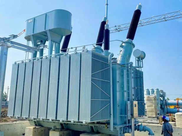
A transformer transfers all of its input electrical energy to the secondary load because the magnetic core has no electrical connection to the windings.False
Real transformers experience core, winding, stray, dielectric, and other losses, so output power is lower than input power. The magnetic core provides magnetic coupling rather than a direct conductive energy path.
What Are Transformer Losses?
Transformer losses are the portions of input power that do not appear as useful output power delivered to the secondary load. In an ideal transformer, input power would equal output power. In a real power transformer, some energy is inevitably dissipated during electromagnetic conversion and physical operation.
The basic efficiency relationship is:
\eta=\frac{P{\text{out}}}{P{\text{in}}}\times100\%
The difference between input and output power represents the total losses:
P{\text{loss}}=P{\text{in}}-P_{\text{out}}
The major loss categories are:
| Loss | Primary Cause | Load Dependence | Main Effect |
|---|---|---|---|
| Core loss | Hysteresis and eddy currents | Mostly independent of load | Continuous energy consumption |
| Copper loss | Winding resistance | Strongly load-dependent | Heat and voltage drop |
| Stray loss | Leakage flux in conductive structures | Load-dependent | Additional heating |
| Dielectric loss | Insulation polarization and leakage | Usually relatively small | Heat and insulation stress |
| Mechanical/acoustic loss | Vibration and magnetostriction | Operating-condition dependent | Noise and small energy dissipation |
For transformer buyers, separating no-load loss from load loss is especially important. No-load loss occurs whenever the transformer is energized, even when the secondary load is minimal. Load loss increases as current increases.
This distinction becomes critical for transformers that remain energized 24 hours a day. A transformer operating at low average load can still consume substantial energy through its core losses. Conversely, a heavily loaded transformer may have relatively small core loss compared with its much larger winding losses.
Efficient transformer selection therefore requires a load profile, not merely a nameplate rating. A 1,000 kVA transformer operating continuously near 80–90% load has a very different loss profile from a 1,000 kVA transformer energized continuously but averaging only 20–30% load.
How Does Core Loss Affect Electrical Energy Transfer?
Core loss occurs because the transformer magnetic core is repeatedly magnetized and demagnetized by alternating magnetic flux. Two principal mechanisms are hysteresis loss and eddy-current loss.
Hysteresis loss is associated with the energy required to repeatedly change the magnetic state of the core material. Electrical steel is selected partly because its magnetic properties allow this loss to be reduced.
Eddy-current loss occurs because the changing magnetic flux induces circulating electrical currents inside the conductive core material. Transformer manufacturers reduce these currents by constructing the core from thin, electrically insulated laminations rather than from one solid piece of steel.
Primary AC voltage
        ↓
Changing magnetic flux
        ↓
 ┌─────────────────┐
 │ Laminated Core  │
 │                 │
 │ Hysteresis loss │
 │ Eddy-current    │
 │ loss            │
 └─────────────────┘
        ↓
Flux links secondary
        ↓
Secondary electrical output
Core loss is generally considered a no-load loss because it exists whenever the transformer is energized. It is therefore particularly important in continuous-duty applications.
Core design affects more than efficiency. Excessive flux density can increase core loss, excitation current, vibration, and acoustic noise. Poor core joints, improper stacking, damaged lamination insulation, or manufacturing deviations can also increase no-load losses.
This is why electrical steel quality and core manufacturing are important purchasing considerations. A manufacturer should control the material grade, lamination thickness, cutting quality, stacking process, joint configuration, clamping, and insulation between laminations.
How Does Copper Loss Affect Energy Transfer?
Copper loss, commonly associated with winding resistance, is caused by current flowing through the electrical resistance of the primary and secondary conductors.
It is approximately proportional to the square of current:
P_{\text{cu}}\approx I^2R
This relationship has major practical implications. If transformer current increases by a factor of two while resistance remains unchanged, the resistive loss increases by approximately four times.
This is why transformer loading has such a strong effect on temperature rise and efficiency.
| Relative Current | Relative Copper Loss* |
|---|---|
| 25% | 6.25% |
| 50% | 25% |
| 75% | 56.25% |
| 100% | 100% |
| 125% | 156.25% |
*Illustrative relative relationship assuming constant winding resistance and (P_{\text{cu}}\propto I^2), not a statement of actual transformer losses.
Copper loss creates heat inside the windings. That heat must then be transferred through insulation, cooling oil or air, radiators, ducts, and external cooling surfaces.
For a transformer manufacturer, conductor selection is therefore a balance among current density, conductor dimensions, winding geometry, mechanical strength, cooling paths, insulation, and cost. Increasing conductor cross-sectional area can reduce resistance, but it may also affect winding dimensions, leakage reactance, material consumption, and manufacturing complexity.
For buyers, guaranteed load-loss values are more meaningful than simply asking whether the transformer uses “high-quality copper.” The complete winding design determines actual loss performance.
Why Does Transformer Load Affect Efficiency?
Transformer efficiency changes with load because different loss mechanisms respond differently to operating current.
At no load, core loss remains present while useful output power approaches zero. Efficiency is therefore not meaningful as a high percentage under very low output conditions.
As load increases, useful output power rises. At moderate load, efficiency generally improves because fixed core losses become smaller relative to output power.
At high load, however, copper and stray losses increase rapidly. Eventually the additional load-dependent losses outweigh the benefit of increased output power, causing efficiency to reach an optimum and then decline.
A simplified conceptual relationship is:
Efficiency
   │
   │          /\
   │         /  \
   │        /    \
   │_______/      \_______
   └─────────────────────── Load
      Light   Optimum   Heavy
This is why transformer designers consider the expected load curve rather than simply designing for maximum nameplate capacity.
For distribution transformers, where equipment may remain energized continuously and operate at varying loads, the balance between no-load and load losses is especially important. For large industrial power transformers, load losses and thermal performance may become increasingly significant because of higher continuous currents.
How Does Heat From Transformer Losses Affect Service Life?
Energy lost in a transformer generally becomes heat. Excessive temperature is one of the most important practical consequences of transformer losses because insulation systems are sensitive to thermal stress.
A transformer does not fail simply because it has losses; all real transformers have losses. The engineering objective is to ensure that the heat generated by those losses can be continuously removed while maintaining winding, insulation, core, and other components within their specified thermal limits.
A typical thermal chain is:
Electrical losses
      ↓
Heat generation
      ↓
Winding/core temperature rise
      ↓
Cooling medium absorbs heat
      ↓
Radiators / air passages / cooling equipment
      ↓
Heat rejected to environment
If the cooling system cannot remove heat fast enough, temperature rises. Prolonged excessive temperature can accelerate insulation aging and reduce expected service life.
This means efficiency and thermal design cannot be separated. A transformer with lower losses generally has less heat to remove, while an adequately designed cooling system ensures that unavoidable losses do not produce excessive temperature rise.
For buyers, site altitude, ambient temperature, enclosure conditions, ventilation, solar exposure, installation location, and expected load profile should be considered alongside transformer loss guarantees.
How Does Leakage Flux Create Stray Losses?
Not all magnetic flux produced by a winding links perfectly with the other winding. Some flux exists outside the intended main magnetic path. This is called leakage flux.
Leakage flux is not necessarily a design defect. A certain amount is unavoidable and can even be intentionally controlled because transformer impedance depends partly on leakage inductance.
However, leakage flux can interact with conductive structural components such as tank walls, clamps, shields, and other metallic parts. These interactions can produce additional circulating currents and heating, commonly grouped under stray losses.
Stray loss becomes particularly relevant in high-current transformers because stronger leakage fields can interact with substantial conductive structures.
Professional transformer design may therefore use appropriate winding geometry, magnetic shields, nonmagnetic structural components, optimized clamping arrangements, and carefully controlled clearances to manage these effects.
The objective is not necessarily to eliminate every leakage field but to control it so that transformer impedance, thermal performance, mechanical strength, and efficiency remain within the intended design limits.
How Does Transformer Efficiency Change With Different Losses?
The relationship can be understood through a simple illustrative example. Suppose a transformer receives 1,000 kW of input power and delivers 990 kW to its load.
Then:
P_{\text{loss}}=1,000-990=10\text{ kW}
and:
\eta=\frac{990}{1,000}\times100\%=99\%
That 10 kW does not disappear. It is primarily converted into heat and other physical losses that must be managed by the transformer cooling and construction systems.
Over continuous operation, even relatively small losses accumulate.
For example, if a transformer continuously dissipates 10 kW:
10\times8,760=87,600\text{ kWh/year}
At an illustrative electricity value of $0.15/kWh, the associated energy value would be:
87,600\times0.15=\$13,140
This is an illustrative calculation, not a universal transformer operating cost. Actual energy prices, operating hours, load conditions, losses, and tariffs vary.
The example demonstrates why buyers should evaluate transformer losses over the expected service life rather than focusing only on initial purchase price.
How Can Manufacturers Reduce Transformer Losses?
Reducing losses requires optimization across the complete transformer design.
For core losses, manufacturers can use appropriate electrical steel, controlled flux density, suitable lamination thickness, high-quality insulation between laminations, and precise core assembly.
For winding losses, designers can optimize conductor cross-section, current density, winding geometry, conductor material, and cooling channels.
For stray losses, winding arrangement and magnetic-field distribution can be optimized while structural materials and shielding are selected appropriately.
For dielectric losses, the insulation system must be carefully selected, processed, dried, assembled, and tested.
| Engineering Area | Loss-Reduction Approach |
|---|---|
| Magnetic core | Optimize steel grade and operating flux density |
| Laminations | Use appropriate thickness and electrical insulation |
| Core joints | Control joint geometry and assembly quality |
| Windings | Optimize conductor size and current density |
| Leakage flux | Optimize winding geometry and magnetic shielding |
| Cooling | Provide adequate heat-transfer paths |
| Insulation | Use an appropriate dielectric system and manufacturing process |
| Manufacturing | Control dimensional accuracy and process consistency |
| Testing | Verify losses, impedance, ratio, resistance, and dielectric performance |
The important manufacturing principle is that lower loss cannot be achieved by changing one component in isolation. Core, winding, insulation, mechanical structure, and cooling must operate as a coordinated system.
How Should Buyers Compare Transformer Losses?
Buyers should request guaranteed or specified values for both no-load and load losses and compare them using the actual project load profile.
A practical evaluation should include:
| Buyer Question | Why It Matters |
|---|---|
| What is the no-load loss? | Determines continuous energy consumption when energized |
| What is the load loss at rated conditions? | Shows current-dependent energy dissipation |
| At what temperature are losses specified? | Winding resistance changes with temperature |
| What is the rated impedance? | Influences voltage regulation and fault current |
| What is the expected load profile? | Determines actual lifetime energy consumption |
| What cooling method is used? | Determines heat-removal capability |
| What is the temperature rise? | Connects losses to thermal performance |
| How are losses factory-tested? | Provides evidence of actual manufactured performance |
| Are test results traceable? | Supports quality assurance and acceptance |
| What efficiency is guaranteed? | Helps evaluate lifecycle operating cost |
Buyers should also be cautious about comparing loss figures from different manufacturers without checking whether the test conditions, rated capacity, temperature reference, and applicable standards are equivalent.
Why Are Factory Tests Important for Transformer Efficiency?
Transformer efficiency is ultimately a measurable engineering characteristic. A manufacturer should therefore verify relevant electrical parameters during factory testing.
Routine transformer testing can include measurements related to winding resistance, voltage ratio, no-load loss, excitation current, load loss, impedance, insulation performance, and other requirements specified by the applicable standard and project documentation.
Loss measurements are particularly valuable because they connect the theoretical transformer design with the actual manufactured product. If measured no-load loss is significantly different from the expected value, engineers may need to investigate the magnetic core, joints, lamination condition, assembly, or test configuration. Similarly, unexpected load-loss results can lead to investigation of winding resistance, conductor dimensions, connections, temperature correction, or stray-loss behavior.
From a supplier perspective, factory testing is therefore not simply paperwork. It is an important quality-control stage that helps confirm whether the transformer can deliver the expected energy-transfer performance.
What Is the Best Way to Select an Efficient Power Transformer?
The most efficient transformer is not necessarily the transformer with the lowest advertised loss in one isolated category. The best transformer is the one whose total loss profile matches the actual operating conditions.
For a continuously energized distribution transformer with low average loading, reducing no-load loss can have substantial lifecycle value. For a heavily loaded industrial transformer, reducing load loss and ensuring adequate cooling may be more important.
The buyer should therefore evaluate:
- Primary and secondary voltage
- kVA/MVA capacity
- 50 Hz or 60 Hz frequency
- Expected average loading
- Peak loading
- Load duration
- No-load loss
- Load loss
- Transformer impedance
- Voltage regulation
- Temperature rise
- Cooling method
- Insulation system
- Installation environment
- Factory testing
- Expected service life
- Lifecycle energy cost
This approach prevents a common purchasing mistake: choosing a transformer based only on the lowest initial quotation.
How Should Buyers Evaluate a Transformer That Transfers Electrical Energy Reliably?
A transformer can meet its rated voltage and kVA specifications yet still perform poorly in real service if its insulation, cooling, magnetic core, windings, impedance, or manufacturing quality is inadequate. Choosing only by price or nameplate capacity can lead to overheating, excessive losses, voltage instability, premature insulation aging, unexpected maintenance, and costly downtime. Reliable transformer selection requires buyers to evaluate the complete energy-transfer system—from electrical design and materials to factory manufacturing, testing, protection, installation, and long-term service support.
Buyers should evaluate a reliable power transformer by checking its voltage ratio, kVA/MVA capacity, frequency, impedance, efficiency, no-load and load losses, temperature rise, insulation system, cooling method, winding and magnetic-core construction, short-circuit strength, factory testing, applicable standards, documentation, and supplier manufacturing capability. The transformer should be selected against the actual load profile and installation environment, not only its nominal rating or purchase price.
The most reliable purchasing process connects every specification to an actual operating requirement. The sections below provide a practical framework that buyers can use when comparing transformer manufacturers, technical quotations, factory capabilities, and final test documentation.
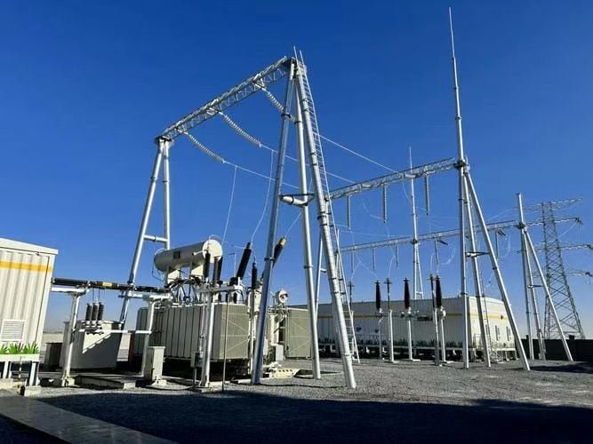
A transformer with the correct rated kVA and voltage is automatically reliable regardless of its construction and operating conditions.False
Transformer reliability also depends on insulation, thermal design, winding and core construction, losses, impedance, mechanical strength, manufacturing quality, testing, installation conditions, and appropriate loading.
What Electrical Specifications Should Buyers Check First?
The first stage of transformer evaluation should establish whether the proposed transformer is electrically compatible with the application. Buyers should verify primary voltage, secondary voltage, frequency, phase arrangement, rated capacity, tap range, impedance, insulation levels, and load characteristics before comparing manufacturers.
The turns ratio determines the basic voltage conversion between the primary and secondary windings. However, the voltage delivered under load can differ from the ideal ratio because of winding resistance and leakage reactance. Therefore, buyers should not evaluate the turns ratio alone. The required secondary voltage should be considered under the expected operating load.
Rated capacity is equally important. A transformer specified at 1,000 kVA is not necessarily suitable for every 1,000 kVA application. The buyer should consider whether the load is continuous, intermittent, cyclical, motor-heavy, nonlinear, or subject to future expansion.
| Parameter | What Buyers Should Verify | Why It Matters |
|---|---|---|
| Primary voltage | Nominal and operating voltage | Determines required insulation and turns |
| Secondary voltage | No-load and expected loaded voltage | Determines equipment compatibility |
| Frequency | 50 Hz, 60 Hz, or specified frequency | Influences magnetic flux |
| Phase | Single-phase or three-phase | Determines winding configuration |
| Capacity | kVA or MVA | Defines allowable apparent-power loading |
| Impedance | Percentage impedance | Affects voltage regulation and fault current |
| Tap range | Tap positions and voltage steps | Compensates for system-voltage variation |
| Insulation level | Applicable dielectric levels | Determines withstand capability |
| Load profile | Average, peak, and duration | Determines thermal and lifecycle requirements |
A reliable supplier should be able to translate these electrical requirements into a coherent transformer design rather than simply supplying a standard model with a similar nameplate.
How Should Buyers Evaluate Transformer Losses?
Transformer losses directly affect efficiency, operating temperature, and lifecycle cost. Buyers should request separate values for no-load loss and load loss rather than relying on a single efficiency percentage.
No-load loss is primarily associated with the magnetic core and exists whenever the transformer is energized. Load loss is primarily associated with winding resistance and increases strongly with current.
A simplified energy balance is:
P{\text{loss}}=P{\text{input}}-P_{\text{output}}
and:
\eta=\frac{P{\text{output}}}{P{\text{input}}}\times100\%
For lifecycle evaluation, buyers should consider how many hours the transformer will remain energized and its expected average loading.
For example, an illustrative transformer with 2 kW of continuous no-load loss would dissipate:
2\times8,760=17,520\text{ kWh/year}
At an assumed electricity value of $0.15/kWh, that represents approximately $2,628 of annual energy cost. This is only an illustration; actual losses, operating hours, electricity prices, and tariffs vary.
For a transformer expected to remain energized for decades, a modest difference in guaranteed losses can therefore become economically significant.
Why Is Thermal Performance Critical to Reliability?
Electrical losses ultimately become heat. If a transformer cannot remove this heat effectively, winding and insulation temperatures rise.
A buyer should therefore evaluate the transformer’s temperature-rise rating, cooling method, ambient-temperature assumptions, altitude, ventilation, and expected loading.
Common cooling arrangements include natural or forced air for dry-type transformers and oil-based cooling systems for oil-immersed designs. The correct method depends on transformer capacity, installation environment, fire-safety requirements, maintenance strategy, and project standards.
Electrical losses
       ↓
     Heat
       ↓
Winding / core temperature
       ↓
Cooling system
       ↓
Heat rejected to environment
       ↓
Stable operating temperature
Thermal design should also match the actual load profile. A transformer that operates near full load for long periods has different thermal requirements from one that experiences short peaks followed by extended low-load periods.
Buyers should ask the supplier to provide temperature-rise information and explain the assumptions used to establish the rating. If the installation has unusually high ambient temperature or poor ventilation, the standard nameplate rating may require additional engineering consideration.
How Should Buyers Inspect the Magnetic Core and Windings?
The magnetic core and windings are the primary electromagnetic components responsible for energy transfer. Their construction has a direct influence on losses, voltage regulation, mechanical strength, and service life.
A quality magnetic core commonly uses suitable electrical steel with controlled lamination thickness and insulation between laminations. Core joints, stacking pressure, clamping, and dimensional accuracy also matter.
The windings require appropriate conductor dimensions, insulation, mechanical support, cooling paths, and short-circuit withstand capability.
For buyers evaluating a manufacturer, useful questions include:
- What electrical-steel grades are used?
- How is core lamination quality controlled?
- How are core joints manufactured and inspected?
- What conductor materials and insulation systems are used?
- How is winding tension controlled?
- How are windings mechanically supported?
- How is moisture removed from the active part?
- How is winding geometry verified?
- How are internal clearances controlled?
These questions help distinguish a genuine transformer manufacturer from a supplier that primarily performs assembly or trading activities.
How Important Is Transformer Insulation?
Insulation is one of the most important reliability systems in a power transformer because electrical failure can cause catastrophic damage and long outages.
The insulation system must withstand normal operating voltage, temporary overvoltages, switching events, lightning impulses, thermal stress, and mechanical forces associated with faults.
For oil-immersed transformers, the dielectric performance of the insulating liquid and solid insulation system must be considered. For dry-type transformers, the resin, varnish, paper, pressboard, or other insulation materials must be appropriate for the voltage and thermal class.
Buyers should review:
| Insulation Evaluation | Buyer Focus |
|---|---|
| Insulation materials | Material type and quality |
| Dielectric strength | Required electrical withstand |
| Clearances | Physical separation between energized parts |
| Creepage distances | Surface leakage path |
| Impulse withstand | Lightning and switching conditions |
| Moisture control | Particularly important for solid insulation |
| Partial discharge | Important for appropriate high-voltage designs |
| Factory dielectric testing | Confirms manufactured insulation integrity |
A supplier should be able to explain the insulation system and provide applicable factory test documentation.
Why Does Transformer Impedance Matter?
Transformer impedance affects both normal operation and fault behavior.
A transformer with lower impedance can generally provide better voltage regulation but may permit higher short-circuit current. Higher impedance can limit fault current but may produce greater voltage drop under load.
Therefore, buyers should select impedance according to the electrical system rather than assuming that the lowest possible value is always preferable.
For industrial systems with large motors, generators, or high prospective fault currents, impedance can have a significant effect on system studies and protection coordination.
The buyer should verify that the proposed transformer impedance is compatible with:
- Short-circuit calculations
- Protection equipment
- Generator characteristics
- Parallel transformer operation
- Motor starting requirements
- Voltage regulation requirements
- Utility interconnection requirements
A technically responsible transformer quotation should clearly identify the impedance value and its applicable tolerance or test basis.
How Should Buyers Evaluate the Cooling System?
Cooling should be evaluated as part of the transformer’s complete thermal system.
For oil-immersed transformers, buyers may encounter different combinations of natural and forced oil or air circulation. For dry-type transformers, cooling can rely on natural or forced air movement.
The appropriate configuration depends on capacity and operating requirements.
Lower capacity / moderate loading
          ↓
Simpler cooling arrangement

Higher capacity / heavier loading
          ↓
Greater heat generation
          ↓
More sophisticated cooling requirements
Buyers should check whether cooling equipment includes adequate radiators, fans, pumps, temperature monitoring, alarms, and control systems where required.
Site conditions are also important. A transformer installed indoors in a restricted electrical room has different cooling requirements from one installed outdoors in a well-ventilated substation.
What Factory Testing Should Buyers Require?
Factory testing provides measurable evidence that the manufactured transformer conforms to its specified design.
Depending on the transformer type and applicable standard, routine tests can include winding resistance, voltage ratio, polarity or phase relationship, no-load loss, excitation current, load loss, impedance, dielectric tests, and other specified measurements.
For buyers, the critical issue is not simply whether the supplier says “100% tested.” The buyer should know what was tested, under what conditions, using which equipment, and whether the results are traceable to the specific transformer.
A useful factory-testing review includes:
| Test Area | What It Helps Verify |
|---|---|
| Winding resistance | Winding and connection condition |
| Turns ratio | Voltage-conversion accuracy |
| No-load loss | Magnetic-core performance |
| Excitation current | Core and magnetic-circuit behavior |
| Load loss | Winding and stray-loss performance |
| Impedance | Electrical system compatibility |
| Dielectric tests | Insulation withstand |
| Temperature-related tests | Thermal design where specified |
| Visual/mechanical inspection | Assembly and construction quality |
A supplier that can explain test procedures and provide clear reports generally offers greater purchasing confidence than one that provides only a generic certificate.
How Can Buyers Evaluate the Transformer Factory?
Factory capability is often more revealing than marketing materials. Buyers should evaluate whether the manufacturer has actual equipment and processes for core fabrication, winding, insulation processing, assembly, drying, testing, and quality control.
Important production areas include:
- Core cutting and processing
- Core stacking and clamping
- Winding machines
- Conductor preparation
- Insulation processing
- Drying and moisture-control equipment
- Tank or enclosure fabrication
- Vacuum processing where applicable
- Oil treatment and filling for oil-immersed designs
- Electrical testing equipment
- Temperature and environmental monitoring
- Final inspection and documentation
A site audit can be especially valuable for large orders or customized power transformers.
Instead of asking only “How many transformers can you produce?”, buyers should ask whether the factory has the specific production processes and testing resources required for their transformer design.
How Does Supplier Experience Affect Reliability?
Transformer reliability depends partly on whether the manufacturer has experience with similar electrical and environmental conditions.
A manufacturer with experience producing transformers for industrial plants may understand motor starting, harmonic loading, short-circuit forces, and demanding duty cycles better than a supplier focused only on simple commercial applications.
Relevant supplier experience can include:
- Similar kVA/MVA ratings
- Similar voltage classes
- Similar cooling systems
- Similar installation environments
- Similar load characteristics
- Export experience
- Customized transformer designs
- Long-term field-service experience
Buyers should request relevant project references when commercially appropriate and verify whether previous products were comparable in technical complexity.
How Should Buyers Compare Price Versus Reliability?
The lowest purchase price does not necessarily represent the lowest total cost.
A useful purchasing model is:
\text{Total Lifecycle Cost}
=
\text{Purchase Cost}
+
\text{Energy Cost}
+
\text{Maintenance Cost}
+
\text{Downtime Risk}
+
\text{Replacement Cost}
A transformer with slightly higher initial cost may be economically preferable if it provides lower guaranteed losses, better thermal performance, stronger insulation, better factory testing, and longer expected service life.
| Evaluation Factor | Low Initial Cost | Higher-Quality Design |
|---|---|---|
| Purchase price | Often lower | May be higher |
| No-load loss | Must verify | Potentially optimized |
| Load loss | Must verify | Potentially optimized |
| Materials | Specification-dependent | Controlled |
| Factory testing | May vary | Comprehensive |
| Documentation | May be limited | Usually detailed |
| Service support | Must verify | Important selection factor |
| Lifecycle risk | Potentially higher | Potentially lower |
The correct decision should be based on the project’s risk tolerance and lifecycle economics.
What Documents Should a Buyer Request?
A professional transformer purchase should generate a complete technical documentation package.
Depending on the project, buyers may request:
- Technical datasheet
- General arrangement drawing
- Nameplate data
- Wiring and control diagrams
- Loss guarantees
- Impedance data
- Insulation specifications
- Cooling-system information
- Material specifications
- Routine test reports
- Type or special test reports when applicable
- Installation instructions
- Operation and maintenance manual
- Spare-parts list
- Warranty information
- Quality documentation
- Applicable compliance certificates
Documentation should identify the actual transformer model or serial number where appropriate.
This traceability becomes valuable throughout the transformer’s service life because maintenance teams can use the original factory data when diagnosing abnormal operating conditions.
What Is a Practical Transformer Reliability Checklist?
Before approving a transformer supplier, buyers can use the following checklist:
| Category | Pass Criteria |
|---|---|
| Electrical rating | Matches actual system requirements |
| kVA/MVA | Adequate for continuous and peak load |
| Turns ratio | Correct for required voltage conversion |
| Frequency | Matches system frequency |
| Impedance | Compatible with fault and regulation requirements |
| Losses | Guaranteed and technically acceptable |
| Magnetic core | Suitable material and controlled construction |
| Windings | Correct conductor, insulation, and mechanical design |
| Cooling | Adequate for actual site conditions |
| Insulation | Appropriate dielectric and thermal performance |
| Factory | Has relevant manufacturing equipment |
| Testing | Appropriate routine and specified special tests |
| Quality system | Controlled processes and traceable records |
| Documentation | Complete and project-specific |
| Service | Warranty and technical support available |
This checklist can be converted into a supplier comparison sheet so that quotations are evaluated using the same technical criteria.
Conclusion
A transformer transfers electrical energy by using electromagnetic induction to convert electrical energy into magnetic energy and then back into electrical energy in the secondary circuit. The primary winding, magnetic core, and secondary winding work together to transfer energy while changing voltage and current levels. For buyers, evaluating core construction, winding design, rated capacity, losses, insulation, cooling, and efficiency is essential for ensuring reliable and efficient energy transfer.
FAQ
Q1: How does a transformer transfer electrical energy?
A1: A transformer transfers electrical energy from one circuit to another through electromagnetic induction rather than through a direct electrical connection between the primary and secondary circuits. Its basic operation depends on a magnetic field that links two or more windings around a magnetic core.
When alternating current flows through the primary winding, it creates a changing magnetic field. The transformer core provides a low-reluctance path that guides much of this changing magnetic flux toward the secondary winding. As the magnetic flux changes, it induces an electromotive force in the secondary winding.
The induced voltage depends strongly on the relationship between the number of turns in the primary and secondary windings. If the secondary winding has more turns than the primary winding, the transformer can produce a higher secondary voltage. If it has fewer turns, the secondary voltage is lower.
Energy is therefore transferred through the changing magnetic field inside the transformer. The primary side receives electrical power, the magnetic system temporarily stores and transfers energy, and the secondary side delivers electrical power to the connected load.
A transformer does not normally generate energy. Instead, it changes electrical characteristics such as voltage and current while transferring power between circuits. In an ideal transformer, input power and output power are approximately equal. In a real transformer, some energy is lost through winding resistance, core losses, leakage flux, and other physical effects.
The transformer core, winding arrangement, insulation system, cooling method, and operating frequency all influence how effectively energy can be transferred. Proper design helps maintain acceptable temperature rise, voltage regulation, efficiency, and insulation performance.
This principle allows transformers to perform essential functions throughout electrical networks. Voltage can be increased for efficient transmission over long distances and reduced later for distribution or equipment use.
The key concept is electromagnetic induction: a changing current creates changing magnetic flux, and that changing flux induces voltage in another winding. This enables electrical energy to move between circuits while maintaining electrical isolation in conventional transformer designs.
Q2: Why does a transformer need alternating current to transfer energy?
A2: A conventional transformer requires a changing magnetic field to induce voltage in its secondary winding, which is why alternating current is normally used. The essential mechanism is electromagnetic induction, and electromagnetic induction requires changing magnetic flux.
When alternating current enters the primary winding, its magnitude and direction continually change. This produces a continuously changing magnetic field in the transformer core. The changing magnetic flux links the secondary winding and produces an induced voltage across its terminals.
If a steady direct current were applied to a conventional transformer primary, the magnetic flux would initially change as the current rises. After the current became steady, however, the magnetic flux would no longer change significantly. Without continuous flux variation, the secondary winding would not maintain an induced output voltage.
Direct current can create serious problems if applied continuously to a conventional transformer. The primary winding may draw excessive current because the normal inductive behavior associated with alternating operation is no longer maintained in the same way. This can cause substantial heating and potentially damage the winding or insulation.
Modern power-electronic systems can nevertheless transfer energy between DC sources and transformers indirectly. For example, an inverter can convert DC into a high-frequency alternating waveform. A transformer can then transfer that energy magnetically, after which additional electronics may convert the output into the required form.
Transformer operating frequency is therefore an important design parameter. Higher-frequency transformers can often use smaller magnetic components, while power-frequency transformers are designed around the characteristics of utility electrical systems.
The requirement for changing flux also explains why transformers are fundamentally different from simple conductive connections. The primary and secondary circuits do not need to be electrically connected for energy transfer to occur. Instead, the magnetic field provides the coupling mechanism.
For practical transformer applications, buyers and engineers should ensure that the transformer's frequency rating matches the intended power source. Operating a transformer at an unsuitable frequency can affect magnetizing current, core losses, temperature rise, and overall performance.
In simple terms, alternating current continuously changes the magnetic field, and that changing magnetic field creates the secondary voltage. Without this changing magnetic flux, a conventional transformer cannot continuously transfer electrical energy through electromagnetic induction.
Q3: How do the primary and secondary windings transfer energy?
A3: The primary and secondary windings transfer energy through their shared magnetic field. They are normally electrically isolated from each other in a conventional transformer, but both interact with the magnetic flux established in the transformer core.
The primary winding is connected to the input electrical source. When an alternating voltage is applied, current flows through the primary winding and establishes magnetic flux in the core. The core concentrates and guides this flux so that it links effectively with the secondary winding.
The secondary winding is connected to the output circuit. Because the magnetic flux through the secondary winding is continually changing, an electromotive force is induced across the secondary terminals. When a load is connected, secondary current flows and electrical power is delivered to that load.
The number of turns in each winding determines the basic voltage relationship. A winding with more turns generally has a higher induced voltage per winding, while a winding with fewer turns has a lower voltage. This allows the transformer to function as either a step-up or step-down device.
Current changes in the opposite direction relative to voltage ratio in an ideal transformer. When voltage is increased, the available current decreases for approximately the same transferred power. When voltage is reduced, the available current increases.
The magnetic core is therefore central to the energy-transfer process. It does not simply serve as mechanical support; it provides a controlled path for magnetic flux and helps improve coupling between the windings.
Transformer construction can vary significantly. Some transformers use laminated steel cores for conventional power-frequency applications, while specialized high-frequency transformers may use other magnetic materials. Winding arrangements also vary according to voltage, capacity, insulation requirements, and application.
Although the primary and secondary windings are magnetically coupled, imperfect coupling means that not all magnetic flux links both windings. Leakage flux contributes to voltage regulation characteristics and can affect transformer performance.
Real transformers also experience winding resistance and core losses. Consequently, the electrical power delivered by the secondary is normally somewhat lower than the power supplied to the primary.
The energy-transfer process can therefore be summarized as a sequence: electrical input creates a changing magnetic field, the core guides the magnetic flux, the changing flux induces secondary voltage, and the secondary circuit converts that induced voltage into useful electrical power for the load.
Q4: How does a transformer increase or decrease voltage while transferring energy?
A4: A transformer changes voltage by using different numbers of turns on its primary and secondary windings. The voltage relationship is primarily determined by the turns ratio between the two windings.
When the secondary winding has more turns than the primary winding, the transformer operates as a step-up transformer. The induced secondary voltage is higher than the primary voltage. This configuration is commonly useful when electrical power needs to be transmitted at a higher voltage.
When the secondary winding has fewer turns than the primary winding, the transformer operates as a step-down transformer. The secondary voltage is lower, making it suitable for distribution networks and equipment requiring a lower operating voltage.
The important point is that increasing voltage does not create additional energy. In an ideal transformer, power remains approximately constant between input and output. Therefore, increasing voltage corresponds to a decrease in current, while reducing voltage corresponds to an increase in current.
For example, if a transformer increases voltage significantly, the current available on the secondary side is correspondingly reduced for a given power level. This relationship is useful in power transmission because higher voltage allows the same power to be delivered with lower current. Lower current can reduce resistive losses in transmission conductors.
The transformer's magnetic core and windings make this voltage conversion possible. Alternating current in the primary produces changing magnetic flux, and that flux induces voltage in both windings according to their respective turn counts.
Practical transformers do not achieve perfect energy transfer. Core losses, winding losses, leakage flux, auxiliary equipment, and other factors reduce output power compared with input power. Voltage regulation also means that the actual secondary voltage can change with loading.
Tap changers may be incorporated into some transformers to adjust the effective winding ratio and help maintain an appropriate output voltage under changing system conditions.
For buyers, the required input and output voltage should be specified clearly, along with rated capacity, frequency, impedance, insulation level, tap requirements, and expected load conditions.
Thus, a transformer changes voltage through its winding ratio while transferring energy through electromagnetic induction. It does not increase the amount of energy available; it converts voltage and current levels to suit the electrical system.
References
IEC 60076-1 — Power Transformers: General
https://webstore.iec.ch/en/publication/588
IEC 60076-2 — Power Transformers: Temperature Rise
https://webstore.iec.ch/en/publication/604
IEC 60076-3 — Power Transformers: Insulation Levels and Tests
https://webstore.iec.ch/en/publication/605
IEC 60076-5 — Power Transformers: Ability to Withstand Short Circuit
https://webstore.iec.ch/en/publication/607
IEC 60076-7 — Loading Guide for Mineral-Oil-Immersed Power Transformers
https://webstore.iec.ch/en/publication/608
IEEE C57.12.00 — General Requirements for Liquid-Immersed Transformers
https://standards.ieee.org/ieee/C57.12.00/6962/
IEEE C57.12.01 — General Requirements for Dry-Type Transformers
https://standards.ieee.org/ieee/C57.12.01/6775/
IEEE C57.12.80 — Terminology for Power and Distribution Transformers
https://standards.ieee.org/ieee/C57.12.80/7006/
IEEE Technology Navigator — Power Transformers
https://technav.ieee.org/topic/power-transformers/
U.S. Department of Energy — Electricity Delivery and Grid Systems
https://www.energy.gov/oe