
Electrical energy must often be transferred between circuits operating at different voltage levels, but directly connecting those circuits can create serious safety, insulation, and system-design problems. A transformer solves this challenge without requiring a direct electrical connection between its primary and secondary circuits. If the electromagnetic transfer mechanism, magnetic core, or winding design is poorly understood, buyers may struggle to evaluate transformer efficiency, losses, insulation requirements, and operating reliability. Understanding how a transformer transfers electrical energy provides the foundation for selecting and specifying the right equipment.
A transformer transfers electrical energy from one circuit to another through electromagnetic induction. Alternating current in the primary winding creates a changing magnetic flux in the transformer core, and this changing flux induces an electromotive force in the secondary winding. Electrical energy is therefore transferred magnetically rather than through a direct conductive connection between the two windings, while the turns ratio determines the resulting voltage and current levels.
The basic principle is straightforward, but practical energy transfer involves several interacting factors, including magnetic flux, winding turns, current, core losses, copper losses, insulation, and transformer efficiency. The following outline explains the energy-transfer process and the key technical considerations buyers should understand when evaluating transformers.
How Does a Transformer Transfer Electrical Energy Through Electromagnetic Induction?
A transformer cannot transfer electrical energy directly from one winding to another through a conductive connection. Instead, it relies on a changing magnetic field. If the magnetic flux is too low, the core is poorly designed, or the windings are incorrectly arranged, the transformer may suffer from excessive losses, overheating, poor voltage regulation, or insulation stress. Understanding electromagnetic induction is therefore essential for understanding how a transformer actually transfers energy and why its core, windings, frequency, turns ratio, and insulation system must be designed together.
A transformer transfers electrical energy through electromagnetic induction by using alternating current in the primary winding to create a changing magnetic flux in the core. This changing flux links the secondary winding and induces an electromotive force (EMF) in it. The induced secondary voltage drives current through the connected load, allowing electrical energy to be transferred magnetically without a direct electrical connection between the primary and secondary circuits.
The process appears simple, but the physical mechanism involves several linked stages: alternating current, magnetomotive force, magnetic flux, Faraday's law, induced EMF, load current, and energy transfer. Understanding these relationships also explains why transformers require an alternating or otherwise time-varying excitation and why transformer design is closely tied to core material, frequency, winding configuration, and magnetic flux density.

A transformer transfers electrical energy directly through a wire connecting the primary and secondary windings.False
In a conventional transformer, energy is transferred through a changing magnetic field produced by the primary winding and linked to the secondary winding. The primary and secondary circuits are normally electrically isolated while remaining magnetically coupled.
What Happens When AC Enters the Primary Winding?
The energy-transfer process begins when an alternating voltage is applied to the primary winding. This voltage produces an alternating current, depending on the winding impedance and the transformer's magnetic characteristics.
The primary winding contains a large number of turns of conductive wire surrounding the magnetic core. Current flowing through these turns produces a magnetomotive force (MMF), which establishes magnetic flux in the core.
The important point is that the magnetic flux is changing with time. A steady DC current would initially create a magnetic field, but after the transient period the flux would no longer continuously change in the way required for sustained transformer action. With AC excitation, the magnitude and direction of the magnetic field continually vary.
The laminated core provides a low-reluctance path for much of this magnetic flux. The objective is to produce strong magnetic coupling between the primary and secondary windings while limiting undesirable losses.
How Does Changing Magnetic Flux Produce Secondary Voltage?
The central physical principle is Faraday's law of electromagnetic induction. When magnetic flux linking a winding changes, an EMF is induced in that winding.
In simplified form, the induced EMF depends on the number of turns and the rate at which magnetic flux changes:
E \propto N\frac{d\Phi}{dt}
where:
- (E) is induced EMF,
- (N) is the number of winding turns,
- (\Phi) is magnetic flux,
- (d\Phi/dt) represents the rate of flux change.
This explains why the secondary winding does not need a direct electrical connection to the primary. Its conductor is exposed to the same changing magnetic flux, so an EMF is induced within the secondary winding.
If the secondary circuit is open, the induced voltage can be measured but essentially no useful load current flows. Once a load is connected, the induced voltage drives current through that load.
This is the fundamental distinction between magnetic coupling and direct electrical conduction.
Why Does the Transformer Core Matter?
The core is responsible for providing an efficient magnetic path between the windings. In power transformers, the core is normally constructed from laminated electrical steel or another suitable magnetic material.
Without an appropriate magnetic core, much of the magnetic field would escape into the surrounding space, reducing coupling and increasing the magnetizing current required for a given operating condition.
Core laminations also help reduce eddy-current losses. Instead of using one large solid conductive magnetic structure, the core is divided into electrically insulated laminations. This restricts circulating currents within the core material.
Core material and thickness must be matched to operating frequency and magnetic requirements. For example, electrical-steel specifications distinguish different grades and thicknesses because magnetic loss and permeability characteristics influence transformer performance.
| Transformer Element | Electromagnetic Function |
|---|---|
| Primary winding | Converts input electrical current into magnetic excitation |
| Magnetic core | Provides a low-reluctance path for flux |
| Secondary winding | Receives changing flux and develops induced EMF |
| Insulation | Electrically separates conductors and winding layers |
| Laminations | Reduce eddy-current losses |
| Cooling system | Removes heat generated by core and winding losses |
| Load | Converts transferred electrical energy into useful output power |
How Does the Turns Ratio Control Voltage?
The number of turns on the primary and secondary windings determines the ideal voltage relationship.
For an ideal transformer, the voltage ratio is proportional to the turns ratio:
\frac{V_s}{V_p}=\frac{N_s}{N_p}
If the secondary has more turns than the primary, the transformer is a step-up transformer. If the secondary has fewer turns, it is a step-down transformer.
For example, if a transformer has 1,000 primary turns and 200 secondary turns, its ideal voltage ratio is 0.2. An input voltage of 10 kV would therefore correspond to approximately 2 kV on the secondary under ideal conditions.
The turns ratio does not mean that energy is multiplied. Rather, voltage and current change in opposite directions so that power is approximately conserved in an ideal transformer.
How Does the Secondary Winding Deliver Energy to a Load?
Once a load is connected to the secondary winding, the induced secondary voltage produces secondary current. This current creates its own magnetic field, which opposes the change that produced it, consistent with Lenz's law.
The increased load current causes the primary side to draw additional current from its source. This is an important feature of transformer energy transfer: the primary does not simply create a fixed magnetic field and the secondary independently receives energy. The electromagnetic system responds dynamically to the connected load.
In practical terms:
Electrical input → primary current → changing magnetic flux → induced secondary EMF → secondary load current → useful electrical output
At the same time, some input energy becomes heat and other losses. Therefore, a real transformer always has efficiency below 100%.
What Happens to Energy in a Real Transformer?
A practical transformer experiences several types of losses.
Core losses include hysteresis and eddy-current losses. These occur whenever the magnetic core is repeatedly magnetized and demagnetized.
Winding losses are mainly resistive losses caused by current flowing through the winding conductors. They increase with current and are commonly associated with (I^2R) heating.
Stray losses can occur when leakage flux induces unwanted currents in structural components or nearby conductive materials.
There are also dielectric and auxiliary losses in some transformer designs.
| Loss Type | Main Cause | Effect |
|---|---|---|
| Hysteresis loss | Repeated magnetic reversal | Core heating |
| Eddy-current loss | Circulating currents in core | Core heating |
| Winding load loss | Winding resistance and current | Copper/conductor heating |
| Stray loss | Leakage flux interacting with conductive parts | Localized heating |
| Dielectric loss | Electrical stress in insulation | Additional heating |
This is why transformer efficiency depends on operating load. A transformer may have relatively small load losses when lightly loaded but still consume energy through its no-load/core losses while energized.
Why Does Frequency Affect Transformer Operation?
Transformer electromagnetic behavior is strongly influenced by frequency. For a given voltage and winding configuration, operating frequency affects the rate at which magnetic flux changes.
If a transformer designed for a particular frequency is operated at an inappropriate lower frequency without corresponding voltage reduction, magnetic flux density can rise and potentially drive the core toward saturation. Saturation can produce excessive magnetizing current, waveform distortion, heating, and possible protection problems.
This is why transformer specifications must clearly define frequency, rated voltage, and magnetic design together.
Frequency also affects core losses. Higher frequency generally changes hysteresis and eddy-current behavior, which is one reason transformer core materials and construction are selected according to the intended operating frequency.
Why Is Electromagnetic Induction Important for Electrical Isolation?
One major advantage of transformer operation is that energy can be transferred without a direct conductive path between the primary and secondary circuits.
This can provide useful electrical isolation in appropriate applications. However, isolation should not be confused with complete protection from every electrical hazard. Insulation, clearances, grounding, shielding, surge protection, and system protection remain necessary.
For critical power transformers, insulation design must account for normal operating voltage as well as transient stresses. Bushings, winding insulation, oil or solid insulation systems, and internal clearances all contribute to safe operation.
How Should Buyers Evaluate a Transformer Based on Electromagnetic Induction?
From a procurement perspective, understanding induction helps buyers evaluate whether a transformer's design is technically appropriate rather than relying only on voltage and capacity.
Important parameters include:
- Primary and secondary voltage
- Rated kVA/MVA
- Frequency
- Turns ratio
- Impedance
- Core material and construction
- No-load loss
- Load loss
- Temperature rise
- Cooling method
- Insulation level
- Vector group
- Tap-changing requirements
- Short-circuit withstand capability
- Factory testing requirements
The manufacturer should also be able to explain how the magnetic design, winding arrangement, insulation system, and cooling system work together.
A technically strong design should provide an efficient magnetic flux path while keeping losses, temperature, leakage flux, insulation stress, and mechanical forces within acceptable limits.
How Does a Transformer Transfer Electrical Energy Through the Magnetic Core?
A transformer does not transfer electrical energy by physically carrying current from the primary winding to the secondary winding. Instead, the magnetic core provides the controlled path for changing magnetic flux that links the two windings. If the core has excessive magnetic loss, poor lamination, insufficient cross-sectional area, or an unsuitable magnetic material, the transformer can develop higher no-load losses, heating, noise, and reduced efficiency. Understanding how the magnetic core works is therefore essential for evaluating transformer efficiency, reliability, and manufacturing quality.
A transformer transfers electrical energy through the magnetic core by converting primary-side alternating current into a changing magnetic flux in the core. The core guides this flux so that it links the secondary winding, where Faraday's law induces a voltage. When a load is connected, secondary current flows and electrical energy is delivered to the load. The magnetic core does not conduct the useful electrical current between windings; it provides the magnetic coupling needed for energy transfer.
For transformer buyers, this distinction is important. The core is not simply a structural support for the windings. Its magnetic properties, geometry, joints, laminations, clamping, and manufacturing accuracy directly affect the transformer's losses, temperature rise, excitation current, acoustic behavior, and long-term reliability.
The magnetic core directly carries electrical current from the primary winding to the secondary winding.False
The core primarily provides a low-reluctance path for changing magnetic flux. Electrical energy is transferred through electromagnetic induction between the windings rather than through conductive current flowing through the magnetic core.
What Is the Magnetic Core in a Transformer?
The magnetic core is the part of a transformer designed to guide magnetic flux between the primary and secondary windings. In a conventional power transformer, the core is generally assembled from thin layers of magnetic electrical steel rather than being made from one solid block.
The primary and secondary windings are positioned around portions of the core so that their magnetic fields are strongly coupled. When alternating current flows in the primary winding, it establishes magnetomotive force (MMF). This produces magnetic flux in the core.
The core's low magnetic reluctance allows much of that flux to follow a controlled path linking both windings.
A simplified energy-transfer chain is:
AC electrical input → primary MMF → changing core flux → secondary induced EMF → load current → electrical output
The core therefore acts as a magnetic coupling path, not as an electrical conductor between the two circuits.
| Transformer Part | Primary Function |
|---|---|
| Primary winding | Creates magnetic excitation from electrical input |
| Magnetic core | Guides changing magnetic flux |
| Secondary winding | Receives linked flux and develops induced voltage |
| Core insulation/lamination | Limits circulating eddy currents |
| Winding insulation | Prevents electrical breakdown |
| Cooling system | Removes heat from losses |
| Clamping structure | Maintains mechanical stability |
How Does the Primary Winding Create Magnetic Flux?
When AC voltage is applied to the primary winding, current flows through its turns. Each turn contributes to the winding's magnetomotive force. The combined MMF establishes magnetic flux through the core.
The important feature is that the flux is alternating rather than constant. It continually changes magnitude and direction in response to the AC excitation.
This changing flux is what makes transformer action possible.
If the primary were supplied with ideal steady DC, the magnetic flux would initially change during energization, producing a transient induction effect. After reaching a steady magnetic condition, however, there would be no continuing periodic flux change capable of producing normal transformer action in the secondary.
This is why conventional transformers are fundamentally associated with alternating or otherwise time-varying excitation.
How Does the Core Guide Magnetic Flux?
Magnetic flux naturally follows paths of lower magnetic reluctance. The transformer core is deliberately designed to provide such a path.
The relationship is analogous to an electrical circuit:
- Electrical voltage drives electrical current.
- Magnetomotive force drives magnetic flux.
- Electrical resistance opposes current.
- Magnetic reluctance opposes flux.
A well-designed core concentrates magnetic flux and reduces leakage between the primary and secondary windings.
This improves magnetic coupling and reduces the magnetizing current required to establish the desired flux.
The core geometry is therefore important. Core-type and shell-type transformer constructions arrange the magnetic path and windings differently, but both aim to achieve efficient magnetic coupling while meeting insulation, cooling, mechanical, and manufacturing requirements.
Why Are Core Laminations Necessary?
A transformer core is electrically conductive to some degree. If it were made from one large solid piece, the alternating magnetic field would induce significant circulating eddy currents within the core.
These currents would waste energy as heat.
Laminating the core divides the magnetic material into thin electrically insulated sheets. The insulation between laminations increases the electrical resistance of potential circulating-current paths and substantially reduces eddy-current losses.
This is one reason transformer manufacturing requires precise control of:
- Lamination thickness
- Insulation between laminations
- Core stacking
- Cutting accuracy
- Joint geometry
- Clamping pressure
- Core grounding
For power transformers, electrical steel is selected according to magnetic-loss, permeability, and manufacturing requirements. Grain-oriented electrical steel is widely used for suitable transformer-core applications because its directional magnetic properties can support efficient flux conduction.
How Does Magnetic Flux Induce Voltage in the Secondary?
The secondary winding is exposed to the changing magnetic flux produced by the primary winding. According to Faraday's law, a changing magnetic flux linking a winding induces an EMF.
In simplified form:
E \propto N\frac{d\Phi}{dt}
where (N) is the number of turns and (\Phi) is magnetic flux.
This relationship explains why the secondary winding can develop a voltage without being electrically connected to the primary winding.
If the secondary circuit is open, the induced voltage exists but little useful current flows. When a load is connected, the induced voltage drives current through the secondary circuit.
The magnetic core is essential because it helps ensure that the changing flux generated by the primary effectively links the secondary.
How Does the Core Affect Transformer Efficiency?
The magnetic core contributes significantly to transformer no-load performance. Two major core-loss mechanisms are hysteresis loss and eddy-current loss.
Hysteresis loss occurs because the magnetic material is repeatedly magnetized and demagnetized during AC operation. Different magnetic materials have different hysteresis characteristics.
Eddy-current loss results from currents induced within the conductive core material. Thin insulated laminations help reduce these currents.
Therefore, core design influences:
- No-load loss
- Excitation current
- Temperature rise
- Overall transformer efficiency
- Acoustic noise
- Operating cost
| Core Characteristic | Potential Effect |
|---|---|
| Magnetic material | Determines permeability and magnetic losses |
| Lamination thickness | Influences eddy-current loss |
| Lamination insulation | Limits circulating currents |
| Core cross-section | Influences flux density |
| Joint quality | Influences local magnetic loss |
| Stacking accuracy | Influences magnetic performance |
| Clamping | Affects mechanical stability and noise |
| Core grounding | Controls unwanted electrical potential |
Why Is Core Flux Density Important?
Flux density is an important design variable because excessive flux density can push the core toward magnetic saturation.
When a core approaches saturation, a relatively small increase in applied voltage or excitation can cause a much larger increase in magnetizing current. This can increase winding stress, heating, waveform distortion, and protection-system concerns.
Core cross-sectional area, winding turns, voltage, and operating frequency must therefore be considered together.
A simplified relationship is that, for a given winding and frequency, increasing voltage or reducing frequency tends to increase the required magnetic flux swing. This is why transformer manufacturers carefully establish the relationship between rated voltage, frequency, number of turns, and core area.
Does the Magnetic Core Actually Carry the Electrical Energy?
This question needs a precise answer.
The core does not carry electrical current from the primary winding into the secondary winding. Instead, it stores and guides magnetic-field energy during the AC cycle while providing strong coupling between the windings.
The primary source supplies electrical power. The electromagnetic field established by the primary transfers energy through the magnetic coupling to the secondary. The secondary then supplies electrical power to the connected load.
In an ideal transformer:
P{\mathrm{in}} \approx P{\mathrm{out}}
In a real transformer:
P{\mathrm{out}} < P{\mathrm{in}}
because energy is consumed by core losses, winding losses, stray losses, dielectric losses, and auxiliary systems where applicable.
The magnetic core is therefore a critical energy-transfer medium, but it is not itself the path of conductive electrical current between the two windings.
How Does the Magnetic Core Work With the Turns Ratio?
The core establishes the common changing magnetic flux, while the number of winding turns determines how much voltage is induced per winding.
For an ideal transformer:
\frac{V_s}{V_p}=\frac{N_s}{N_p}
If the secondary has fewer turns than the primary, the transformer steps voltage down. If it has more turns, the transformer steps voltage up.
For example, consider a transformer with 1,000 primary turns and 200 secondary turns. The turns ratio is 5:1. If the primary voltage is 10 kV, the ideal secondary voltage is approximately 2 kV.
The core makes this possible by establishing the common magnetic flux linking both windings.
Why Does Core Manufacturing Quality Matter?
A theoretically excellent magnetic material can still produce poor transformer performance if manufacturing quality is inadequate.
Core sheets must be cut, positioned, stacked, insulated, and clamped correctly. Poor joints can create localized magnetic flux concentrations and additional losses. Mechanical damage to lamination insulation can increase eddy-current losses.
Core assembly can also influence transformer noise. Mechanical forces associated with alternating magnetization can cause vibration, while core clamping and structural design affect how these vibrations are transmitted.
For this reason, buyers should evaluate a manufacturer's core-processing capability rather than focusing only on the material grade stated in a datasheet.
What Should Buyers Check When Evaluating a Transformer Core?
A practical buyer evaluation should cover both design specifications and manufacturing controls.
Important questions include:
| Buyer Evaluation | What to Verify |
|---|---|
| Core material | Grade and applicable magnetic properties |
| Lamination | Thickness and insulation quality |
| Core construction | Core geometry and joint design |
| Flux density | Appropriate design margin against saturation |
| Core loss | Guaranteed or tested no-load loss |
| Assembly | Stacking, alignment and clamping procedures |
| Grounding | Appropriate core-grounding arrangement |
| Testing | No-load loss, excitation current and other required tests |
| Documentation | Material, design and test records |
Factory testing is especially valuable because it verifies actual transformer performance rather than relying solely on theoretical calculations.
A buyer should pay particular attention to no-load loss and excitation current, because these provide useful information about the magnetic circuit and core behavior.
Here is the next article in the same concise, technical SEO format, focused specifically on the energy-transfer mechanism between primary and secondary windings.
How Does a Transformer Transfer Electrical Energy Between Primary and Secondary Windings?
A transformer transfers electrical energy between two circuits without normally connecting the primary and secondary windings with a conductive path. If the magnetic coupling is weak, the winding arrangement is poorly designed, or the core and insulation systems are inadequate, the transformer can experience higher losses, voltage drop, overheating, and reduced reliability. Understanding how energy moves between the primary and secondary windings helps buyers evaluate transformer design, turns ratio, magnetic coupling, efficiency, insulation, and overall operating performance.
A transformer transfers electrical energy from the primary to the secondary winding through electromagnetic induction. Alternating current in the primary winding creates a changing magnetic flux in the transformer core. This flux links the secondary winding and induces a voltage according to Faraday's law. When a load is connected, the induced secondary voltage drives current through the load, transferring electrical power from the primary circuit to the secondary circuit through magnetic coupling.
The process is based on several connected physical principles: primary excitation, magnetic flux, mutual induction, induced EMF, load current, and energy conservation. Each part of the transformer must be properly designed because efficient energy transfer depends on strong magnetic coupling and controlled electrical, thermal, and mechanical stresses.

Electrical energy is transferred from the primary winding to the secondary winding through a direct conductive connection.False
In a conventional transformer, the primary and secondary circuits are normally electrically isolated. Energy transfer occurs through changing magnetic flux and electromagnetic induction between the windings.
What Happens in the Primary Winding?
Energy transfer begins when an AC voltage is applied to the primary winding. The resulting alternating current produces magnetomotive force around the magnetic core.
Each turn of the primary winding contributes to the magnetic excitation. The combined effect establishes alternating magnetic flux within the core.
The primary winding therefore performs an important conversion:
Electrical energy → electromagnetic excitation → changing magnetic flux
The transformer core then provides a low-reluctance path for much of this magnetic flux, allowing it to link the secondary winding efficiently.
This is why a transformer requires a time-varying magnetic field for continuous energy transfer. A steady magnetic field does not continuously induce voltage in the secondary.
How Does Magnetic Flux Link the Secondary Winding?
The magnetic core concentrates and guides flux produced by the primary winding. Because the secondary winding is positioned around the same magnetic circuit, a significant portion of this changing flux passes through its turns.
Faraday's law explains the next step:
E \propto N\frac{d\Phi}{dt}
where (E) is induced EMF, (N) is the number of turns, and (\Phi) is magnetic flux.
The key concept is mutual induction. The changing magnetic field generated by the primary produces an induced voltage in the secondary.
The secondary therefore does not need a physical wire connected to the primary to develop voltage.
How Does the Secondary Winding Deliver Power to a Load?
If the secondary winding is open, an induced voltage can exist while the secondary current remains very small.
When a load is connected, the induced voltage drives current through the secondary circuit:
Changing flux → induced secondary voltage → secondary current → load power
The secondary current produces its own magnetic effect. According to Lenz's law, this effect opposes the change that produced it.
This opposition causes the primary side to draw additional current from its source. In this way, the primary input responds to the secondary load.
The transformer therefore does not simply “send” a fixed amount of energy from one winding to another. Energy transfer depends dynamically on the connected load.
How Does the Turns Ratio Control Energy Transfer?
The turns ratio determines the voltage relationship between the two windings.
\frac{V_s}{V_p}=\frac{N_s}{N_p}
For example, consider a transformer with 1,000 primary turns and 200 secondary turns. The secondary-to-primary turns ratio is 0.2.
If the primary voltage is 10 kV, the ideal secondary voltage is approximately 2 kV.
This is a step-down transformer.
If the secondary has more turns than the primary, the transformer becomes a step-up transformer.
The important point is that the transformer does not create additional energy when it increases voltage. Under ideal conditions, voltage and current change in opposite directions.
Why Do Primary and Secondary Currents Change in Opposite Directions?
For an ideal transformer, apparent power is approximately conserved:
S_p \approx S_s
For a three-phase transformer, apparent power can be approximated by:
S \approx \sqrt{3}VI
Therefore, if voltage decreases significantly on the secondary side, current increases correspondingly for the same power level.
For example, consider a 1 MVA, 10 kV/400 V three-phase transformer:
| Side | Voltage | Approximate Current |
|---|---|---|
| Primary | 10 kV | 57.7 A |
| Secondary | 400 V | 1,443 A |
This example shows why low-voltage transformer windings may require very large conductors even though the high-voltage winding carries much lower current.
The winding design must therefore account for conductor cross-section, current density, insulation, cooling, mechanical forces, and short-circuit withstand capability.
What Role Does the Magnetic Core Play?
The core provides the magnetic path connecting the primary and secondary windings.
A well-designed core helps maximize the portion of primary-generated flux that links the secondary. Strong magnetic coupling improves transformer performance and reduces unwanted leakage flux.
Core construction also affects losses. Laminated electrical steel is commonly used in power-frequency transformers to reduce eddy-current losses.
The core must also be designed to operate below excessive magnetic saturation. An inappropriate combination of voltage, frequency, winding turns, and core cross-sectional area can produce excessive flux density and magnetizing current.
| Core Characteristic | Influence on Transformer |
|---|---|
| Magnetic material | Determines permeability and core-loss characteristics |
| Lamination thickness | Influences eddy-current losses |
| Core area | Influences operating flux density |
| Joint construction | Affects magnetic losses and local flux distribution |
| Stacking quality | Influences magnetic performance |
| Clamping | Supports mechanical stability and acoustic performance |
What Prevents Energy Transfer From Being 100% Efficient?
A real transformer always has losses.
Core losses occur because the magnetic core is repeatedly magnetized and demagnetized and because alternating flux induces eddy currents.
Winding losses occur because current flowing through winding resistance produces heat.
Additional stray, dielectric, and auxiliary losses may also occur depending on the transformer design.
Consequently:
P{\text{out}} < P{\text{in}}
A transformer with low losses converts a greater proportion of input power into useful output power.
For buyers, this makes no-load loss and load loss important procurement parameters rather than secondary technical details.
Why Is Insulation Important Between the Windings?
Although magnetic coupling transfers energy, the primary and secondary circuits normally require electrical insulation from one another.
The insulation system must withstand normal operating voltage and transient electrical stresses. Depending on the transformer design, this may involve oil, paper, pressboard, solid insulation, bushings, barriers, and controlled clearances.
Poor insulation design or moisture contamination can reduce dielectric strength and increase the risk of electrical breakdown.
This is why winding arrangement and insulation design must be developed together. Increasing the number of turns or changing winding geometry can alter voltage stress, capacitance, leakage reactance, and insulation requirements.
What Is Leakage Flux and Why Does It Matter?
Not all magnetic flux produced by the primary winding links the secondary winding. The portion that does not link both windings is commonly described as leakage flux.
Leakage flux contributes to transformer leakage reactance. This affects voltage regulation and short-circuit behavior.
Some leakage is unavoidable and can be intentionally designed into the transformer. However, excessive leakage can increase voltage drop and reduce coupling.
Therefore, transformer designers balance magnetic coupling, leakage reactance, insulation requirements, mechanical construction, and cooling.
How Should Buyers Evaluate Primary-to-Secondary Energy Transfer?
When purchasing a transformer, buyers should evaluate the complete electromagnetic design rather than focusing only on the turns ratio.
Important specifications include:
- Primary and secondary voltage
- Rated kVA/MVA
- Frequency
- Number of winding turns
- Vector group
- Impedance
- No-load loss
- Load loss
- Temperature rise
- Cooling method
- Insulation level
- Short-circuit withstand capability
- Tap-changing requirements
- Factory testing
Factory tests are particularly valuable because they verify actual transformer characteristics.
| Buyer Evaluation | Why It Matters |
|---|---|
| Turns ratio | Determines voltage transformation |
| Impedance | Influences voltage regulation and fault current |
| No-load loss | Indicates energized core losses |
| Load loss | Indicates losses under load |
| Insulation testing | Verifies dielectric performance |
| Winding resistance | Helps assess winding condition |
| Temperature-rise testing | Verifies thermal design where required |
| Manufacturing inspection | Confirms construction quality |
How Does the Turns Ratio Affect How a Transformer Transfers Electrical Energy?
A transformer can appear to “move” electrical energy from one circuit to another, but the turns ratio determines the voltage and current relationship that makes this transfer practical. If the turns ratio is selected incorrectly, the secondary voltage may be too high or too low, while the resulting current can create excessive conductor heating, poor voltage regulation, or an unsuitable load condition. The solution is to match the transformer turns ratio to the required voltage conversion while checking the corresponding current, power rating, impedance, insulation, and thermal limits.
The turns ratio determines how a transformer transfers electrical energy by controlling the voltage ratio between the primary and secondary windings. For an ideal transformer, the secondary-to-primary voltage ratio equals the secondary-to-primary turns ratio: (V_s/V_p=N_s/N_p). Increasing the secondary turns relative to the primary produces a step-up transformer with higher secondary voltage and lower secondary current; reducing the secondary turns produces a step-down transformer with lower secondary voltage and higher secondary current. Ideally, apparent power is conserved, while practical transformers experience losses caused by winding resistance, core losses, leakage flux, and other non-ideal effects.
Understanding this relationship is important not only for electrical theory but also for selecting, designing, and manufacturing reliable power transformers. The turns ratio affects conductor sizing, insulation requirements, impedance, voltage regulation, efficiency, and the transformer's ability to serve its intended load. The following analysis explains what actually happens inside the transformer and what buyers should verify before selecting transformer equipment.
A transformer can increase secondary voltage without increasing secondary current in the same proportion.False
For an ideal transformer, increasing voltage through a higher turns ratio is accompanied by a corresponding decrease in current so that apparent power remains approximately conserved, subject to practical losses.
What Is the Turns Ratio of a Transformer?
The turns ratio is one of the fundamental design parameters of a transformer. It compares the number of turns on the primary winding with the number of turns on the secondary winding. A winding with more turns develops a greater induced voltage for the same magnetic flux variation, while a winding with fewer turns develops a lower voltage. In simplified form, the voltage ratio follows the turns ratio, so a transformer with 1,000 primary turns and 100 secondary turns has a nominal secondary-to-primary ratio of 0.1. If the primary voltage is 10,000 V, the ideal secondary voltage is approximately 1,000 V. Conversely, if the secondary winding has more turns than the primary, the transformer produces a higher secondary voltage. This is why the same electromagnetic principle can be used for both step-up and step-down power transformers. From a manufacturing perspective, turns ratio is not merely a theoretical number printed on a nameplate. It is established through winding design, conductor selection, insulation coordination, winding arrangement, core dimensions, and factory testing. The actual ratio must also account for the intended operating voltage, frequency, tap position, winding connection, and required voltage regulation. A buyer should therefore avoid evaluating a transformer solely by its nominal voltage ratio. A transformer can have the correct nominal turns ratio but still perform poorly if its winding resistance, leakage reactance, core design, cooling system, or insulation system is inappropriate. For example, a transformer designed for 10 kV/400 V operation must provide the correct low-voltage output under the specified load, not merely achieve 400 V under an ideal no-load calculation. Load current produces voltage drop in the winding impedance, so the actual terminal voltage can differ from the ideal induced voltage. This is especially important in high-current low-voltage transformers, where the secondary winding may carry hundreds or thousands of amperes. In those applications, even a relatively small percentage of impedance can produce meaningful voltage variation and substantial copper losses. Therefore, when assessing a transformer supplier, the turns ratio should be considered together with rated voltage, rated power, frequency, impedance, insulation level, winding material, cooling method, and test data. A technically competent manufacturer should be able to explain how the selected turns ratio connects to the complete electromagnetic and thermal design rather than treating it as an isolated specification.
How Does the Turns Ratio Change Secondary Voltage?
The most direct effect of the turns ratio is voltage transformation. Each winding experiences an induced voltage related to the magnetic flux variation in the common core. When the secondary winding has more turns than the primary, the induced secondary voltage is higher. When it has fewer turns, the secondary voltage is lower.
Consider three simplified configurations:
| Transformer configuration | Primary turns | Secondary turns | Ideal effect |
|---|---|---|---|
| Step-down | 1,000 | 100 | Secondary voltage decreases |
| 1:1 isolation | 1,000 | 1,000 | Voltage approximately unchanged |
| Step-up | 1,000 | 5,000 | Secondary voltage increases |
The important point is that voltage transformation is controlled by the relative number of turns rather than by simply adding or removing electrical power. In an ideal transformer, if the voltage is reduced by a factor of 10, the available current can increase by approximately a factor of 10 for the same apparent power. This is why a distribution transformer can receive relatively high voltage at moderate current and deliver lower voltage at much higher current. The turns ratio therefore determines a fundamental trade-off between voltage and current.
For manufacturers, changing the turns ratio can require substantial changes elsewhere in the transformer. More secondary turns increase conductor length and winding dimensions. Higher voltage may require greater insulation distances, improved dielectric materials, and more careful electric-field control. Lower-voltage high-current windings may require larger conductor cross-sections, multiple parallel conductors, or specialized winding arrangements to manage current density and heat. Consequently, a transformer cannot be reliably designed by changing the number of turns alone. Core cross-sectional area, magnetic flux density, winding window utilization, conductor size, insulation thickness, cooling capacity, and short-circuit mechanical strength must all remain compatible with the revised design.
Why Does Secondary Current Change When the Turns Ratio Changes?
The voltage ratio and current ratio move in opposite directions under ideal transformer conditions. This is a critical concept because electrical energy transfer is not achieved by creating additional power. Instead, the transformer changes the electrical form in which the power is delivered.
For an ideal transformer, apparent power on the primary and secondary sides is approximately equal:
S_p \approx S_s
Therefore, when voltage decreases, current increases correspondingly. For a practical transformer, the output power is slightly lower because part of the input energy is converted into heat, core loss, sound, vibration, and other losses.
For example, consider a 1 MVA, 10 kV/400 V three-phase transformer. The approximate rated currents are:
I_p=\frac{1,000,000}{\sqrt{3}\times10,000}\approx57.7\text{ A}
and
I_s=\frac{1,000,000}{\sqrt{3}\times400}\approx1,443\text{ A}
The secondary current is therefore roughly 25 times the primary current because the secondary voltage is 25 times lower. This illustrates why turns ratio has a major influence on winding construction. The low-voltage winding needs to accommodate a very large current, while the high-voltage winding needs fewer turns but much stronger insulation coordination.
| Parameter | 10 kV side | 400 V side |
|---|---|---|
| Rated apparent power | 1 MVA | 1 MVA |
| Nominal voltage | 10,000 V | 400 V |
| Approx. three-phase current | 57.7 A | 1,443 A |
| Relative voltage | Higher | Lower |
| Relative current | Lower | Higher |
| Main design concern | Insulation and electric stress | Conductor heating and current density |
This trade-off explains why buyers should always evaluate voltage and current together. A transformer advertised only as “10 kV to 400 V” does not provide enough information for proper selection. The manufacturer must also specify the power rating, frequency, impedance, connection arrangement, cooling method, insulation level, temperature-rise limits, and applicable testing requirements.
How Does the Turns Ratio Affect Transformer Impedance?
The turns ratio also affects how impedance is reflected from one side of the transformer to the other. This is particularly important when a transformer is connected to motors, generators, switchgear, converters, distribution systems, or other equipment with significant short-circuit currents.
For an ideal transformer, an impedance connected to the secondary can be reflected to the primary according to the square of the turns ratio. If the turns ratio is changed significantly, the apparent impedance seen by the source can therefore change substantially.
This matters because transformer impedance influences voltage regulation and short-circuit current. A transformer with lower impedance generally allows a larger fault current, assuming the upstream system can supply it. A transformer with higher impedance limits fault current but can produce greater voltage drop under heavy load. The appropriate value is therefore a system-design decision rather than a simple “higher is better” or “lower is better” specification.
From a manufacturing standpoint, leakage reactance and impedance are strongly influenced by winding geometry. Radial and axial distances between windings, winding height, conductor arrangement, and the distribution of turns all affect leakage flux. Manufacturers can therefore adjust winding configuration to achieve the required electrical characteristics while maintaining acceptable mechanical strength and thermal performance.
Buyers should request the guaranteed impedance value and its tolerance, rather than assuming it from the voltage ratio. If the transformer will operate in parallel with another transformer, matching impedance and other characteristics becomes particularly important. Inconsistent impedance can lead to unequal load sharing, excessive circulating current, or unfavorable operating conditions.
Does a Higher Turns Ratio Always Mean Better Energy Transfer?
No. A larger turns ratio is not automatically more efficient. The turns ratio must match the required voltage conversion and the complete transformer design.
Increasing the number of turns can introduce additional conductor length and winding resistance. If the conductor cross-section is not properly selected, copper losses can increase. At the same time, an inappropriate primary-to-secondary relationship can produce excessive magnetic flux density if the winding voltage per turn is not properly matched to the core and operating frequency. Excessive flux density can increase magnetizing current and core loss and may push the core toward saturation.
A reliable transformer design therefore balances several variables:
- Voltage per turn
- Core cross-sectional area
- Operating frequency
- Magnetic flux density
- Winding conductor area
- Current density
- Insulation system
- Leakage reactance
- Cooling capability
- Temperature rise
- Mechanical short-circuit strength
- Required efficiency and voltage regulation
The practical objective is not to maximize the turns ratio. It is to achieve the required voltage transformation with acceptable losses, temperature rise, insulation stress, impedance, physical dimensions, and service life.
How Does the Turns Ratio Affect Transformer Efficiency?
The turns ratio itself does not determine efficiency, but it strongly influences the design conditions that determine efficiency. Transformer efficiency is affected primarily by core loss, winding or copper loss, stray losses, dielectric losses, and auxiliary consumption where applicable.
Core losses occur even when the transformer is lightly loaded because the magnetic core is continuously magnetized and demagnetized while energized. Copper losses increase with winding current and are commonly associated with the square of current. Therefore, the low-voltage winding of a step-down transformer can become a major source of thermal loss because its current is much higher than the high-voltage winding current.
This makes correct conductor sizing essential. If current density is too high, the winding temperature can rise, accelerating insulation aging and reducing service reliability. If conductors are oversized excessively, material costs and winding dimensions may increase without providing a proportional benefit.
A professional manufacturer therefore evaluates the turns ratio together with electromagnetic loading and thermal loading. Factory design calculations can include winding resistance, no-load loss, load loss, temperature rise, impedance, and voltage regulation. Prototype or production-unit testing then verifies whether the manufactured transformer actually meets the specified values.
For buyers, efficiency should be evaluated at realistic operating conditions rather than only at one ideal load point. A transformer may operate for many hours at partial load, where no-load losses become relatively important. Industrial transformers may also experience variable loading, harmonics, ambient-temperature changes, and frequent switching events. The transformer should therefore be selected based on the complete operating profile.
What Happens if the Turns Ratio Is Incorrect?
An incorrect turns ratio can cause several practical problems. If the secondary voltage is too high, connected equipment may experience excessive electrical stress, overheating, insulation damage, or premature failure. If the secondary voltage is too low, motors may draw excessive current, control equipment may malfunction, and system performance may deteriorate.
An incorrect ratio can also create problems when transformers operate in parallel. Even small differences in secondary voltage can produce circulating current between transformers because each unit attempts to establish a slightly different terminal voltage. This is why parallel transformer applications require careful matching of voltage ratio, polarity, phase displacement, impedance, tap position, and other relevant characteristics.
For industrial procurement, the specified turns ratio should therefore be verified through factory testing rather than accepted solely from documentation. Transformer ratio tests can identify incorrect winding connections, manufacturing errors, tap-changer problems, and certain winding faults.
A practical buyer checklist is:
| Verification item | Why it matters |
|---|---|
| Primary rated voltage | Establishes required input condition |
| Secondary rated voltage | Establishes required output |
| Turns ratio | Confirms voltage transformation |
| Tap range | Allows voltage adjustment where required |
| Rated kVA/MVA | Determines allowable apparent power |
| Rated frequency | Determines magnetic operating condition |
| Impedance | Influences voltage regulation and fault current |
| No-load loss | Indicates energized core losses |
| Load loss | Indicates winding and stray losses |
| Temperature rise | Confirms thermal design |
| Insulation level | Confirms dielectric withstand capability |
| Factory test records | Provides evidence of manufactured performance |
How Should Buyers Evaluate a Transformer Turns Ratio?
The best approach is to start with the actual system requirement rather than selecting a turns ratio in isolation. Determine the required primary voltage, secondary voltage, frequency, phase configuration, load type, rated capacity, expected loading profile, ambient conditions, installation environment, and required voltage regulation.
For a simple application, the nominal ratio can be calculated directly from the required voltages. However, the actual design should also consider voltage drop under load. If the system requires a very stable secondary voltage, the transformer may need an appropriate tap arrangement or voltage-regulation strategy.
For larger power transformers, buyers should additionally review transformer impedance, cooling system, winding arrangement, insulation coordination, short-circuit withstand capability, accessories, monitoring devices, and factory acceptance testing.
The manufacturer should be able to provide a clear technical data sheet and explain how the turns ratio relates to the transformer’s complete electromagnetic design. Depending on the application and purchasing specification, useful factory verification may include winding resistance, ratio and phase displacement, no-load loss and current, short-circuit impedance and load loss, dielectric tests, and other applicable routine or type tests.
The most reliable purchasing decision is therefore based on the relationship between turns ratio + voltage + current + power rating + impedance + insulation + cooling + testing, rather than the turns ratio alone.
Below is a concise, original, manufacturer-oriented version that follows the same SEO structure and practical style you have been using.
How Do Transformer Losses Affect How a Transformer Transfers Electrical Energy Efficiently?
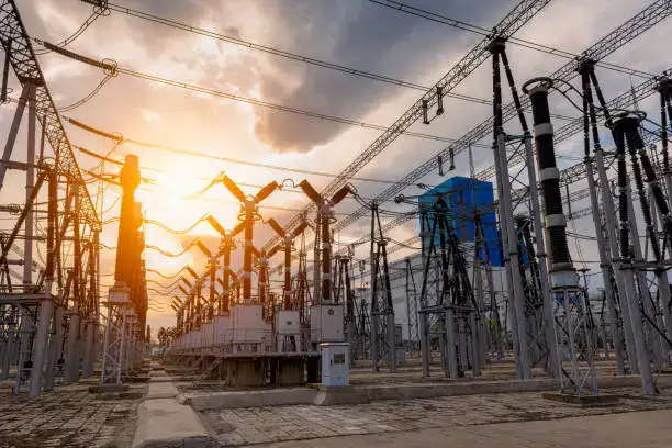
Transformer losses are unavoidable in practical equipment, but poorly controlled losses can reduce efficiency, increase temperature rise, waste electricity, and shorten insulation life. When a transformer operates continuously under load, even a small increase in winding resistance or core loss can become a significant operating cost over many years. The key is not simply to eliminate losses—which is impossible—but to identify where energy is lost, quantify each loss mechanism, and design the transformer so that electrical, magnetic, thermal, and mechanical performance remain balanced throughout its operating range.
Transformer losses reduce the amount of electrical energy delivered to the load because part of the input energy is converted into heat, magnetic losses, stray losses, and other forms of energy. The two principal categories are no-load loss, mainly associated with the magnetic core, and load loss, mainly associated with winding resistance and additional stray effects. Efficient transformer energy transfer therefore depends on low-loss core materials, properly sized windings, optimized magnetic flux density, effective cooling, suitable impedance, accurate manufacturing, and factory testing.
For buyers, transformer efficiency should be evaluated as a complete system characteristic rather than as a single percentage on a datasheet. Understanding each loss mechanism helps explain why transformer size, core material, conductor cross-section, cooling method, operating voltage, load profile, and manufacturing quality all affect the amount of useful electrical energy ultimately delivered.
Transformer losses occur only when the transformer is supplying a load.False
Core-related no-load losses occur while an energized transformer is operating even when the secondary load is very small or disconnected. Load losses increase as winding current increases.
What Are Transformer Losses?
A transformer transfers electrical energy through electromagnetic induction rather than through a direct electrical connection between primary and secondary circuits. Ideally, almost all input power would appear at the output. In a practical transformer, however, some input energy is consumed inside the transformer itself.
The most useful engineering distinction is between no-load loss and load loss. No-load loss exists whenever the transformer is energized and is primarily associated with the magnetic core. Load loss depends strongly on the current flowing through the windings and includes winding resistance losses as well as additional stray losses caused by leakage flux inducing currents in nearby conductive structures.
A simplified loss balance is:
| Loss category | Main source | Load dependence | Main consequence |
|---|---|---|---|
| No-load/core loss | Hysteresis and eddy currents | Relatively low | Continuous energy consumption and heat |
| Winding loss | Conductor resistance | Strongly current-dependent | Heating and efficiency reduction |
| Stray/load loss | Leakage flux and induced currents | Load-dependent | Additional heating |
| Dielectric loss | Insulation system | Usually smaller | Heat and insulation stress |
| Auxiliary loss | Fans, pumps, controls | Operating-condition dependent | Additional energy consumption |
This distinction is especially important for distribution transformers because they can remain energized for thousands of hours, including periods when their electrical load is relatively low. In such applications, no-load loss can accumulate continuously. For large industrial and power transformers, load losses can become much more important during high-load operation.
From a manufacturing perspective, loss optimization begins during electromagnetic design. Engineers select core steel, determine the number of turns, calculate conductor dimensions, establish current density, optimize winding geometry, and evaluate magnetic flux density. These parameters cannot be optimized independently. For example, reducing conductor size may reduce material cost but increase current density and winding loss. Increasing core size may reduce magnetic loading but increase material cost and physical dimensions.
The practical objective is therefore to minimize the lifetime cost of energy losses while maintaining acceptable transformer size, manufacturing cost, thermal performance, voltage regulation, mechanical strength, and reliability.
How Does Core Loss Reduce Transformer Efficiency?
Core loss, also called no-load loss in many transformer applications, occurs because the magnetic core is repeatedly magnetized and demagnetized during normal AC operation. Two major components are hysteresis loss and eddy-current loss.
Hysteresis loss is related to the repeated movement of magnetic domains within the core material. The magnetic material does not respond to changing magnetization with zero energy consumption, so part of the supplied energy becomes heat during each cycle.
Eddy-current loss results from voltages induced within the electrically conductive core material itself. If the core were made as one large solid piece of conductive steel, relatively large circulating currents could develop. Transformer cores therefore use thin insulated laminations to restrict these current paths and reduce eddy-current losses.
Core material selection is consequently a major factor in efficient energy transfer. Modern transformer designs commonly use electrical steels engineered for favorable magnetic properties. Grain-oriented electrical steel, for example, is widely used in transformer cores because its magnetic characteristics can be optimized for the predominant direction of magnetic flux.
Core loss also depends on operating flux density and frequency. If a transformer is operated outside its intended voltage-frequency conditions, magnetic flux can rise beyond the design level. Excessive flux can increase magnetizing current, heating, acoustic noise, and core loss and may create an increased risk of saturation.
Therefore, efficient transformer operation requires more than selecting a low-loss core material. The core material, core geometry, number of winding turns, applied voltage, and operating frequency must work together.
Why Do Transformer Windings Produce I²R Losses?
The windings are made from conductors with finite electrical resistance. Whenever current flows through these conductors, electrical energy is converted into heat.
The fundamental relationship is commonly expressed as:
P_{\mathrm{cu}}=I^2R
This explains why load loss can rise rapidly as transformer loading increases. If winding current doubles while resistance remains approximately constant, the resistive loss increases by approximately a factor of four.
This relationship has direct consequences for transformer manufacturing. A high-current low-voltage winding requires sufficiently large conductor cross-sectional area to keep current density and resistance within acceptable limits. A high-voltage winding, meanwhile, typically contains many more turns and requires a carefully engineered insulation system.
For example, suppose a winding has a resistance of 0.02 Ω and carries 500 A. Its simplified resistive loss is:
P=500^2\times0.02=5,000\text{ W}
That is 5 kW of heat generated in one winding under the assumed conditions. The actual transformer design must account for temperature rise, conductor arrangement, AC resistance effects, and additional stray losses, but the example shows why conductor sizing is critical.
| Winding condition | Current | Resistance | Simplified resistive loss |
|---|---|---|---|
| A | 250 A | 0.02 Ω | 1.25 kW |
| B | 500 A | 0.02 Ω | 5.00 kW |
| C | 750 A | 0.02 Ω | 11.25 kW |
| D | 1,000 A | 0.02 Ω | 20.00 kW |
The table demonstrates the square relationship between current and resistive loss. This is why transformer loading should always be evaluated together with conductor design and thermal performance.
How Does Leakage Flux Create Additional Transformer Losses?
Not all magnetic flux generated by a transformer winding follows the intended magnetic path through both windings. Some flux escapes the ideal coupling path and is called leakage flux.
Leakage flux is important because it contributes to leakage reactance and can induce circulating currents in conductive structural components such as tank walls, clamps, shields, and other nearby metallic parts. These additional effects contribute to stray load losses.
The physical arrangement of the windings strongly influences leakage flux. Winding height, radial spacing, axial arrangement, conductor configuration, and the relative position of high-voltage and low-voltage windings all affect the magnetic field distribution.
A transformer manufacturer therefore needs to optimize winding geometry rather than simply selecting a nominal turns ratio. This is particularly important for high-capacity power transformers where short-circuit forces and leakage fields can become significant.
Well-controlled leakage flux can provide desirable impedance characteristics while limiting unwanted heating. Poorly controlled leakage flux can create localized hot spots and reduce overall efficiency.
For buyers, this is one reason why a transformer should not be evaluated solely according to its voltage ratio and MVA rating. Impedance, load loss, temperature rise, and factory test results provide important evidence of the quality of the electromagnetic design.
How Do Transformer Losses Affect Temperature Rise?
Every watt of internal loss eventually becomes heat that must be transferred away from the active components. As transformer losses increase, the thermal design becomes more demanding.
Temperature rise matters because insulation materials have finite thermal limits. Excessive temperature can accelerate insulation aging, reduce expected service life, and increase the risk of premature failure. Consequently, transformer efficiency and transformer thermal performance are closely connected.
A transformer manufacturer may use oil circulation, radiators, natural convection, fans, pumps, or other cooling arrangements depending on the transformer type and rating. Dry-type transformers use air-based cooling and rely heavily on winding construction, insulation materials, ventilation, and installation conditions.
A useful conceptual relationship is:
Higher loss → more heat → higher temperature rise → greater insulation stress → potentially shorter service life.
This does not mean that a transformer with slightly higher losses will immediately fail. Instead, thermal performance affects long-term reliability. A transformer operating continuously near its thermal limits can experience significantly different aging behavior from one operating comfortably below those limits.
Buyers should therefore review:
- No-load loss
- Load loss
- Temperature rise
- Cooling method
- Ambient-temperature assumptions
- Rated loading conditions
- Overload requirements
- Installation ventilation
- Insulation thermal class where applicable
Efficiency should always be considered together with thermal design.
Why Is Transformer Efficiency Different at Different Loads?
Transformer efficiency is not constant across every loading condition. No-load losses exist whenever the transformer is energized, while load losses increase with current.
At very light load, the fixed core loss can represent a relatively large percentage of the small amount of power delivered to the load. As load increases, that fixed loss becomes a smaller percentage of useful output power, while copper and load-related losses rise.
At sufficiently high loading, the increasing load losses eventually dominate. This creates a typical efficiency curve in which efficiency improves from very light load, reaches a favorable operating region, and then declines as losses increase at heavy load.
A simplified representation is:
| Loading level | Core loss | Load loss | Typical efficiency behavior |
|---|---|---|---|
| Very low | Present | Low | Lower efficiency |
| Moderate | Present | Moderate | Higher efficiency |
| Near optimized load | Present | Higher | Often favorable efficiency |
| Heavy load | Present | Very high | Efficiency may decline |
This is particularly relevant to transformer procurement. A buyer should not automatically choose the transformer with the highest nameplate efficiency without considering the actual load profile.
If a transformer operates most of its life at relatively low loading, reducing no-load loss may have significant economic value. If it operates near rated capacity for long periods, reducing load loss can become more important.
The correct decision therefore depends on how many hours the transformer operates at each loading level, not merely its maximum rated capacity.
How Can Manufacturers Reduce Transformer Energy Losses?
Loss reduction begins with the transformer design but continues through material selection and manufacturing control.
For core loss, manufacturers can use suitable electrical steel, optimized lamination thickness, accurate core cutting, careful joint construction, and appropriate magnetic flux density. For winding loss, engineers can select conductor cross-sectional area and winding geometry to maintain suitable current density and reduce resistance.
Additional design measures can address stray losses and temperature distribution. In larger transformers, numerical electromagnetic and thermal analysis can help identify areas where leakage flux or localized heating may become problematic.
Manufacturing accuracy is equally important. Small dimensional deviations in a high-performance transformer can affect winding geometry, insulation clearances, leakage reactance, or magnetic characteristics. This is why process control and factory testing are essential parts of efficient transformer production.
| Design or manufacturing measure | Main objective | Buyer benefit |
|---|---|---|
| Low-loss core steel | Reduce core loss | Lower continuous energy consumption |
| Optimized flux density | Control magnetic loss | Better efficiency and thermal behavior |
| Adequate conductor area | Reduce resistance | Lower load loss |
| Optimized winding geometry | Control leakage flux | Lower stray losses and better impedance |
| Effective cooling | Remove generated heat | Controlled temperature rise |
| Accurate assembly | Maintain design geometry | Consistent electrical performance |
| Routine testing | Verify manufactured characteristics | Greater confidence in performance |
Efficiency should therefore be viewed as the result of many engineering decisions rather than a single component choice.
How Should Buyers Evaluate Transformer Efficiency?
A buyer should begin by defining the actual operating conditions. Important information includes rated voltage, secondary voltage, kVA or MVA rating, frequency, phase configuration, expected load profile, ambient temperature, installation location, cooling requirements, and future expansion.
The buyer should then request guaranteed loss values rather than relying only on a general efficiency statement. At minimum, it is useful to distinguish no-load loss from load loss.
A practical procurement checklist is:
| Evaluation item | Why it matters |
|---|---|
| No-load loss | Represents continuous energized losses |
| Load loss | Indicates current-dependent internal losses |
| Efficiency curve or operating points | Shows performance under realistic loading |
| Temperature rise | Connects losses to thermal performance |
| Impedance | Affects voltage regulation and fault current |
| Core material | Influences magnetic losses |
| Winding conductor | Influences resistance and thermal loading |
| Cooling system | Determines heat-removal capability |
| Factory test data | Verifies actual transformer characteristics |
| Guaranteed loss values | Provides contractual performance criteria |
For large power transformers, buyers may also require additional type or special tests depending on the project specification and applicable standards.
The most valuable question to ask a manufacturer is not simply, “What is the transformer efficiency?” It is, “What are the guaranteed no-load and load losses, and how were they verified?”
What Is the Long-Term Cost of Transformer Losses?
Transformer losses create an operating cost that continues throughout the transformer's service life. Even when the percentage loss appears small, the accumulated energy consumption can become substantial because transformers often operate continuously.
For example, assume a transformer has an average internal loss of 10 kW and operates for 8,000 hours per year. The annual energy associated with those losses is:
10\text{ kW}\times8,000\text{ h}=80,000\text{ kWh}
This simplified example demonstrates why buyers should consider lifecycle cost rather than purchase price alone.
The economic comparison should include:
Purchase cost + installation cost + energy-loss cost + maintenance cost + expected service life.
A transformer with a higher initial price may be economically attractive if its lower losses produce meaningful electricity savings over many years. Conversely, paying substantially more for an efficiency improvement that has little value under the actual load profile may not be the best engineering decision.
This lifecycle approach is especially important for utilities, industrial plants, commercial facilities, renewable-energy projects, and other installations with long operating periods.
Why Are Factory Tests Important for Transformer Energy Efficiency?
Transformer efficiency is ultimately determined by the characteristics of the manufactured transformer, not merely the design calculation. Factory testing provides evidence that the production unit meets its specified performance.
Depending on the transformer and purchasing specification, routine tests can include measurements related to winding resistance, voltage ratio and phase displacement, no-load loss and current, and short-circuit impedance and load loss. Additional dielectric, temperature, impulse, or special tests may be required for particular applications.
Loss measurement also requires appropriate measurement methods and uncertainty evaluation. Accurate test equipment, controlled procedures, suitable instrumentation, and competent technicians are therefore essential.
A buyer evaluating a transformer factory should examine more than the existence of a test laboratory. It is useful to assess whether the manufacturer can demonstrate:
- Calibrated measurement equipment
- Traceable test procedures
- Documented test records
- Controlled production processes
- Material inspection
- Winding quality control
- Core assembly inspection
- Final electrical testing
- Consistent handling of nonconforming products
A strong factory quality system connects design → materials → manufacturing → testing → final documentation. That chain provides much stronger evidence of transformer efficiency than a marketing claim alone.
Here is a concise, original, buyer-focused article continuing the same transformer SEO series and emphasizing practical evaluation, factory verification, reliability, and lifecycle performance.
How Should Buyers Evaluate a Transformer That Transfers Electrical Energy Reliably?
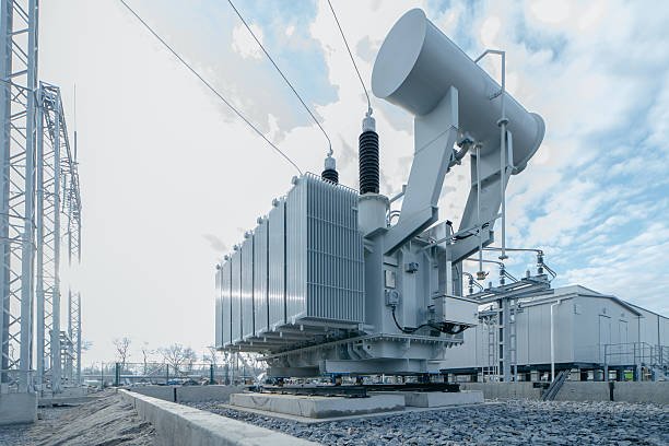
A transformer can have the correct voltage ratio and rated capacity yet still fail to transfer electrical energy reliably over its service life if its insulation, cooling, winding structure, core design, manufacturing quality, or protection system is inadequate. Choosing only from a catalog based on kVA, voltage, and price can therefore create hidden risks such as excessive temperature rise, poor voltage regulation, unexpected losses, insulation deterioration, or premature failure. Buyers should solve this problem by evaluating the transformer as a complete electrical and mechanical system, beginning with application requirements and continuing through design review, materials, production processes, testing, documentation, and after-sales support.
Buyers should evaluate a transformer that transfers electrical energy reliably by verifying its voltage ratio, rated power, frequency, impedance, efficiency, losses, temperature rise, insulation system, cooling method, winding construction, core quality, protection requirements, factory testing, quality control, and long-term service support. The most reliable purchasing decision comes from comparing guaranteed technical performance and test evidence with the actual operating conditions, rather than selecting a transformer based only on purchase price or nameplate voltage.
The transformer should be judged by what happens during normal operation, startup, overload, short-circuit conditions, environmental exposure, and long-term aging. The following framework provides a practical way for buyers to assess whether a transformer manufacturer can deliver dependable electrical energy transfer rather than merely supply a correctly labeled product.
A transformer with the correct rated voltage and kVA is automatically reliable.False
Reliable transformer operation also depends on insulation, thermal design, impedance, losses, winding construction, core quality, manufacturing control, testing, installation conditions, and maintenance.
What Application Requirements Should Buyers Define First?
The first step in transformer evaluation is to define the electrical duty precisely. A transformer should not be selected before the buyer knows the primary voltage, secondary voltage, rated frequency, phase configuration, required capacity, load characteristics, installation environment, and expected loading profile.
For example, a transformer serving a stable resistive load has a different operating profile from one supplying motors, variable-frequency drives, rectifiers, welding equipment, or renewable-energy converters. Loads containing harmonics can increase additional heating, while motors can create significant starting currents. A transformer designed without considering these conditions may experience greater temperature rise or voltage deviation than expected.
The basic specification should include:
| Parameter | What the buyer should define | Why it matters |
|---|---|---|
| Primary voltage | Nominal and allowable range | Determines input winding design |
| Secondary voltage | Required operating voltage | Determines voltage transformation |
| Rated power | kVA or MVA | Determines thermal and electrical capacity |
| Frequency | 50/60 Hz or project-specific | Affects magnetic operation |
| Phase | Single- or three-phase | Determines winding configuration |
| Load type | Resistive, motor, rectifier, VFD, etc. | Influences current and losses |
| Load profile | Continuous, variable, intermittent | Affects lifecycle losses |
| Ambient conditions | Temperature, altitude, environment | Influences cooling |
| Installation | Indoor, outdoor, enclosure, space | Determines construction requirements |
| Regulation requirement | Permitted voltage variation | Influences impedance and design |
A professional transformer supplier should be able to convert these application parameters into a detailed technical specification.
How Should Buyers Evaluate Transformer Voltage and Turns Ratio?
The voltage ratio is one of the first characteristics buyers normally check, but it should not be evaluated in isolation. The nominal turns ratio determines the theoretical relationship between primary and secondary voltage, while actual terminal voltage also depends on transformer impedance, load current, winding resistance, and tap position.
A buyer should therefore distinguish between no-load voltage and loaded secondary voltage. A transformer may produce the expected voltage when lightly loaded but experience a larger voltage drop under heavy load if its impedance or winding design is unsuitable.
For applications requiring stable output voltage, buyers should investigate whether the transformer includes appropriate taps or voltage-regulation provisions. The available tap range, tap positions, and method of adjustment should be clearly documented.
For transformers intended to operate in parallel, voltage ratio matching becomes particularly important. Differences in ratio, phase displacement, polarity, or impedance can create circulating current or unequal load sharing.
The evaluation should include:
- Primary rated voltage
- Secondary rated voltage
- Voltage ratio
- Tap range
- Tap position
- Phase displacement
- Polarity
- Rated frequency
- Voltage tolerance
- Voltage regulation
The supplier should also explain how these values are verified during factory testing.
Why Are Transformer Losses Important for Reliable Energy Transfer?
Energy efficiency is directly connected to reliable operation because internal losses become heat. The principal categories are core/no-load loss and load-related loss.
Core losses occur when the transformer is energized, while winding losses increase with current. Additional stray losses can arise from leakage flux interacting with conductive structural components.
A simplified winding-loss relationship is:
P_{\mathrm{loss}}\approx I^2R
This means that current has a particularly strong effect on resistive losses. If current increases substantially, the resulting heat can increase rapidly.
For buyers, loss evaluation should therefore separate the main loss components:
| Loss | Operating condition | Buyer concern |
|---|---|---|
| No-load/core loss | Transformer energized | Continuous energy consumption |
| Load loss | Transformer carrying current | Heating and efficiency |
| Stray loss | Usually increases with load | Localized heating |
| Dielectric loss | Insulation energized | Long-term insulation performance |
| Auxiliary loss | Fans, pumps, controls | Additional operating consumption |
A low-loss transformer can reduce both energy expenditure and thermal stress. However, buyers should evaluate losses at realistic operating conditions rather than relying on a single headline efficiency figure.
How Should Buyers Assess Transformer Thermal Performance?
A transformer cannot transfer electrical energy reliably if the heat generated by its losses cannot be removed effectively. Thermal performance should therefore be treated as a primary reliability parameter.
Buyers should review the specified temperature rise, cooling method, ambient-temperature assumptions, and rated loading conditions. For oil-immersed transformers, the tank, radiators, oil circulation, and optional fans or pumps all contribute to heat removal. For dry-type transformers, ventilation, insulation materials, winding construction, and installation clearance are particularly important.
The relationship is straightforward:
Electrical losses → heat generation → temperature rise → insulation aging → service-life impact.
This is why a supplier should provide clear temperature-rise information instead of simply stating the transformer capacity.
A buyer should also consider whether the transformer will operate continuously near rated capacity. If significant overload or future capacity expansion is expected, the thermal design should be evaluated accordingly.
What Role Does the Transformer Insulation System Play?
The insulation system separates conductors operating at different electrical potentials and prevents destructive electrical breakdown. Its quality is therefore fundamental to safe energy transfer.
Buyers should evaluate insulation materials, clearances, creepage distances where applicable, insulation levels, winding-to-winding insulation, winding-to-ground insulation, and the expected environmental conditions.
Moisture, contamination, excessive temperature, electrical stress, and mechanical movement can all affect insulation performance.
The insulation system must also be compatible with the transformer's voltage class and cooling arrangement. Increasing the operating voltage does not simply require adding more turns; it can require significant changes to insulation structure and electric-field control.
For this reason, buyers should request detailed insulation specifications and appropriate dielectric test results rather than accepting a general statement that the transformer is “high insulation.”
How Important Are Core and Winding Construction?
The magnetic core and windings are the transformer's main active components. Their construction has a direct influence on efficiency, temperature rise, voltage regulation, mechanical strength, and service life.
For the core, buyers should consider:
- Electrical-steel grade
- Lamination thickness
- Core-joint construction
- Core assembly accuracy
- Magnetic flux density
- Core grounding arrangement
For the windings, buyers should consider:
- Copper or aluminum conductor selection
- Conductor cross-sectional area
- Current density
- Winding arrangement
- Insulation structure
- Mechanical bracing
- Short-circuit withstand capability
A high-current low-voltage winding may require substantial conductor area, while a high-voltage winding requires careful insulation engineering. These requirements must be balanced with the desired transformer impedance and physical dimensions.
A reliable manufacturer should be able to explain how the core and winding designs were selected for the specified voltage, capacity, frequency, and load profile.
Why Should Buyers Evaluate Transformer Impedance?
Transformer impedance affects voltage regulation, fault current, and load behavior. It is therefore an important link between electrical energy transfer and system protection.
If impedance is too low, the transformer may permit very high short-circuit current. If impedance is too high, voltage drop under load can become undesirable.
The correct impedance is therefore application-dependent.
| Impedance consideration | Potential effect |
|---|---|
| Lower impedance | Higher available fault current |
| Higher impedance | Greater limitation of fault current |
| Appropriate impedance | Balanced voltage regulation and system performance |
| Poorly matched parallel impedance | Unequal load sharing or circulating current |
When comparing suppliers, buyers should request guaranteed impedance values and applicable tolerances. For parallel operation, impedance matching should be treated as a critical specification rather than a secondary detail.
How Can Buyers Verify Factory Manufacturing Capability?
A transformer datasheet shows the intended product, but factory capability determines whether that design can be manufactured consistently.
Buyers should examine the manufacturer's production equipment and processes, including:
- Core cutting and assembly equipment
- Winding machines
- Conductor preparation equipment
- Insulation processing
- Vacuum drying equipment where applicable
- Tank fabrication
- Welding and leak-control processes
- Oil filling and treatment equipment for oil-immersed units
- Assembly and finishing areas
- Electrical testing facilities
The objective is not simply to find a large factory. Buyers should determine whether the factory's equipment is appropriate for the required transformer size and technical specification.
A manufacturer producing small distribution transformers may not have the same capability required for large MVA-class power transformers. Production capacity should therefore be evaluated against the specific product being purchased.
What Factory Tests Should Buyers Request?
Factory testing provides one of the strongest forms of evidence that the manufactured transformer meets its specification.
Depending on transformer type, rating, applicable standards, and the purchasing contract, buyers may review tests related to:
- Winding resistance
- Voltage ratio and phase displacement
- No-load loss and current
- Short-circuit impedance and load loss
- Dielectric performance
- Insulation resistance
- Temperature-related performance where specified
- Special or type tests where required
The exact testing program should be agreed upon before production.
A useful procurement table is:
| Factory verification | What it helps confirm |
|---|---|
| Ratio test | Correct voltage transformation |
| Winding resistance | Winding electrical condition |
| No-load test | Core loss and magnetizing behavior |
| Short-circuit/load-loss test | Impedance and load losses |
| Dielectric tests | Insulation withstand capability |
| Visual/mechanical inspection | Assembly quality |
| Oil-related tests where applicable | Insulating-medium condition |
| Special/type tests | Application-specific performance |
Buyers should request signed test reports associated with the actual transformer rather than generic laboratory examples.
How Should Buyers Evaluate Quality Control and Materials?
Transformer reliability begins before assembly. Core steel, copper or aluminum conductors, insulation materials, transformer oil where applicable, gaskets, bushings, and other components can all influence final performance.
A strong manufacturer should have procedures for incoming-material inspection, identification, storage, process control, final inspection, and traceability.
Buyers should ask whether important materials can be traced to certificates or inspection records. They should also determine how nonconforming materials and production deviations are controlled.
A practical supplier assessment looks at the entire chain:
Raw materials → component inspection → controlled manufacturing → in-process inspection → final assembly → electrical testing → final documentation.
This approach is more meaningful than evaluating quality solely from a certificate displayed on a website.
How Do Cooling, Protection, and Accessories Affect Reliability?
The transformer itself is only one part of the operating system. Monitoring and protection accessories can help detect abnormal conditions before they develop into serious failures.
Depending on transformer type and application, relevant equipment may include temperature indicators, pressure-related devices, oil-level indicators, Buchholz relays, pressure-relief devices, cooling controls, surge protection, and monitoring systems.
The correct accessory package depends on transformer construction and project requirements. Buyers should avoid adding accessories without understanding their purpose, but they should also avoid removing necessary protection merely to reduce purchase price.
A reliable specification should clearly define which accessories are required, which are optional, and how alarms or protection signals integrate with the plant or grid protection system.
How Should Buyers Compare Transformer Suppliers?
Supplier comparison should use a structured scorecard rather than focusing on the lowest quotation.
| Evaluation category | Suggested buyer question |
|---|---|
| Electrical design | Does the design match voltage, capacity, frequency, and load? |
| Loss performance | Are no-load and load losses guaranteed? |
| Thermal design | Is temperature rise appropriate? |
| Insulation | Is the insulation system suitable for the voltage and environment? |
| Mechanical design | Can the transformer withstand expected short-circuit forces? |
| Manufacturing | Does the factory have appropriate equipment and processes? |
| Testing | Can the supplier perform and document required tests? |
| Quality control | Are materials and processes traceable? |
| Delivery | Can production schedules support the project? |
| Service | Is technical support available after installation? |
| Documentation | Are drawings, test reports, manuals, and certificates complete? |
| Lifecycle value | Do efficiency and reliability justify the total cost? |
This scorecard helps prevent a common procurement mistake: selecting the transformer with the lowest initial price while overlooking energy losses, maintenance requirements, delivery risk, or inadequate testing.
What Should Buyers Request Before Placing an Order?
Before issuing a purchase order, buyers should request a complete technical package. Depending on project complexity, this may include:
- Transformer technical datasheet
- General arrangement drawing
- Electrical schematic or connection diagram
- Rated voltage and turns-ratio information
- Rated kVA/MVA
- Impedance specification
- Guaranteed no-load and load losses
- Temperature-rise data
- Insulation specifications
- Cooling arrangement
- Accessory list
- Factory test plan
- Routine test reports after production
- Material certificates where required
- Installation and maintenance documentation
- Warranty conditions
- Spare-parts and service information
The buyer should also define acceptance criteria before manufacturing begins. This avoids disagreements later about whether a measured loss, impedance, temperature rise, dimensional characteristic, or accessory configuration is acceptable.
How Should Buyers Evaluate Reliability Over the Transformer Lifecycle?
The best transformer is not necessarily the cheapest transformer to purchase. It is the transformer that provides the required electrical performance with acceptable losses, thermal stress, maintenance requirements, and failure risk throughout its expected service life.
A useful lifecycle perspective is:
Initial purchase cost + installation cost + energy losses + maintenance + downtime risk + replacement cost.
For continuously energized equipment, even modest no-load losses can accumulate year after year. For heavily loaded equipment, load losses and temperature rise can become major considerations.
Buyers should therefore compare competing designs using the expected load profile rather than only the rated capacity.
If two transformers have similar purchase prices but one has substantially lower guaranteed losses and stronger factory verification, its lifecycle economics may be significantly better. Conversely, if a premium transformer has features that provide little benefit for the actual application, the additional investment may not be justified.
Conclusion
A transformer transfers electrical energy by converting electrical energy in the primary winding into a changing magnetic field and then converting that magnetic energy back into electrical energy in the secondary winding. This process enables voltage transformation while maintaining the same AC frequency, with the magnetic core and winding design determining how efficiently and reliably energy is transferred. For buyers, evaluating core materials, winding construction, losses, cooling, insulation, rated capacity, and efficiency is essential to achieving dependable long-term performance.
FAQ
Q1: How does a transformer transfer electrical energy between circuits?
A1: A transformer transfers electrical energy between circuits through electromagnetic induction. Unlike a direct electrical connection, a conventional transformer uses a magnetic field to couple the primary and secondary windings.
When alternating current enters the primary winding, it produces a changing magnetic field around the winding. The transformer's magnetic core guides this changing magnetic flux through the core and toward the secondary winding. As the magnetic flux changes, it induces a voltage in the secondary winding.
The secondary circuit can then deliver electrical energy to a connected load. In this process, energy moves from the electrical circuit connected to the primary winding into the magnetic field and then back into electrical form in the secondary circuit.
The voltage produced on the secondary side depends mainly on the relationship between the number of turns in the two windings. A secondary winding with more turns than the primary can produce a higher voltage, while a winding with fewer turns can produce a lower voltage.
Current changes in the opposite direction. When voltage is increased, the secondary current generally decreases for approximately the same transferred power. When voltage is reduced, the available secondary current generally increases.
A real transformer cannot transfer energy with perfect efficiency. Some energy is lost through winding resistance, magnetic effects, leakage flux, and other operating factors. These losses appear primarily as heat and can influence the transformer's temperature.
The core and winding design are therefore critical. The magnetic core needs to support efficient flux transfer, while the windings must be properly insulated and mechanically supported. Larger power transformers also require appropriate cooling systems to remove heat generated during operation.
The frequency of the AC supply is another important factor. Transformer operation depends on changing magnetic flux, so a conventional transformer is designed around a specified frequency and operating range.
This energy-transfer process allows transformers to connect electrical circuits operating at different voltage levels without requiring a direct conductive connection between the two sides. It is the fundamental reason transformers are used throughout generation, transmission, distribution, and industrial power systems.
Q2: Why is electromagnetic induction essential to transformer energy transfer?
A2: Electromagnetic induction is essential because it provides the mechanism that converts electrical energy in the primary winding into magnetic energy and then induces electrical energy in the secondary winding.
The process begins with alternating current flowing through the primary winding. Because the current changes continuously, the magnetic field produced by the winding also changes. The magnetic core concentrates and directs this changing magnetic flux.
When the changing flux links with the secondary winding, it induces an electrical voltage in that winding. If an external circuit is connected to the secondary, the induced voltage causes current to flow through the load.
This means the transformer does not need a physical electrical connection between the primary and secondary circuits for energy transfer. The magnetic field provides the coupling mechanism.
The effectiveness of this process depends heavily on how well the magnetic flux links the two windings. Transformer cores are designed to provide a controlled magnetic path, while winding arrangements are designed to achieve the required voltage ratio and electrical performance.
Electromagnetic induction also explains why conventional transformers operate with alternating current. A continuously changing current produces the changing magnetic flux required to induce voltage in the secondary winding. A steady direct current does not provide the same continuous induction process under normal transformer operation.
The strength and variation of the magnetic flux also affect transformer behavior. Excessive magnetic flux can push the core toward saturation, potentially increasing current and losses. Transformer designers therefore select core dimensions, materials, winding characteristics, and operating voltage carefully.
The insulation system is equally important because the primary and secondary windings can operate at substantially different electrical potentials. Adequate insulation allows magnetic coupling to occur while maintaining electrical separation.
In power transformers, electromagnetic induction works together with thermal, mechanical, and insulation systems. The electromagnetic principle provides energy transfer, while the rest of the transformer design ensures that the transfer can occur safely and efficiently under the specified operating conditions.
Therefore, electromagnetic induction is not simply one feature of transformer operation. It is the fundamental physical process that allows a transformer to transfer electrical energy from one circuit to another while changing voltage and current characteristics.
Q3: What role do the transformer core and windings play in energy transfer?
A3: The core and windings form the central active system responsible for transferring energy through a transformer. The windings handle the electrical side of the process, while the core provides an efficient path for the changing magnetic flux.
The primary winding receives electrical energy from the input circuit. When AC flows through it, the winding generates a changing magnetic field.
The magnetic core guides this changing magnetic flux. A well-designed core helps concentrate the flux so that it links effectively with the secondary winding. Core construction and material selection influence losses, temperature rise, efficiency, and operating noise.
The secondary winding receives the magnetic coupling created by the changing flux. The changing flux induces a voltage in the secondary winding, allowing energy to be delivered to the connected load.
The number of turns in each winding determines the basic voltage relationship. A higher number of secondary turns generally produces a higher secondary voltage, while fewer secondary turns generally produce a lower voltage.
Winding construction must also account for current. A winding carrying higher current requires appropriate conductor dimensions and thermal design. Large power transformers may use complex winding arrangements to withstand short-circuit forces, thermal stress, and high electrical fields.
Insulation between winding layers and between windings and the core is another critical consideration. Without adequate insulation, the electrical separation required for safe transformer operation could be compromised.
The physical arrangement of the windings also affects leakage reactance and other electrical characteristics. Engineers therefore optimize winding geometry rather than treating the number of turns as the only design variable.
The core and windings also interact thermally. Electrical resistance in the windings produces heat, while magnetic losses occur within the core. The resulting heat must be transferred away through the transformer's cooling system.
For a power transformer, successful energy transfer therefore depends on the coordinated design of the core, windings, insulation, and cooling system. The core provides the magnetic pathway, the windings establish electrical input and output, and the insulation and cooling systems allow these components to operate reliably.
Q4: Does a transformer transfer power without losing energy?
A4: No transformer transfers energy with absolutely zero loss in practical operation. A well-designed transformer can achieve high efficiency, but some of the input energy is inevitably converted into heat, sound, or other forms of loss.
One major source of loss is winding loss. Electrical conductors have resistance, so current flowing through the windings produces heat. The amount of this loss is strongly influenced by the current and the resistance of the winding conductors.
Another source is core loss. The changing magnetic field causes energy losses within the magnetic core. These losses are associated with the behavior of the magnetic material during repeated changes in magnetic flux.
Transformers can also experience additional losses caused by leakage flux and induced currents in nearby conductive structural components. These effects become important in the design of larger and higher-capacity transformers.
Because these losses produce heat, transformer cooling is essential. Depending on the design, heat may be removed through natural air circulation, forced air, insulating liquid, radiators, pumps, fans, or combinations of these methods.
Efficiency varies with operating conditions. A transformer operating at different load levels will experience different proportions of no-load and load-related losses. Consequently, buyers should consider the expected load profile rather than looking at a single efficiency figure in isolation.
Transformer design can reduce losses through appropriate magnetic materials, conductor selection, core construction, winding design, and cooling arrangements. However, minimizing one type of loss may affect cost, size, temperature rise, or other performance characteristics.
For large power transformers, even small efficiency differences can matter because these assets can operate continuously for many years. Energy losses accumulated over the transformer's service life can represent a substantial operating cost.
The distinction between input power and output power is therefore important. The transformer transfers most of the supplied electrical energy to the secondary side, but a portion is consumed by the transformer's own operating losses.
In practical terms, the goal is not to eliminate all losses, which is impossible, but to design and operate the transformer so that losses remain within acceptable limits while meeting reliability, capacity, voltage, thermal, and economic requirements.
References
IEC 60076-1 — Power Transformers: General
https://webstore.iec.ch/en/publication/588
IEC 60076-2 — Power Transformers: Temperature Rise
https://webstore.iec.ch/en/publication/604
IEC 60076-3 — Power Transformers: Insulation Levels and Dielectric Tests
https://webstore.iec.ch/en/publication/605
IEC 60076-5 — Power Transformers: Ability to Withstand Short Circuit
https://webstore.iec.ch/en/publication/607
IEC 60076-7 — Loading Guide for Mineral-Oil-Immersed Power Transformers
https://webstore.iec.ch/en/publication/608
IEEE C57.12.00 — General Requirements for Liquid-Immersed Transformers
https://standards.ieee.org/ieee/C57.12.00/
IEEE C57.12.01 — General Requirements for Dry-Type Transformers
https://standards.ieee.org/ieee/C57.12.01/
IEEE C57.12.80 — Terminology for Power and Distribution Transformers
https://standards.ieee.org/ieee/C57.12.80/
IEEE Transformers, Regulators and Reactors Standards
https://technav.ieee.org/topic/transformers-regulators-and-reactors-c57/
U.S. Department of Energy — Electricity Delivery and Grid Systems
https://www.energy.gov/oe