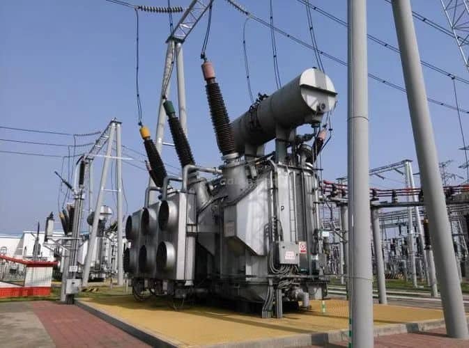
Power transformers are at the core of modern electric power systems, serving as critical links between generation, transmission, and distribution networks. Without them, efficient and reliable long-distance electricity transmission would not be possible. Their ability to step voltage levels up or down enables grid stability, minimizes power losses, and ensures electricity reaches homes, industries, and infrastructure safely. This article explores the vital role power transformers play in enabling a stable, scalable, and efficient energy network.
How Do Power Transformers Facilitate Long-Distance Power Transmission?
Delivering electrical energy from generation sites to distant cities and industrial centers requires minimizing losses and ensuring voltage stability over vast distances. Power transformers are the essential enablers of this process. Without them, transmission efficiency would drop drastically due to resistive losses and voltage drop along the power lines.
Power transformers enable long-distance transmission by stepping up voltage levels at generation points (reducing current and losses during transmission) and stepping down voltage at distribution substations for safe end-user delivery. High-voltage transmission dramatically reduces I²R losses, and transformers provide the scalable voltage control needed to operate and stabilize the grid.
Their ability to adjust voltage levels safely and reliably is what allows modern power systems to span hundreds—even thousands—of kilometers.
Power transformers are not needed for long-distance power transmission.False
Transformers are essential in stepping voltage up for efficient transmission and stepping it down for safe distribution to consumers.
⚡ Why High Voltage Transmission Is Necessary
| Transmission Parameter | Impact on Efficiency |
|---|---|
| Current (I) | Causes I²R (resistive) power losses |
| Voltage (V) | Higher V → Lower I for the same power (P = VI) |
| Line Losses | Drop sharply as current decreases |
| Conductor Size | Can be smaller for high voltage, reducing cost |
Example: A 100 MW line at 11 kV carries 9,090 A → massive I²R losses. At 220 kV, current drops to 455 A—losses fall 400×.
🔄 Transformer Role in Transmission Chain
| Stage | Transformer Role | Typical Voltage Levels |
|---|---|---|
| Generation (Step-Up) | Raises voltage to reduce transmission losses | 11 kV → 132 kV / 220 kV / 400 kV |
| Transmission | Transfers power over long distance lines | Maintains high voltage |
| Substation (Step-Down) | Lowers voltage for regional networks | 400 kV → 132 kV → 66 kV |
| Distribution | Final step-down to consumer levels | 33 kV → 11 kV → 400 V |
🧠 Key Functions of Power Transformers in Transmission
| Function | Benefit |
|---|---|
| Voltage Transformation | Matches generator, line, and load voltages |
| Loss Reduction | High voltage = low current = lower I²R loss |
| Voltage Regulation (OLTC) | Keeps output stable under load fluctuations |
| Phase Shifting (Special Type) | Controls power flow direction in meshed grids |
| Grid Interconnection | Links different voltage levels and frequency zones |
📊 Efficiency Gains by Using High-Voltage Transformers
| Transmission Voltage | Current for 100 MW Load | Relative Line Losses |
|---|---|---|
| 11 kV | 9,090 A | 100% (reference) |
| 66 kV | 1,515 A | 2.8% |
| 132 kV | 757 A | 0.78% |
| 220 kV | 455 A | 0.25% |
| 400 kV | 250 A | 0.08% |
These gains are only possible with transformers that can handle high-voltage conversion safely and efficiently.
🛠️ Transformer Types for Transmission Networks
| Transformer Type | Application |
|---|---|
| GSU (Generator Step-Up) | Elevates power plant output to transmission level |
| Autotransformer | Economical interconnection of close voltage levels |
| HV Power Transformer | Bulk power transfer at 132–765 kV |
| Phase-Shifting Transformer | Manages power flow direction and congestion |
| Mobile Transformer | Rapid deployment for grid emergencies |
🌍 Real-World Use Example
In Brazil’s Belo Monte HVDC project, power was transmitted over 2,200 km using 800 kV converter transformers. These stepped up generation voltage to ultra-high levels for efficient long-distance delivery to the south-eastern grid, saving billions in line losses annually.
📋 Compliance and Testing
| Standard | Relevance |
|---|---|
| IEC 60076-3 | Dielectric strength for high-voltage units |
| IEC 60076-5 | Short-circuit withstand capability |
| IEEE C57.12.00 | North American HV transformer design |
| Grid Code Requirements | Voltage regulation and reactive support |
Why Are Step-Down Transformers Essential for Safe Electricity Distribution?
Electricity generated at power plants travels across vast distances at high voltages to minimize transmission losses. However, those same voltages are far too high for direct use in homes, businesses, or local equipment. This is where step-down transformers play their critical role—they act as voltage regulators that make electricity usable and safe at the end of the delivery chain.
Step-down transformers are essential in electricity distribution because they reduce high transmission voltages (e.g., 132 kV, 66 kV) to medium and low voltages (e.g., 33 kV, 11 kV, 400 V), making power safe for public infrastructure, residential use, and industrial machinery. Without them, electrical systems would be hazardous and incompatible with consumer devices.
They serve as the final gatekeepers of the grid—ensuring power enters communities at voltages that protect people and equipment.
Electricity from transmission lines can be used directly in homes without voltage adjustment.False
High-voltage transmission lines carry electricity at levels that are dangerous and incompatible with household or commercial use. Step-down transformers reduce these voltages to safe levels.
🔽 What Does a Step-Down Transformer Do?
| Function | Purpose |
|---|---|
| Voltage Reduction | Converts HV (66–220 kV) to MV/LV (11 kV/400 V) |
| Safety Assurance | Lowers electrocution risk and equipment damage |
| Compatibility | Matches power levels with end-user appliances and grids |
| Distribution Enablement | Feeds medium/low-voltage cables in cities and rural areas |
| Load Center Balancing | Provides voltage stability across neighborhoods or factories |
⚡ Typical Step-Down Voltage Levels
| Input Voltage (HV Side) | Output Voltage (LV Side) | Application Example |
|---|---|---|
| 132 kV | 33 kV | Regional substation feeding city |
| 66 kV | 11 kV | Feeds urban distribution network |
| 33 kV | 400 V | Final delivery to residential transformers |
| 11 kV | 230 V/120 V | Home or commercial use |
🏠 Where Are Step-Down Transformers Used?
| Location | Voltage Conversion Example | Function |
|---|---|---|
| Primary Substation | 132 kV → 33 kV | Regional power drop for MV grid |
| Secondary Substation | 33 kV → 11 kV | Urban or rural area distribution |
| Distribution Pole | 11 kV → 400/230 V | Local delivery to homes or buildings |
| Industrial Plants | 33 kV → 6.6 kV or 400 V | Supply to machinery and automation |
📊 Voltage vs. Safety Chart
| Voltage Level | Risk Without Step-Down | Suitable For |
|---|---|---|
| >100 kV | Fatal shock, arc flash | Long-distance transmission only |
| 33–66 kV | Unsafe for public use | Medium voltage distribution |
| 11 kV | Limited industrial equipment use | Not safe for homes |
| 400/230 V | Standard safe usage (Europe/Asia) | Appliances, lighting |
| 120/240 V | Standard in North America | Residential systems |
Step-down transformers are what make the power lines on your street deliver usable, safe energy to your building or device.
🛠️ Safety & Grid Benefits of Step-Down Transformers
| Benefit | Description |
|---|---|
| Fire & Shock Prevention | Limits current and voltage exposure in homes |
| Equipment Protection | Keeps voltage within device tolerances |
| Voltage Balancing | Distributes load evenly across feeders |
| Energization Control | Enables sectional switching and fault isolation |
| Regulatory Compliance | Required under IEC, IEEE, and national distribution codes |
🔍 Relevant Compliance Standards
| Standard | Area of Coverage |
|---|---|
| IEC 60076-11 | Dry-type distribution transformers |
| IEEE C57.12.20 | Overhead and pad-mounted transformer safety |
| BIS IS 1180 | Distribution transformers for Indian grid |
| EN 50588-1 | EU efficiency and eco-performance standards |
💬 Field Example
In a rural electrification project in Southeast Asia, 33 kV feeders were stepped down to 400 V at pole-mounted transformers every 3–5 km. This enabled safe power delivery to 60+ villages, meeting modern electrical codes and minimizing fire hazards.
What Role Do Transformers Play in Grid Stability and Load Management?

As the complexity of electrical grids grows—with distributed energy, real-time demand shifts, and renewable variability—transformers play an indispensable role in managing voltage, frequency, and load balancing. Beyond their primary function of stepping voltage up or down, modern transformers serve as the dynamic stabilizers of the grid, supporting everything from fault ride-through to reactive power compensation.
Transformers maintain grid stability and manage load distribution by regulating voltage across the network, balancing power flow between regions, isolating faults, and enabling integration of varying loads and generation sources. With tap changers, impedance control, and phase shifting capabilities, they ensure grid frequency and voltage stay within safe operating limits.
They are the grid’s most adaptive hardware—functioning silently to absorb shocks, reroute flows, and ensure uninterrupted power supply.
Transformers only change voltage and have no role in grid stability or load control.False
Transformers regulate voltage, redistribute loads, support reactive power flow, and isolate faults—functions critical to grid stability and operational balance.
🔧 Key Grid-Stabilizing Functions of Transformers
| Transformer Role | Description |
|---|---|
| Voltage Regulation | Maintains stable voltage across buses via OLTC (On-Load Tap Changer) |
| Load Flow Balancing | Shifts load between substations or feeders based on demand |
| Impedance Control | Adjusts power flow direction and short-circuit levels |
| Phase Shifting | Controls active power flow across meshed grid networks |
| Reactive Power Management | Supports voltage profile by regulating reactive power |
| Fault Isolation | Limits fault propagation across network sections |
📊 Transformer Functions in Different Grid Layers
| Grid Layer | Transformer Type | Stability Function |
|---|---|---|
| Generation Step-Up | GSU Transformer | Matches generator voltage to transmission level |
| Transmission | Autotransformer / OLTC Unit | Regulates voltage drop, balances inter-substation flows |
| Distribution | Step-Down Transformer | Stabilizes local voltage under variable load |
| Renewable Integration | Grid Tie Transformer | Adapts variable input, stabilizes frequency impact |
| Isolated Grids | Voltage Regulating Transformer | Maintains line voltage across long radial feeders |
⚡ Load Management Through Transformers
| Load Condition | Transformer Behavior |
|---|---|
| High Peak Demand | Tap changers increase voltage to maintain supply |
| Unbalanced Load Flow | Phase shifting or tertiary winding redistributes power |
| Undervoltage Scenario | Transformer boosts voltage using OLTC |
| Load Drop / Overgeneration | Tap changer reduces voltage to avoid overvoltage |
| Remote Load Centers | Boosters reduce line loss and stabilize voltage |
🔍 OLTC (On-Load Tap Changer) in Load Management
| Feature | Benefit |
|---|---|
| Automatic Voltage Control | Adjusts tap position without de-energizing |
| Multi-Step Regulation | Handles fine adjustments (typically ±10% range) |
| Grid Synchronization | Keeps voltage aligned with grid standard |
| Load Compensation | Prevents undervoltage at far-end feeders |
🧠 Real-Time Scenarios Managed by Transformers
| Scenario | Transformer’s Role |
|---|---|
| Sudden Industrial Load Start | Increases tap to maintain voltage |
| Line Trip on Parallel Feeder | Redistributes load through alternate route |
| Storm-Induced Grid Fluctuation | Regulates line voltage to prevent islanding |
| Renewable Surge (e.g., PV Noon Peak) | Absorbs excess power via OLTC/impedance |
| Nighttime Load Drop | OLTC reduces voltage to limit overexcitation |
📋 Key Standards Governing Grid-Stabilizing Transformers
| Standard | Area Covered |
|---|---|
| IEC 60076-1/-3/-7 | General transformer design and thermal loading |
| IEC 60214-1 | Tap changer operation and performance |
| IEEE C57.91 | Loading guide for dynamic load response |
| Grid Code (Utility) | Defines transformer performance under faults and voltage dips |
💬 Field Insight
“During peak summer demand, our 220/66 kV transformers with OLTC managed voltage swings of ±8% within seconds, keeping the grid stable without needing feeder disconnection.”
— Transmission Grid Engineer, Southeast Asia
How Do Transformers Enable Interconnection Between Different Voltage Systems?
In modern power networks, electrical infrastructure operates at multiple voltage levels, each optimized for a specific function—long-distance transmission, regional distribution, industrial load centers, or residential delivery. To maintain a seamless flow of electricity across these layers, transformers serve as the voltage translators and integrators of the power system.
Transformers enable interconnection between different voltage systems by converting voltage levels up or down, allowing power to flow safely and efficiently between generation, transmission, distribution, and consumption layers. They ensure electrical compatibility between systems operating at 400 kV, 132 kV, 33 kV, 11 kV, or even 400 V, and provide insulation between electrically isolated sections of the grid.
Without transformers, every segment of the grid would be an isolated island, unable to transmit or receive energy from others.
Different voltage systems in a power grid can interconnect directly without transformers.False
Transformers are required to interconnect voltage systems safely, as direct connection between high and low voltage levels would cause equipment failure and pose extreme safety hazards.
🔄 Role of Transformers in Multi-Voltage Grids
| Function | Grid Impact |
|---|---|
| Voltage Compatibility | Matches different voltage classes across grid layers |
| System Isolation | Prevents backfeed faults and phase misalignment |
| Load Adaptation | Enables HV supply to MV/LV load centers |
| Grid Synchronization | Aligns frequency, phase, and voltage transitions |
| Redundancy & Resilience | Supports ring and loop interconnections for backup supply |
📊 Typical Voltage Levels and Transformer Interconnections
| Source Voltage | Target Voltage | Transformer Type | Application Example |
|---|---|---|---|
| 400 kV | 220 kV | Autotransformer (HV) | Inter-grid transmission |
| 220 kV | 132 kV | Power transformer | Bulk power transfer |
| 132 kV | 33 kV | Two-winding transformer | Regional substations |
| 33 kV | 11 kV | Distribution transformer | Urban feeders |
| 11 kV | 400 V | Pole-mounted transformer | Residential distribution |
🧠 Key Technical Capabilities for Interconnection
| Feature | Benefit |
|---|---|
| Dual or Multi-Voltage Windings | Allows operation across 3+ grid voltage classes |
| Vector Group Configuration | Maintains correct phase displacement |
| OLTC / DETC | Enables voltage fine-tuning between zones |
| Impedance Matching | Balances fault levels and load sharing |
| Delta-Wye Connections | Provides neutral point for grounding in ungrounded systems |
🔌 Vector Groups & Interconnection Strategy
| Vector Group | Grid Use Case | Phase Shift |
|---|---|---|
| YNd11 | Step-down for industrial/load zones | 30° lag |
| Yy0 | Inter-grid connection with same phase | 0° |
| Dyn11 | Urban distribution transformers | 30° lead |
| Dd0 | Back-to-back HV transfer | 0°, no neutral |
Proper vector group selection avoids circulating currents and phase faults between grid zones.
🛠️ Transformer Types for Interconnection Use
| Transformer Type | Description | Grid Role |
|---|---|---|
| Autotransformer | Shares winding for close voltages (e.g., 400–220 kV) | Compact, efficient HV step-down/up |
| Three-Winding Transformer | HV–MV–LV in one core | Links multi-voltage substations |
| Split Winding Transformer | Feeds two MV feeders from one HV side | Supports parallel distribution networks |
| Phase-Shifting Transformer | Controls power flow direction between zones | Used in meshed or deregulated grids |
🌐 Interconnection in Real-World Projects
In the GCC region, 400 kV transmission links interconnect five national grids. Step-down transformers at intertie substations convert power to 220 kV and 132 kV for local consumption while maintaining inter-grid phase alignment and blackout prevention.
📋 Relevant Compliance Standards
| Standard | Coverage Area |
|---|---|
| IEC 60076-1/-3/-5 | General design, insulation, short-circuit levels |
| IEEE C57.12.00 | Design for interconnecting transformers |
| Grid Code (Utility) | Defines interconnection behavior and thresholds |
What Is the Impact of Transformer Efficiency on Overall Power System Performance?

While individual transformers may operate at efficiency levels as high as 98% to 99.7%, their seemingly small losses—when scaled across thousands of units in a national grid—become one of the largest contributors to system-wide energy waste. Improving transformer efficiency is therefore key to enhancing the performance, sustainability, and economics of entire power systems.
Transformer efficiency significantly influences overall power system performance by reducing cumulative losses, improving voltage stability, enabling better load allocation, and cutting carbon emissions. Efficient transformers lower both no-load and load losses, increasing energy delivered to end-users and decreasing the total generation requirement.
In regulated power markets and utility networks, higher transformer efficiency directly translates into higher capacity utilization, improved reliability, and lower operating costs.
Transformer efficiency has minimal impact on overall grid performance.False
Transformer efficiency plays a major role in minimizing energy losses, stabilizing voltage, and enhancing overall grid capacity and sustainability.
🔋 How Transformer Efficiency Affects Grid-Level Metrics
| Efficiency Impact Area | Result on System Performance |
|---|---|
| Energy Losses | Lower total line + transformer losses → more usable energy |
| Voltage Stability | Reduces drop during high load → fewer brownouts |
| Line Loading | Efficient units reduce upstream stress → better grid balancing |
| Generation Demand | Less power must be generated to serve the same load |
| CO₂ Emissions | Lower generation needs → lower fossil fuel output |
📉 Energy Losses by Transformer Type
| Transformer Type | Efficiency Range | Typical System Loss Contribution |
|---|---|---|
| Distribution (≤2.5 MVA) | 98.2–99.0% | 25–30% of grid transformer losses |
| Power (10–100 MVA) | 99.2–99.6% | 60–70% of system transformer losses |
| HVDC Converter Units | 98.5–99.2% | \~5–10%, but concentrated |
A 1% increase in transformer efficiency can save thousands of MWh per year per unit, depending on loading profile.
🧮 Loss Breakdown: Load vs. No-Load
| Loss Type | Description | System Impact |
|---|---|---|
| No-Load Loss (Core) | Constant 24/7, depends on core quality | Impacts off-peak & base load efficiency |
| Load Loss (Copper) | Proportional to load², varies with current | Impacts peak periods and thermal design |
In modern systems, total annual losses from transformers can reach 2–3% of national generation, largely driven by inefficient aging units.
📊 Example: Energy Savings with High-Efficiency Transformer
| Parameter | Standard Unit | High-Efficiency Unit |
|---|---|---|
| Rating | 1600 kVA | 1600 kVA |
| No-Load Loss | 1,500 W | 850 W |
| Load Loss @75°C | 11,800 W | 9,200 W |
| Daily Energy Loss (avg) | 252 kWh | 210 kWh |
| Annual Savings (1 unit) | — | \~15,000 kWh |
| CO₂ Avoided (coal grid) | — | \~12.6 metric tons/year |
🛠️ Strategic Benefits of Higher Transformer Efficiency
| Benefit Area | Description |
|---|---|
| OPEX Reduction | Cuts annual loss-related costs for utilities |
| Ratepayer Savings | Lower losses = lower tariffs for consumers |
| Asset Optimization | More load delivered per MVA installed |
| Grid Flexibility | Reduces reactive burden and supports better tap setting |
| ESG Reporting | Supports utility sustainability and energy efficiency targets |
📋 Policy & Compliance Drivers
| Regulation | Efficiency Mandate Example |
|---|---|
| EU EcoDesign Tier 2 | Strict no-load/load loss caps for ≥50 kVA (post 2021) |
| DOE 10 CFR 431 | Mandatory energy conservation levels in USA |
| IEC 60076-20 | Loss-based transformer classification and limits |
| BIS IS 1180 | Efficiency ratings for India’s distribution units |
💬 Grid Planner Insight
“We found that upgrading just 12% of aging transformers in our network with Tier 2 compliant models cut grid losses by nearly 0.4%—saving over \$800,000 annually in avoided generation.”
— Lead Systems Engineer, National Grid Utility
How Do Modern Transformers Support Renewable Integration and Smart Grids?
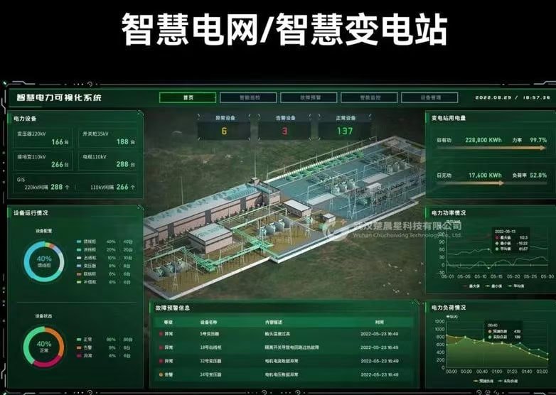
The rise of renewables, electric vehicles, and real-time energy markets has transformed how power flows through our grid—and modern transformers are central to this evolution. Today’s transformers are no longer passive voltage regulators; they are smart, responsive, grid-integrated devices that support intermittent renewable generation and dynamic demand profiles.
Modern transformers support renewable integration and smart grids by enabling voltage flexibility, bidirectional power flow, load balancing, real-time monitoring, and digital communication. They are designed to handle variable generation from solar and wind, coordinate with storage systems, and interact with grid control software to support demand-side management and fault localization.
Transformers have become smart grid nodes—equipped with sensors, digital relays, and network interfaces—that help orchestrate energy reliability and resilience in a decarbonized grid.
Traditional transformer designs are fully adequate for renewable and smart grid applications.False
Modern transformers incorporate advanced control, communication, and thermal features to accommodate fluctuating renewable sources and smart grid connectivity, which traditional designs cannot handle effectively.
🌞🌬️ Key Challenges of Renewable Power Integration
| Renewable Challenge | Transformer-Based Solution |
|---|---|
| Intermittent Output | Voltage regulation via OLTC or AVC transformers |
| Reverse Power Flow | Bidirectional load capability, dual-core windings |
| Harmonics from Inverters | Low-loss, harmonic-resistant magnetic design (K-rated) |
| Frequency Drift / Islanding | Real-time monitoring + grid-following protection |
| Low Fault Current Contribution | Enhanced sensitivity in digital relays |
🧠 Smart Grid Transformer Capabilities
| Feature | Benefit to Grid |
|---|---|
| Smart OLTC (On-Load Tap Changer) | Real-time voltage control in dynamic conditions |
| Digital Monitoring (IoT) | Health diagnostics, predictive failure alerts |
| Bidirectional Operation | Supports both import and export power flows |
| Edge Intelligence (µPMU) | Grid edge analytics for real-time decision-making |
| Thermal & Load Sensors | Dynamic loading with temperature-adaptive controls |
| Cyber-Secure Communication | Integrates with SCADA/DMS/EMS for smart grid compliance |
🔌 Application Roles of Modern Transformers in Smart Grids
| Role | Location | Example Use Case |
|---|---|---|
| Grid-Connected Solar Inverter XFMR | Solar farms | Handles reverse flow + daytime voltage swings |
| Wind Farm Step-Up XFMR | Wind turbine clusters | 0.69 kV to 33 kV/66 kV → transmission |
| Battery Energy Storage Interface | Microgrids | Bidirectional power and dynamic frequency |
| EV Charging Hub XFMR | Urban distribution | High-load variation, nighttime charging |
| Smart Distribution XFMR | City substations | Dynamic voltage control with AMI feedback |
📊 Functional Comparison: Traditional vs Modern Transformer
| Feature | Traditional XFMR | Smart/Modern XFMR |
|---|---|---|
| Voltage Regulation | Manual or fixed tap (DETC) | Automatic on-load tap (OLTC with sensors) |
| Direction of Power Flow | Unidirectional | Bidirectional |
| Digital Communication | None | SCADA, IEC 61850, Modbus enabled |
| Load Monitoring | Periodic manual | Continuous IoT-based |
| Harmonic Handling | Basic iron core | Low-flux density, K-rated design |
| Predictive Maintenance | Manual inspection | Sensor-driven diagnostics |
📘 Design Standards & Guidelines for Smart XFMRs
| Standard / Framework | Applicability |
|---|---|
| IEC 60076-22 | Power transformers with digital sensors |
| IEEE C57.104 | Monitoring and diagnostics of mineral oil insulation |
| IEC 61850 | Substation automation and communication protocols |
| IEEE 2030.5 / OpenADR | Smart grid interoperability (North America) |
| EU EcoDesign Tier 2 | Efficiency baseline for grid-connected transformers |
🌍 Real-World Example
A 132/33 kV transformer at a hybrid wind-solar site in India was upgraded with:
- Smart OLTC + real-time tap controller
- SCADA interface (IEC 61850)
- IoT temperature, oil level, and partial discharge sensors
- Bidirectional protection relays
Result: smoother grid voltage control, improved fault localization, and better load shedding coordination during cloud cover fluctuations.
Conclusion
Power transformers are indispensable in enabling a functional, reliable, and efficient power grid. From stepping up voltages for cross-country transmission to stepping them down for safe distribution, transformers ensure that energy flows with minimal loss and maximum safety. As grids become smarter and cleaner, power transformers continue to evolve with enhanced monitoring, digital control, and eco-friendly technologies—solidifying their importance in the future of energy infrastructure.
FAQ
Q1: What is the primary role of power transformers in the transmission network?
A1: Power transformers step up voltage from generation stations (e.g., 11–25kV) to high transmission voltages (e.g., 110–765kV), enabling:
Efficient long-distance electricity transmission
Reduced line losses due to lower current flow
Grid interconnectivity between power stations and regions
Without transformers, large-scale, economical power delivery would not be feasible.
Q2: How do transformers function in distribution networks?
A2: In distribution, power transformers step down voltage from transmission levels (e.g., 132kV, 66kV) to usable voltages (e.g., 11kV, 400V) for:
Commercial and industrial customers
Residential neighborhoods
Public infrastructure
They ensure safe, regulated voltage supply that matches local consumption needs.
Q3: What impact do transformers have on energy efficiency?
A3: Transformers:
Minimize I²R losses (current-related line losses) by operating at higher voltages
Provide voltage regulation through tap changers
Enable load balancing and fault isolation
These capabilities contribute to a more resilient and energy-efficient grid.
Q4: How do transformers support grid stability and scalability?
A4: Power transformers:
Maintain voltage levels and power quality
Allow connection of new substations or generation plants
Enable reactive power control for voltage regulation
They are critical for grid expansion, renewable energy integration, and smart grid functionality.
Q5: What would happen without power transformers in the grid?
A5: Without transformers:
Electricity couldn’t be transmitted over long distances cost-effectively
Local generators would need to serve small areas, increasing cost and emissions
Grid stability and voltage consistency would collapse
Power transformers are the backbone of modern electrical infrastructure.
References
"Role of Power Transformers in Transmission Networks" – https://www.electrical4u.com/power-transformers-transmission
"How Power Transformers Enable Grid Efficiency" – https://www.powermag.com/importance-of-transformers-in-grid
"IEEE: Power Transformer Grid Integration" – https://ieeexplore.ieee.org/document/8058632
"Smart Grid News: Transformers and Grid Evolution" – https://www.smartgridnews.com/power-transformer-grid
"Energy Central: Why Power Transformers Matter" – https://www.energycentral.com/c/ee/power-transformers-grid-role
"ScienceDirect: Transformer Impact on Grid Stability" – https://www.sciencedirect.com/grid-transformers-analysis