Oil-immersed transformers play a fundamental role in power transmission and distribution networks by providing both insulation and cooling through transformer oil. Their design variations cater to different operational requirements, installation environments, and voltage levels. Understanding the main types of oil-immersed transformers helps engineers, operators, and buyers select the most suitable model for efficient and reliable performance.
What Is an Oil-Immersed Transformer?
![]()
In modern electrical power systems, voltage must be transformed efficiently and safely across various stages—from generation to consumption. For medium to ultra-high voltage applications, oil-immersed transformers are the industry standard because they offer reliable insulation, superior cooling, and proven long-term durability. The defining feature of these transformers is their use of insulating oil, which submerges the internal components and acts as both a dielectric insulator and heat transfer medium.
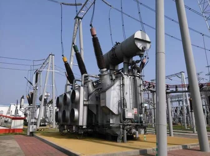
An oil-immersed transformer is a type of power transformer in which the magnetic core and windings are fully submerged in insulating oil. This oil serves dual functions: it electrically insulates the energized components and dissipates heat generated during operation by circulating through radiators. These transformers are widely used in high-voltage transmission networks, substations, industrial facilities, and renewable energy projects due to their reliability and thermal efficiency.
Oil-immersed transformers are engineered to handle voltages from 6.6 kV to 765 kV and capacities from 50 kVA to 1000+ MVA, making them ideal for grid-level applications.
Oil in transformers is used only for cooling and not for insulation.False
Insulating oil in oil-immersed transformers performs both critical functions: it cools the windings and insulates them from high voltage breakdown.
Key Components and Functions of an Oil-Immersed Transformer
| Component | Function |
|---|---|
| Magnetic Core | Directs magnetic flux to enable voltage transformation |
| Windings (HV/LV) | Carry electrical current; insulated and submerged in oil |
| Insulating Oil | Prevents electrical breakdown and removes heat |
| Main Tank | Holds the oil and active components in a sealed steel enclosure |
| Radiators / Coolers | Dissipate heat from the circulating oil to ambient air |
| Conservator Tank | Accommodates thermal oil expansion and contracts as temperatures change |
| Breather (Silica Gel) | Filters out moisture during air exchange in conservator system |
| Buchholz Relay | Detects internal faults by gas accumulation in the oil |
| Pressure Relief Valve | Releases internal overpressure in emergency conditions |
Main Types of Oil-Immersed Transformers
| Classification Criterion | Types |
|---|---|
| Cooling Method | ONAN, ONAF, OFAF, OFWF (Oil/Air/Natural/Forced combinations) |
| Oil Preservation | Conservator-type (with breather) vs Hermetically sealed (airtight) |
| Core Design | Core-type (standard) vs Shell-type (compact, high-strength) |
| Phase Configuration | Single-phase (modular) vs Three-phase (common in grid applications) |
Operating Voltage and Capacity Ranges
| Voltage Range (kV) | Power Capacity (MVA) | Typical Use Case |
|---|---|---|
| 6.6–33 kV | 50 kVA–5 MVA | Distribution, renewable energy |
| 66–132 kV | 2.5–80 MVA | Sub-transmission substations, industrial |
| 220–400 kV | 60–500 MVA | National grids, bulk power transmission |
| 765 kV+ | 500–1000+ MVA | Ultra high-voltage transmission corridors |
Key Advantages of Oil-Immersed Transformers
| Advantage | Explanation |
|---|---|
| High Voltage Capability | Handles up to 765 kV due to superior dielectric performance |
| Efficient Cooling | Oil convection supports long duty cycles and thermal balance |
| Long Service Life | Often exceeds 30–50 years with regular oil maintenance |
| Scalable Design | Supports custom power ratings and voltage classes |
| Monitoring Integration | Compatible with DGA, thermal, and moisture sensors |
Safety and Environmental Considerations
| Risk Factor | Control Measures |
|---|---|
| Fire Hazard (Mineral Oil) | Use fire barriers, mineral oil alternatives (ester), or detectors |
| Moisture Contamination | Maintain breather, seal integrity, periodic oil testing |
| Oil Leakage Risk | Use bund walls, leak alarms, maintenance inspection |
| Thermal Overload | Install RTDs, cooling fans, and overload relays |
Common Application Environments
| Sector | Typical Installations |
|---|---|
| Utilities | Transmission and distribution substations |
| Industrial Plants | Load centers, process control, motor drives |
| Renewables | Solar PV substations, wind turbine collection points |
| Transport | Railway traction substations, metro power feeds |
| Infrastructure | Airports, data centers, and critical facilities |
Real-World Deployment Example
- Application: 132/33 kV substation transformer
- Configuration: 40 MVA, ONAF-cooled, mineral oil filled
- Features: Buchholz relay, online DGA, conservator tank with smart breather
- Operation: 11+ years, <0.2% failure rate, 99.95% reliability
Result: Reliable voltage control, minimal maintenance, seamless integration into SCADA
How Are Oil-Immersed Transformers Classified by Cooling Method?
Cooling plays a crucial role in transformer efficiency, insulation lifespan, and thermal performance. Since electrical losses generate substantial heat inside oil-immersed transformers, engineers classify these systems based on how heat is transferred from the core and windings to the surrounding environment. The classification follows standardized cooling codes that describe both internal oil movement and external cooling medium circulation.
Oil-immersed transformers are classified by cooling method using standardized codes such as ONAN, ONAF, OFAF, and OFWF. These codes describe the behavior of the oil (internal coolant) and the cooling medium (air or water), indicating whether the flow is natural or forced. This classification helps determine the transformer’s thermal performance, cooling capacity, and load rating.
Choosing the correct cooling method ensures safe temperature rise, extended service life, and optimized load performance.
All oil-immersed transformers use the same cooling method regardless of size or rating.False
Oil-immersed transformers are classified into various cooling methods—ONAN, ONAF, OFAF, and OFWF—depending on power rating, size, and cooling requirements.
Cooling Code Format Explained
Each transformer cooling code consists of four letters, divided into two pairs:
| Code Segment | Meaning |
|---|---|
| 1st & 2nd | Internal fluid type and movement (O = oil; N = natural, F = forced) |
| 3rd & 4th | External medium and movement (A = air; W = water; N = natural, F = forced) |
For example:
- ONAN = Oil Natural Air Natural
- ONAF = Oil Natural Air Forced
- OFAF = Oil Forced Air Forced
- OFWF = Oil Forced Water Forced
Cooling Method Comparison Table
| Cooling Method | Internal Oil Flow | External Cooling Medium | Cooling Devices | Power Range | Application Scope |
|---|---|---|---|---|---|
| ONAN | Natural convection | Natural air | Radiators only | Up to 10–25 MVA | Distribution transformers, small substations |
| ONAF | Natural | Forced air (fans) | Radiators + fans | 25–60 MVA | Industrial, urban substations |
| OFAF | Forced oil (pumps) | Forced air (fans) | Pumps + fans | 60–200+ MVA | Large grid transformers, heavy load |
| OFWF | Forced oil | Forced water | Pumps + water coolers | 200–1000+ MVA | Power plants, offshore, nuclear, or confined environments |
Typical Performance Impact
| Cooling Method | Max Temperature Rise (°C) | Relative Cooling Efficiency | Load Rating Boost |
|---|---|---|---|
| ONAN | 55–65 | Baseline | 1× |
| ONAF | 45–55 | +30–40% | 1.4× |
| OFAF | 35–45 | +50–60% | 1.6–1.8× |
| OFWF | 30–40 | +70–90% | 2.0× or more |
Use Case Matching Guide
| Scenario | Best Cooling Method | Reason |
|---|---|---|
| Rural or standard utility use | ONAN | Low load, low noise, low complexity |
| Medium-load industrial use | ONAF | Occasional boost cooling during peak demand |
| Grid transformer with constant heavy load | OFAF | High power transfer, continuous cooling needed |
| Indoor or closed-loop cooling | OFWF | No air ventilation allowed; heat must go to water |
ONAN/ONAF dual-rated designs are common to increase rating flexibility.
Equipment and Components by Method
| Method | Cooling Equipment Used |
|---|---|
| ONAN | Radiators, expansion tank (passive airflow) |
| ONAF | Radiators, thermostatically controlled axial fans |
| OFAF | Oil pumps, fans, radiator banks, directional valves |
| OFWF | Oil pumps, water-to-oil heat exchangers, filtration units |
Real-World Case: 132/33 kV ONAF Transformer in Industrial Substation
- Rating: 40 MVA ONAN / 60 MVA ONAF
- Cooling: Fans activate above 60°C winding temperature
- Sensors: RTDs, oil flow monitors, load-controlled cooling logic
- Outcome: Stable under cyclic loading, 99.98% uptime over 9 years
Optimized cooling ensures thermal stability and insulation longevity.
What Are Sealed-Type and Conservator-Type Transformers?
Oil-immersed transformers require internal oil to maintain dielectric strength and cool the windings. However, when the transformer heats up, the oil expands and contracts—posing challenges for pressure control and moisture protection. To manage this, engineers have developed two main structural designs: the sealed-type and the conservator-type oil-immersed transformer. Each has a unique approach to controlling oil expansion and isolating the insulating fluid from the environment.
Sealed-type transformers are completely enclosed, using a pressurized or flexible tank system to accommodate oil expansion without external air contact. Conservator-type transformers use a dedicated oil expansion tank (conservator) equipped with a breather system to handle oil volume changes and reduce oxidation. The choice between them depends on voltage rating, maintenance strategy, and environmental conditions.
Understanding their differences is critical for transformer specification and lifecycle management.
All oil-immersed transformers use a conservator tank.False
Sealed-type oil-immersed transformers do not use a conservator tank. They manage oil expansion through a pressurized sealed enclosure or flexible diaphragm.
Structural Comparison
| Feature | Sealed-Type Transformer | Conservator-Type Transformer |
|---|---|---|
| Oil Expansion Handling | Tank flexes or pressurizes internally | Conservator tank handles expansion |
| Air Contact | None (sealed or nitrogen cushion) | Air exchange via silica gel breather |
| Moisture Ingress Risk | Very low (fully sealed) | Moderate (if breather or bladder fails) |
| Oil Aging Rate | Slower (no air exposure) | Faster (due to oxidation over time) |
| Volume Capacity | Small to medium | Medium to very large |
| Common Voltage Range | Up to 36 kV | 11–765 kV |
| Maintenance | Minimal | Requires breather and oil level checks |
| Applications | Urban networks, renewable inverters, indoor | Substations, grids, heavy industry |
Key Components in Each Design
| Component | Sealed-Type | Conservator-Type |
|---|---|---|
| Main Tank | Fully welded and sealed | Connected to conservator via oil pipe |
| Oil Expansion System | Nitrogen cushion, bellows, diaphragm | Conservator with free surface or bladder |
| Breather System | Not required | Silica gel breather required |
| Pressure Relief Device | Required for safety | Required for pressure management |
Visual Functionality Overview
| Aspect | Sealed-Type | Conservator-Type |
|---|---|---|
| Oil Isolation | Excellent – no external exposure | Depends on breather integrity |
| Thermal Stress Handling | Limited (small tanks) | Excellent (large expansion volume) |
| Oil Testing Access | Requires opening or valve sampling | Simple dipstick or valve at conservator |
Typical Use Case Profiles
| Sector | Preferred Type | Justification |
|---|---|---|
| Urban Indoor Installations | Sealed-Type | Space-saving, no maintenance access needed |
| Rooftop Solar Projects | Sealed-Type | Compact, zero oil exposure risk |
| Utility Substations | Conservator-Type | High capacity, scalable, field-maintainable |
| Industrial Plants | Conservator-Type | Suitable for long duty cycles and oil analysis |
Performance and Monitoring
| Performance Factor | Sealed-Type | Conservator-Type |
|---|---|---|
| Dielectric Stability | Consistent (sealed system) | Requires oil testing over time |
| Oil Life | Extended | Degrades over years of breathing |
| Sensor Compatibility | Limited | Supports full DGA and online systems |
| Installation Cost | Lower for small units | Higher due to tank and accessories |
Real-World Example – Compact Wind Farm Application
- Installation: 2.5 MVA, 33/0.69 kV sealed-type transformer at wind turbine base
- Reason: Indoor nacelle mounting, no fire suppression system needed
- Features: Bellows-type expansion chamber, thermally isolated tank
- Outcome: 10+ years of operation with zero maintenance and no oil degradation
What Are the Core Construction Types: Core-Type vs. Shell-Type?
When designing an oil-immersed transformer, one of the foundational decisions is the configuration of the magnetic core. This directly influences the transformer's magnetic flux flow, mechanical strength, size, cost, and cooling efficiency. There are two principal magnetic core construction types: the core-type and the shell-type. Each has unique characteristics that make it more suitable for specific power ratings, operational demands, and mechanical stresses.
Core-type transformers feature a magnetic core that is surrounded by the windings, with the flux primarily flowing through two vertical limbs. Shell-type transformers have the windings enclosed within a central magnetic path, with the flux circulating through three limbs. Core-type designs are preferred for high-voltage and large power applications due to their efficient cooling and lower core loss, while shell-type designs are chosen for applications with high short-circuit stress and compact installation needs.
Selecting the appropriate core structure is essential for optimizing performance, durability, and cost.
Shell-type transformers are typically used for extra-high-voltage transmission systems.False
Shell-type transformers are generally used in low- to medium-voltage or special-purpose applications. Core-type designs dominate extra-high-voltage transmission due to better cooling and lower magnetic losses.
Magnetic Flux and Structural Overview
| Parameter | Core-Type Construction | Shell-Type Construction |
|---|---|---|
| Magnetic Core Shape | Two vertical limbs with top and bottom yokes | Central limb flanked by two return limbs |
| Flux Path | Flux flows through two vertical limbs | Flux splits and returns through side limbs |
| Winding Arrangement | Surrounds each core limb | Enclosed within the core |
| Core Material Use | Less material, longer limbs | More material, shorter limbs |
| Cooling Efficiency | Excellent (easier oil flow) | Moderate (enclosed structure) |
Structural Comparison Table
| Characteristic | Core-Type | Shell-Type |
|---|---|---|
| Manufacturing Complexity | Simpler, cost-effective | More complex, higher manufacturing cost |
| Mechanical Strength | Moderate (external support needed) | High (stronger structure) |
| Short-Circuit Withstand | Moderate | Excellent (internal bracing structure) |
| Space Requirement | Taller, narrower | More compact footprint |
| Winding Protection | Exposed to short-circuit forces | Enclosed, better support against stress |
Application Suitability
| Use Case | Preferred Type | Reason |
|---|---|---|
| High-Voltage Power Transmission | Core-Type | Better cooling, lower core loss, scalable to 765 kV+ |
| Furnace Transformers | Shell-Type | High-current, compact, robust under stress |
| Mobile Substations | Shell-Type | Compact, low profile for transportable units |
| Large Distribution Transformers | Core-Type | Economical, field-tested scalability |
| Traction and Rail Substations | Shell-Type | Resilient to dynamic load and mechanical vibration |
Design Performance Comparison
| Performance Aspect | Core-Type | Shell-Type |
|---|---|---|
| No-Load Losses | Lower due to flux uniformity | Slightly higher due to split flux path |
| Thermal Performance | Better oil circulation | Moderate, oil flows around compact windings |
| Electrical Efficiency | High | Slightly lower at large ratings |
| Serviceability | Easier coil removal and repair | Harder to access windings |
| Custom Design Flexibility | More standardised | Higher customization potential |
Typical Voltage and Rating Applications
| Voltage Rating | Power Rating (Typical) | Preferred Type |
|---|---|---|
| 11–33 kV | ≤5 MVA | Shell-Type |
| 33–220 kV | 5–80 MVA | Core-Type |
| 220–765 kV | 60–1000+ MVA | Core-Type |
| <11 kV (Compact) | ≤2.5 MVA | Shell-Type |
Real-World Example: Industrial Shell-Type Transformer
- Application: Electric arc furnace
- Rating: 5 MVA, 33/0.69 kV
- Design: Shell-type, forced oil-air cooling (OFAF)
- Features: High short-circuit withstand, compact tank, low leakage reactance
- Outcome: Sustained performance under cyclic thermal/mechanical stress
Ideal for heavy-duty environments with frequent load surges
How Are Oil-Immersed Transformers Categorized by Application?
Oil-immersed transformers are indispensable across the electrical value chain—from high-voltage power transmission to localized distribution, industrial loads, renewable energy generation, and critical infrastructure. To ensure optimal performance and economic viability, these transformers are categorized by application, each type being engineered to match the voltage level, loading pattern, environmental condition, and regulatory needs of its specific domain.
Oil-immersed transformers are categorized by application into transmission transformers, distribution transformers, industrial transformers, renewable energy transformers, and infrastructure-specific transformers. Each category addresses distinct voltage classes, power ranges, cooling methods, and durability requirements based on where and how the transformer operates in the power system.
Choosing the right category ensures efficiency, system compatibility, and asset longevity.
All oil-immersed transformers serve the same purpose regardless of application.False
Oil-immersed transformers are application-specific; their design, cooling, insulation, and ratings are customized for transmission, distribution, industrial, renewable, or infrastructure roles.
Application-Based Categories and Characteristics
| Category | Voltage Range | Power Range | Key Features | Typical Settings |
|---|---|---|---|---|
| Transmission Transformers | 132–765 kV | 60–1000+ MVA | Core-type, ONAF/OFAF/OFWF cooling, online monitoring | HV substations, national grids |
| Distribution Transformers | 6.6–33 kV | 50 kVA–5 MVA | ONAN cooling, sealed or conservator type | Residential, commercial feeders |
| Industrial Transformers | 11–132 kV | 2.5–100 MVA | High short-circuit withstand, robust insulation | Steel plants, mines, refineries |
| Renewable Transformers | 0.69–220 kV | 0.5–60 MVA | Eco-friendly oils, compact design, grid-tie compatibility | Wind farms, solar PV stations |
| Infrastructure Transformers | 11–66 kV | 1–25 MVA | Fire-safe options, smart diagnostics | Airports, metros, data centers, campuses |
1. Transmission Transformers
- Handle ultra-high voltages and bulk power movement
- Must withstand high thermal and mechanical stress
- Designed with online DGA, forced oil cooling, and custom insulation coordination
Example: 400/220 kV, 315 MVA OFAF transformer with nitrogen-sealed conservator
2. Distribution Transformers
- Installed on poles or pads near the load
- Typically ONAN-cooled, compact, and often sealed for maintenance-free operation
- Supports residential and commercial low-voltage networks
Example: 33/0.4 kV, 160 kVA sealed-type for suburban neighborhood
3. Industrial Transformers
- Designed for continuous, heavy load with frequent switching
- High short-circuit withstand, low leakage reactance, and custom tap changers
- Often shell-type for mechanical robustness
Example: 66/6.6 kV, 20 MVA for electric arc furnace substation
4. Renewable Energy Transformers
- Serve grid connection and inverter step-up purposes
- Designed for high harmonics, compact layout, and eco-safe operation
- Often use natural ester oil and sealed tanks
Example: 0.69/33 kV, 2.5 MVA transformer inside wind turbine nacelle
5. Infrastructure Transformers
- Used in public or sensitive installations like hospitals, metros, and airports
- Fire resistance, noise control, and remote monitoring prioritized
- May be dry-type in ultra-sensitive zones but oil-filled for higher loads
Example: 33/0.4 kV, 5 MVA ONAF transformer for metro rail power supply
Application vs Design Correlation Table
| Design Attribute | Transmission | Distribution | Industrial | Renewable | Infrastructure |
|---|---|---|---|---|---|
| Voltage Class | Very High | Low-Medium | Medium-High | Medium | Low-Medium |
| Cooling Type | OFAF/OFWF | ONAN | ONAN/ONAF | ONAN/ONAF | ONAN/ONAF |
| Monitoring Complexity | Advanced | Basic | Moderate | Smart-ready | Smart-enabled |
| Oil System | Conservator | Sealed/Cons | Conservator | Sealed | Sealed/Cons |
| Core Type | Core-Type | Core-Type | Shell/Core | Core/Shell | Core-Type |
Real-World Case Study: Multi-Type Deployment
- Project: 100 MW wind farm with 220 kV grid connection
- Collector transformers: 2.5 MVA, 33/0.69 kV sealed eco-oil units
- Substation transformer: 60 MVA, 220/33 kV conservator-type with OFAF cooling
- Purpose: Link distributed inverters to national grid
Result: Optimized reliability, eco-compliance, and thermal capacity under variable renewable load
What Environmental or Performance Factors Affect Transformer Type Selection?
Selecting the right type of transformer—oil-filled or dry-type—is not only a technical consideration but also a response to site-specific environmental and performance conditions. Transformers must operate reliably in a variety of climates, altitudes, enclosures, and load scenarios. These conditions significantly affect insulation life, cooling performance, safety compliance, and the overall economics of transformer ownership.
Environmental and performance factors that influence transformer type selection include ambient temperature, installation altitude, fire safety requirements, space constraints, moisture or contamination levels, load profile (continuous or cyclic), noise limitations, and maintenance accessibility. These variables determine whether an oil-filled or dry-type transformer is better suited to the site.
The correct choice minimizes operational risk, ensures regulatory compliance, and optimizes performance over the transformer’s lifecycle.
Transformer selection is purely based on voltage and capacity.False
Transformer selection must also consider environmental conditions, fire safety, cooling requirements, maintenance access, and spatial constraints—not just voltage or capacity.
Environmental Factors Affecting Transformer Choice
| Environmental Condition | Influence on Transformer Selection |
|---|---|
| Ambient Temperature | High temperatures may require forced cooling or derating |
| Altitude (>1000 m) | Reduced air density impairs cooling; dry-types may overheat |
| Humidity and Moisture | Sealed or cast resin preferred to avoid insulation degradation |
| Contaminated Air (dust, salt, corrosive gases) | Dry-type in IP enclosures or sealed oil units recommended |
| Seismic Activity Zones | Shell-type or dry-type units with seismic certification required |
| Outdoor Exposure | Oil-filled with IP54/IP65 rating and UV/storm protection needed |
Performance Factors That Influence Type Selection
| Performance Requirement | Preferred Transformer Type | Reason |
|---|---|---|
| Continuous Heavy Load | Oil-Filled | Superior thermal inertia and cooling capacity |
| High Overload Tolerance | Oil-Filled | Thermal reserve due to oil immersion |
| Short-Circuit Withstand | Shell-Type or Oil-Filled | Greater mechanical resilience |
| Fire Safety | Dry-Type or Ester Oil | Flame-retardant, safer for public or enclosed spaces |
| Noise Limitation | Dry-Type or Low-noise Oil-Filled | Quieter options available with fan control |
| Limited Maintenance Access | Dry-Type or Hermetically Sealed | No breather, oil testing, or conservator required |
Space and Access Constraints
| Constraint | Transformer Implication |
|---|---|
| Confined Indoor Room | Dry-type preferred for footprint and ventilation |
| Rooftop Solar Install | Hermetically sealed for low profile and fire safety |
| Vault or Tunnel Access | Dry-type or gas-insulated preferred |
| Long Cable Runs | May require oil-filled to support higher reactance |
Site-Specific Case Matching Table
| Site Type | Environmental & Performance Needs | Recommended Transformer Type |
|---|---|---|
| Data Center | Low noise, fire-safe, compact, minimal maintenance | Dry-Type |
| Wind Turbine Tower | Vibration, salt air, confined space | Cast Resin or Sealed Oil-Type |
| Urban Substation | High capacity, outdoor reliability, noise control | Oil-Filled ONAF or OFAF |
| Metro Rail Station | Underground, fire-critical, dusty | Dry-Type, IP44/IP55 enclosure |
| Tropical Solar Farm | High heat, humidity, minimal service access | Sealed Oil-Filled with ester oil |
| Offshore Platform | Corrosive air, explosion-proof needed | Dry-Type or Gas-Insulated |
Key Design Considerations by Environmental Condition
| Design Factor | Critical for… | Recommended Mitigation |
|---|---|---|
| Oil Leakage Risk | Protected water bodies, indoor sites | Use ester oil or switch to dry-type |
| Heat Dissipation | High-load or high ambient areas | Use ONAF/OFAF or derate transformer |
| Corrosion Protection | Coastal or chemical zones | Stainless steel tank, IP65 enclosures |
| Cooling Space | Space-constrained areas | Compact dry-type or OFWF design |
| Insulation Aging | Moist/humid climates | Hermetically sealed or solid resin |
Real-World Example – Transformer Selection in Coastal Substation
- Location: Coastal industrial plant
- Condition: High humidity, salt air, limited maintenance staff
- Requirements: 11 kV, 3 MVA load, fire resistance, zero oil leakage
- Decision: Sealed-type transformer with natural ester oil, IP55 rating
- Features: Corrosion-resistant paint, pressure relief, smart breather
Outcome: 5+ years operation with no oil change, no fire risk, and stable insulation performance
Conclusion
Oil-immersed transformers come in various types to meet the diverse needs of modern power systems. From small sealed distribution transformers to large forced-oil-cooled power transformers, each type is designed for specific technical and environmental demands. By understanding their classifications—whether by cooling method, structure, or application—utilities and industries can ensure safe, efficient, and long-term transformer operation.
FAQ
Q1: What are the main classifications of oil-immersed transformers?
A1: Oil-immersed transformers are primarily classified by:
Function: Distribution, power, or special-purpose
Phase: Single-phase or three-phase
Cooling method: ONAN, ONAF, OFAF, etc.
Core design: Core-type or shell-type
Each type is tailored for specific voltage levels, load demands, and installation environments.
Q2: What is an oil-immersed distribution transformer?
A2: Distribution transformers:
Typically ≤2.5 MVA
Step down medium voltage (e.g., 11 kV) to usable voltage (e.g., 400V)
Commonly used in residential, commercial, and light industrial areas
Often sealed with a conservator tank or hermetically sealed to manage oil expansion
Q3: What is an oil-immersed power transformer?
A3: Power transformers:
Range from 5 MVA to 1000+ MVA
Step up or step down voltage at generation and transmission levels
Used in power plants, substations, and heavy industrial facilities
Built for continuous duty, high efficiency, and robust cooling systems
Q4: What are autotransformers in oil-immersed form?
A4: Oil-immersed autotransformers:
Use a single winding for both primary and secondary circuits
Are more compact and cost-effective than conventional transformers
Common in interconnecting different voltage grids or HVAC applications
Handle large power transfers with reduced copper and core loss
Q5: What are the key cooling classifications of oil-immersed transformers?
A5: According to IEC/IEEE cooling standards:
ONAN (Oil Natural Air Natural) – Natural convection in oil and air; used for low to medium power units
ONAF (Oil Natural Air Forced) – Fans force air across radiators for better cooling
OFAF (Oil Forced Air Forced) – Pumps and fans used for high power transformers
OFWF (Oil Forced Water Forced) – Requires external water cooling; used in very high-power installations
Cooling method selection is based on load capacity, location, and thermal performance.
References
"Oil-Immersed Transformer Types and Uses" – https://www.electrical4u.com/types-of-oil-immersed-transformers
"IEEE C57 Transformer Classification Standards" – https://ieeexplore.ieee.org/document/8965623
"ScienceDirect: Comparative Analysis of Oil-Immersed Transformers" – https://www.sciencedirect.com/oil-transformer-comparison
"Doble Engineering: Transformer Design and Testing" – https://www.doble.com/oil-transformer-engineering
"NREL: Oil Transformer Performance in Grid Systems" – https://www.nrel.gov/docs/oil-transformers-grid-performance.pdf