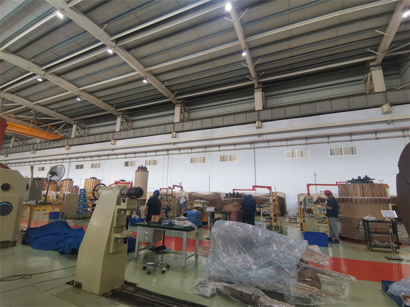
Proper installation and commissioning of oil-immersed transformers are critical to ensuring long-term reliability and efficient operation. Mistakes during these early stages can lead to performance issues, electrical faults, or even catastrophic failures, resulting in costly downtime and repairs. Many operators overlook key factors such as site preparation, oil handling, and system testing, which can significantly impact transformer performance.
This article provides a step-by-step guide to oil-immersed transformer installation and commissioning, highlighting best practices to prevent common issues and ensure a smooth, trouble-free startup.
What Are the Key Steps in Preparing for Oil-Immersed Transformer Installation?

Oil-immersed transformers are crucial for power distribution, ensuring efficient voltage conversion with effective insulation and cooling. However, improper installation can lead to electrical failures, oil leaks, overheating, or reduced efficiency, resulting in expensive repairs and downtime. To guarantee a safe and efficient installation, following a structured pre-installation checklist is essential.
The key steps in preparing for oil-immersed transformer installation include site selection, foundation preparation, oil quality inspection, transportation planning, electrical connections, and safety checks. Proper installation ensures transformer efficiency, reliability, and longevity while minimizing operational risks.
This guide outlines best practices, technical considerations, and safety protocols to ensure a smooth transformer installation process.
Oil-immersed transformers can be installed anywhere without site preparation.False
Proper site selection and foundation preparation are critical for transformer stability, cooling efficiency, and safety.
1. Site Selection and Environmental Considerations
Before installation, choosing an appropriate site is crucial to ensure long-term performance and safety. Key factors to consider include:
- Load Accessibility: Ensure proximity to power loads to minimize transmission losses.
- Cooling Efficiency: Select a well-ventilated area to enhance heat dissipation.
- Flood and Weather Protection: Avoid flood-prone or high-humidity locations to prevent insulation degradation.
- Ground Stability: The site must support the transformer's weight without settling.
Site Preparation Checklist
| Factor | Requirement | Purpose |
|---|---|---|
| Elevation | Install on raised platforms if in a flood zone | Prevents water damage |
| Ventilation | Maintain clearance for airflow | Enhances cooling |
| Grounding System | Properly designed earthing | Ensures safety and voltage stability |
| Drainage System | Ensure proper drainage | Prevents oil contamination and leaks |
2. Transformer Foundation and Mounting Preparation
The foundation must be strong enough to support the transformer's weight and prevent vibrations that can damage components.
A. Foundation Requirements
- Concrete Pad Strength: Must support full transformer weight, including oil.
- Vibration Isolation: Use rubber pads or dampers for seismic zones.
- Anchor Bolts: Secure the transformer to prevent movement.
- Clearance Guidelines: Maintain space for cooling, maintenance, and safety access.
B. Foundation Load Calculations
| Transformer Rating (MVA) | Estimated Weight (kg) | Recommended Foundation Thickness (cm) |
|---|---|---|
| 1 - 5 MVA | 2,000 - 5,000 | 30 - 40 |
| 5 - 10 MVA | 5,000 - 10,000 | 40 - 50 |
| 10 - 25 MVA | 10,000 - 25,000 | 50 - 60 |
Failure to prepare a strong foundation may result in mechanical stress, misalignment, and instability.
3. Transportation and Handling Precautions
Oil-immersed transformers are heavy and fragile, requiring specialized transportation planning.
A. Transport Considerations
- Ensure Road Access: Check route conditions and bridge load limits.
- Use Proper Lifting Equipment: Cranes must have sufficient load capacity.
- Transport Without Oil: Prevents sloshing damage during movement.
- Shock and Tilt Monitoring: Use sensors to detect excessive vibrations.
B. Safe Unloading and Positioning
| Step | Action | Safety Precaution |
|---|---|---|
| Lifting | Use slings/chains at designated lifting points | Prevent transformer tilting |
| Positioning | Lower onto the foundation gently | Avoid mechanical shocks |
| Alignment | Check for correct orientation | Ensure cooling efficiency |
Transporting transformers incorrectly can lead to core misalignment and winding displacement, affecting performance.
4. Oil Inspection and Treatment Before Installation
Transformer oil provides insulation and cooling but must be tested before use.
A. Key Oil Quality Tests
| Test Name | Purpose | Acceptable Value |
|---|---|---|
| Dielectric Strength Test | Ensures insulation capability | >30 kV |
| Moisture Content Test | Prevents electrical breakdown | <10 ppm |
| Acid Number Test | Checks oil aging and contamination | <0.05 mg KOH/g |
B. Oil Filtration and Degassing
New oil must be filtered and degassed before filling to remove moisture and dissolved gases.
C. Oil Filling Procedure
- Check for Leaks: Inspect gaskets and seals.
- Use a Vacuum Filling Method: Reduces moisture contamination.
- Monitor Oil Temperature: Keep within ambient temperature limits.
Poor oil quality can reduce dielectric strength, increasing failure risks.
5. Electrical Connection and Grounding
Correct wiring ensures safe operation and voltage regulation.
A. Transformer Wiring Configuration
| Connection Type | Application | Advantages |
|---|---|---|
| Delta-Delta (Δ-Δ) | Industrial power systems | Handles unbalanced loads |
| Star-Star (Y-Y) | High-voltage transmission | Neutral availability |
| Delta-Star (Δ-Y) | Distribution transformers | Stepping down high voltage |
B. Grounding and Protection Measures
- Connect the neutral point to a proper earthing system.
- Use surge arresters to protect from voltage spikes.
- Install fuses and circuit breakers for overload protection.
6. Pre-Commissioning Tests and Safety Checks
Before powering up, transformers must undergo rigorous testing to ensure safety and operational readiness.
A. Electrical Tests Before Energization
| Test Name | Purpose | Required Limit |
|---|---|---|
| Insulation Resistance Test | Checks insulation health | >100 MΩ |
| Turns Ratio Test | Confirms correct voltage ratios | ±0.5% tolerance |
| Short-Circuit Test | Measures impedance | Within design specs |
B. Thermal Monitoring Before Start-Up
- Check winding and oil temperature.
- Ensure cooling fans or radiators function properly.
7. Final Energization and Performance Monitoring
Once all tests are complete, the transformer is gradually energized.
A. Initial Start-Up Checklist
- Confirm all electrical connections.
- Verify oil levels and temperatures.
- Gradually apply voltage and monitor load.
B. Post-Installation Monitoring
| Parameter | Normal Range | Frequency of Monitoring |
|---|---|---|
| Oil Temperature | 40-60°C | Daily |
| Winding Temperature | <90°C | Daily |
| Load Current | Within design limits | Continuous |
If abnormalities appear, shutdown and re-evaluate before full operation.
How Should Site Selection and Foundation Preparation Be Handled for Oil-Immersed Transformers?
Proper site selection and foundation preparation are critical to ensuring the long-term reliability, efficiency, and safety of an oil-immersed transformer. If these steps are not handled correctly, issues like uneven weight distribution, overheating, moisture ingress, and mechanical vibrations can lead to transformer failure and costly repairs.
Site selection and foundation preparation for oil-immersed transformers require careful evaluation of environmental conditions, structural stability, accessibility, and safety measures. The site must provide adequate ventilation, protection from moisture, and a solid foundation capable of supporting the transformer’s weight while minimizing vibrations. A well-prepared site ensures optimal performance, longevity, and reduced maintenance costs.
This guide provides detailed steps for site selection criteria, foundation design requirements, load distribution calculations, and best practices for installing a transformer securely and efficiently.
An oil-immersed transformer can be installed on any flat surface without preparation.False
Proper site selection and foundation design are essential to support the transformer's weight, prevent vibrations, and ensure efficient cooling.
1. Key Considerations for Transformer Site Selection
Choosing the right installation site directly impacts the transformer's cooling efficiency, safety, and maintenance requirements.
A. Environmental Factors
- Avoid flood-prone areas: Install on elevated platforms in high-risk flood zones.
- Ensure proper ventilation: Transformers generate heat, so avoid confined spaces.
- Prevent exposure to direct sunlight: Overheating can reduce oil efficiency and insulation lifespan.
- Minimize dust and contamination: Particulate matter can degrade insulation over time.
B. Site Accessibility and Safety
- Proximity to Load Centers: Minimizes power losses in transmission lines.
- Ease of Maintenance: Ensure sufficient space for oil testing, inspections, and repairs.
- Safe Distance from Other Equipment: Prevents overheating and fire hazards.
C. Clearances and Safety Distances
The following table outlines the minimum recommended clearances around a transformer:
| Component | Minimum Clearance (m) | Purpose |
|---|---|---|
| Wall or Fence | 1.5 - 2.0 | Ensure airflow and accessibility |
| Adjacent Equipment | 2.0 - 3.0 | Prevent overheating and interference |
| Overhead Conductors | 4.5+ | Avoid electrical discharge risk |
| Personnel Access Area | 1.2 - 1.5 | Provide safe working space |
Installing barriers and warning signs around the transformer improves operational safety.
2. Foundation Design and Load Distribution
A transformer weighs several tons, requiring a well-designed foundation to prevent structural failures.
A. Foundation Requirements
- Load Capacity: The foundation must support the full weight of the transformer, including oil.
- Vibration Isolation: Use rubber pads or damping materials to reduce mechanical stress.
- Leveling and Stability: Ensure a perfectly level surface to prevent misalignment.
- Thermal Expansion Allowance: Provide expansion joints to accommodate temperature changes.
B. Transformer Weight and Foundation Thickness
The table below provides guidelines for foundation thickness based on transformer size:
| Transformer Rating (MVA) | Estimated Weight (kg) | Recommended Foundation Thickness (cm) |
|---|---|---|
| 1 - 5 MVA | 2,000 - 5,000 | 30 - 40 |
| 5 - 10 MVA | 5,000 - 10,000 | 40 - 50 |
| 10 - 25 MVA | 10,000 - 25,000 | 50 - 60 |
C. Concrete Pad Design
- Use reinforced concrete (M30 or higher) for stability.
- Foundation width should be at least 1.5 times the transformer base size.
- Install anchor bolts to secure the transformer in place.
3. Drainage and Oil Containment Systems
Transformer oil leaks can pose environmental hazards. A proper drainage system ensures safety and compliance with regulations.
A. Oil Spill Containment Pit
- Construct an oil sump below the foundation to collect leaks.
- Use gravel or crushed stone layers for oil absorption.
- Install an oil-water separator to prevent groundwater contamination.
B. Drainage Design Considerations
| Drainage Feature | Purpose |
|---|---|
| Slope (2-5%) | Directs water away from the foundation |
| Oil Collection Pit | Prevents environmental contamination |
| Waterproof Sealing | Protects the foundation from oil penetration |
Regularly inspect and clean drainage systems to ensure proper operation.
4. Transformer Placement and Vibration Control
A. Positioning the Transformer on the Foundation
- Use a crane or hydraulic lifting system for precise placement.
- Align transformer feet with pre-installed anchor bolts.
- Verify horizontal and vertical leveling to prevent stress on bushings and connections.
B. Vibration Damping Methods
Excessive vibrations can damage windings, insulation, and core laminations. To reduce vibrations:
- Install rubber vibration pads between the transformer base and foundation.
- Use spring-loaded damping systems in seismic-prone areas.
- Check for loose mounting bolts and tighten them securely.
5. Final Pre-Installation Checklist
Before moving forward with installation, complete the following:
| Checklist Item | Status |
|---|---|
| Site clearances meet safety requirements | ✅ / ❌ |
| Foundation is level and meets load requirements | ✅ / ❌ |
| Drainage and oil containment systems are installed | ✅ / ❌ |
| Anchor bolts and vibration dampers are secured | ✅ / ❌ |
| Protective barriers and signage are in place | ✅ / ❌ |
What Are the Best Practices for Transporting and Handling an Oil-Immersed Transformer?
Transporting and handling oil-immersed transformers is a high-risk operation that requires careful planning, specialized equipment, and strict safety protocols. Transformers are heavy, delicate, and filled with insulating oil, making them susceptible to mechanical stress, oil leakage, and core misalignment if not handled properly. Poor transportation or mishandling can lead to insulation failure, electrical faults, and costly repairs.
The best practices for transporting and handling an oil-immersed transformer include route planning, secure loading, shock and tilt monitoring, oil-level management, and careful unloading procedures. Using proper lifting techniques and vibration control ensures transformer integrity and prevents mechanical damage.
This guide outlines step-by-step best practices to ensure the safe and damage-free transportation of oil-immersed transformers.
Oil-immersed transformers can be transported like regular industrial equipment.False
Oil-immersed transformers require specialized transportation due to their weight, delicate components, and risk of oil leakage.
1. Pre-Transport Preparations and Planning
Before transporting an oil-immersed transformer, careful planning is essential to minimize risks and avoid accidents.
A. Route Planning and Site Preparation
- Survey the transport route for road conditions, weight restrictions, and bridge capacities.
- Check for overhead clearances (power lines, tunnels, bridges) to prevent contact.
- Plan for escorts and permits if required for oversized loads.
- Ensure the destination site is ready with a proper foundation and unloading equipment.
B. Transformer Preparation Before Transport
- Drain excess oil if required, leaving a safe level for insulation.
- Secure all removable components (bushings, radiators, fans) separately.
- Protect insulation and bushings with wooden or padded covers.
- Install shock and tilt sensors to monitor movement.
Pre-Transport Checklist
| Task | Status |
|---|---|
| Route survey completed | ✅ / ❌ |
| Transformer weight and dimensions verified | ✅ / ❌ |
| Oil level adjusted for transport | ✅ / ❌ |
| Shock and tilt sensors installed | ✅ / ❌ |
| Lifting and securing points verified | ✅ / ❌ |
2. Safe Loading and Securing the Transformer
Incorrect loading can cause mechanical stress, leading to winding displacement, core misalignment, or tank deformation.
A. Proper Lifting Techniques
- Use only designated lifting points marked on the transformer.
- Cranes or hydraulic jacks should match the weight capacity of the transformer.
- Balance the weight evenly to avoid tilting.
- Use spreader beams to distribute lifting force evenly.
B. Secure Fastening on the Transport Vehicle
- Use heavy-duty tie-downs to prevent shifting.
- Wooden blocks or rubber pads should be placed under the transformer to absorb vibrations.
- Install shock absorbers for long-distance transport.
Best Practices for Securing Transformers
| Factor | Best Practice |
|---|---|
| Lifting | Use lifting eyes or brackets, avoid side pulls |
| Securing | Fasten with multiple straps, check tightness |
| Padding | Place rubber mats under the base to prevent vibration |
| Shock Protection | Use hydraulic dampers for impact absorption |
3. Monitoring Transformer Condition During Transport
Transporting a large, delicate transformer requires continuous monitoring to detect any excessive shock, tilting, or leaks.
A. Key Monitoring Tools
| Monitoring Device | Purpose | Recommended Threshold |
|---|---|---|
| Shock Recorders | Detect impact force | <2 g |
| Tilt Sensors | Monitor inclinations | <10° |
| Temperature Sensors | Track temperature changes | <50°C |
| Leak Detection Sensors | Identify oil leaks | Zero leaks tolerated |
B. Driver and Escort Responsibilities
- Regularly inspect the transformer at scheduled stops.
- Check for oil leaks, unusual noises, or loose fastenings.
- Ensure the vehicle is moving at safe speeds to minimize vibrations.
4. Safe Unloading and Positioning at the Site
A. Preparing the Transformer for Unloading
- Confirm the foundation is ready to support the transformer weight.
- Clear the area of obstacles to allow crane access.
- Inspect the transformer for transport damage before unloading.
B. Unloading Best Practices
| Step | Action | Precaution |
|---|---|---|
| Lifting | Use only designated lifting points | Avoid sudden movements |
| Lowering | Place on rubber pads or dampers | Prevent vibration impact |
| Alignment | Use laser leveling if needed | Ensure stable placement |
Avoid dropping or tilting the transformer excessively during unloading.
5. Post-Transport Inspections and Commissioning
Before energizing the transformer, a thorough inspection is required to confirm its integrity.
A. Visual and Structural Inspection
- Check for any oil leaks from tanks or seals.
- Inspect bushings and terminals for cracks or damage.
- Verify all connections and components are intact.
B. Electrical and Oil Testing Before Operation
| Test Name | Purpose | Acceptable Value |
|---|---|---|
| Insulation Resistance Test | Ensure insulation health | >100 MΩ |
| Dielectric Oil Test | Verify oil quality | >30 kV |
| Core and Winding Check | Detect misalignment | Within design specs |
C. Initial Energization
- Apply voltage gradually and monitor for abnormalities.
- Check temperature rise in windings and oil.
- Ensure all cooling systems (fans, radiators) are functional.
6. Common Transport Mistakes and How to Avoid Them
| Mistake | Risk | Solution |
|---|---|---|
| Lifting from incorrect points | Core and winding damage | Always use manufacturer’s lifting points |
| Transporting with full oil load | Risk of leaks and sloshing | Drain to a safe level before transport |
| No vibration damping | Insulation damage | Use shock absorbers and soft pads |
| Skipping oil filtration after transport | Contaminants affect insulation | Always filter oil before energization |
How Should Transformer Oil Be Filled, Filtered, and Tested?
Transformer oil is critical for insulating, cooling, and protecting an oil-immersed transformer. However, if the oil is not properly filled, filtered, or tested, it can lead to electrical breakdowns, overheating, and reduced transformer lifespan. Contaminated oil with moisture, dissolved gases, or particulates compromises insulation and increases failure risks.
Transformer oil must be carefully filled, filtered, and tested to maintain high dielectric strength, thermal efficiency, and contamination-free operation. The process involves vacuum filling to remove air pockets, oil filtration to eliminate moisture and impurities, and routine testing to monitor oil quality and insulation performance.
This guide explains best practices, equipment, and key parameters for transformer oil handling to ensure optimal transformer performance and longevity.
Transformer oil can be filled without filtration or testing.False
Filtration and testing are essential to remove moisture and contaminants, ensuring high dielectric strength and reliable insulation.
1. Transformer Oil Filling Procedure
Filling transformer oil correctly is crucial to prevent air pockets, which can cause partial discharge and insulation failure.
A. Key Preparations Before Oil Filling
- Ensure the transformer is properly installed and all components are secured.
- Inspect the oil tank and pipelines for cleanliness and leaks.
- Test the transformer oil before filling to confirm it meets quality standards.
- Select the appropriate oil filling method based on transformer size and voltage.
B. Vacuum Filling Process (Recommended for Power Transformers)
| Step | Action | Purpose |
|---|---|---|
| Step 1 | Remove air and moisture using a vacuum pump | Prevents air bubbles and oxidation |
| Step 2 | Heat the oil to 60-70°C before filling | Enhances fluidity and air removal |
| Step 3 | Slowly fill oil under vacuum conditions | Ensures full insulation penetration |
| Step 4 | Monitor oil levels and top up as needed | Prevents air gaps |
| Step 5 | Allow oil to settle for 24 hours before energizing | Ensures complete insulation coverage |
💡 Vacuum filling is essential for high-voltage transformers (above 33 kV) to prevent trapped air bubbles that reduce dielectric strength.
C. Gravity Filling Process (For Smaller Transformers)
- Slowly pour oil into the transformer tank to prevent turbulence.
- Use a funnel with a fine mesh filter to remove large impurities.
- Allow oil to settle for at least 12 hours before testing and operation.
2. Transformer Oil Filtration Process
Even new transformer oil contains moisture, gas, and solid contaminants, which must be removed before use. Oil filtration ensures high dielectric strength and insulation reliability.
A. Why Oil Filtration Is Necessary
| Contaminant | Effect on Transformer |
|---|---|
| Moisture | Reduces dielectric strength, causing insulation failure |
| Dissolved Gases | Leads to arcing and partial discharges |
| Solid Particles | Blocks cooling channels, causing overheating |
B. Oil Filtration Equipment
| Equipment | Function |
|---|---|
| Vacuum Oil Purifier | Removes moisture and dissolved gases |
| Centrifugal Oil Separator | Eliminates solid contaminants |
| Micron Filter (1-5 µm) | Captures fine particles and sludge |
C. Step-by-Step Oil Filtration Process
| Step | Action | Purpose |
|---|---|---|
| Step 1 | Heat oil to 60-70°C before filtration | Lowers viscosity for better impurity removal |
| Step 2 | Pass oil through micron filters (1-5 µm) | Removes dirt and sludge |
| Step 3 | Use a vacuum dehydration unit | Eliminates moisture and air bubbles |
| Step 4 | Perform dielectric strength testing after filtration | Ensures oil meets voltage requirements |
🔧 Oil should be filtered at least once every 3-5 years to maintain insulation performance.
3. Transformer Oil Testing Methods
Regular oil testing detects contamination, degradation, and insulation issues before they cause failures.
A. Key Transformer Oil Tests
| Test Name | Purpose | Acceptable Value |
|---|---|---|
| Dielectric Strength Test | Measures oil’s ability to withstand voltage | >30 kV |
| Moisture Content Test | Identifies water contamination | <10 ppm |
| Dissolved Gas Analysis (DGA) | Detects arcing, overheating, and insulation faults | Gas-specific limits |
| Acid Number Test | Evaluates oil degradation | <0.05 mg KOH/g |
| Interfacial Tension Test | Detects sludge formation | >25 mN/m |
B. Dissolved Gas Analysis (DGA) – Early Fault Detection
DGA identifies gases formed due to insulation breakdown and overheating.
| Gas Detected | Possible Transformer Issue |
|---|---|
| Hydrogen (H₂) | Partial discharge inside transformer |
| Methane (CH₄) | Minor overheating of oil |
| Ethylene (C₂H₄) | Severe overheating |
| Acetylene (C₂H₂) | Arcing or insulation failure |
⚠️ High levels of acetylene indicate a serious fault and require immediate action.
4. Preventive Maintenance Schedule for Transformer Oil
Following a structured oil maintenance plan prevents breakdowns and extends transformer lifespan.
| Maintenance Task | Frequency |
|---|---|
| Oil Level Check | Monthly |
| Basic Oil Testing (Dielectric & Moisture Test) | Every 6 months |
| Full Oil Analysis (DGA, Acid Number, Tension Test) | Yearly |
| Oil Filtration & Purification | Every 3-5 years |
| Complete Oil Replacement | Every 10-15 years (if needed) |
5. Common Transformer Oil Handling Mistakes and How to Avoid Them
| Mistake | Risk | Solution |
|---|---|---|
| Skipping Oil Filtration | Reduces dielectric strength | Always filter new oil before filling |
| Filling Oil Without a Vacuum | Trapped air causes partial discharges | Use vacuum filling for high-voltage transformers |
| Using Contaminated Equipment | Introduces dirt and moisture | Clean all hoses and tanks before use |
| Ignoring Regular Oil Testing | Hidden faults lead to failures | Conduct annual DGA and moisture tests |
What Electrical and Mechanical Tests Are Required Before Commissioning an Oil-Immersed Transformer?
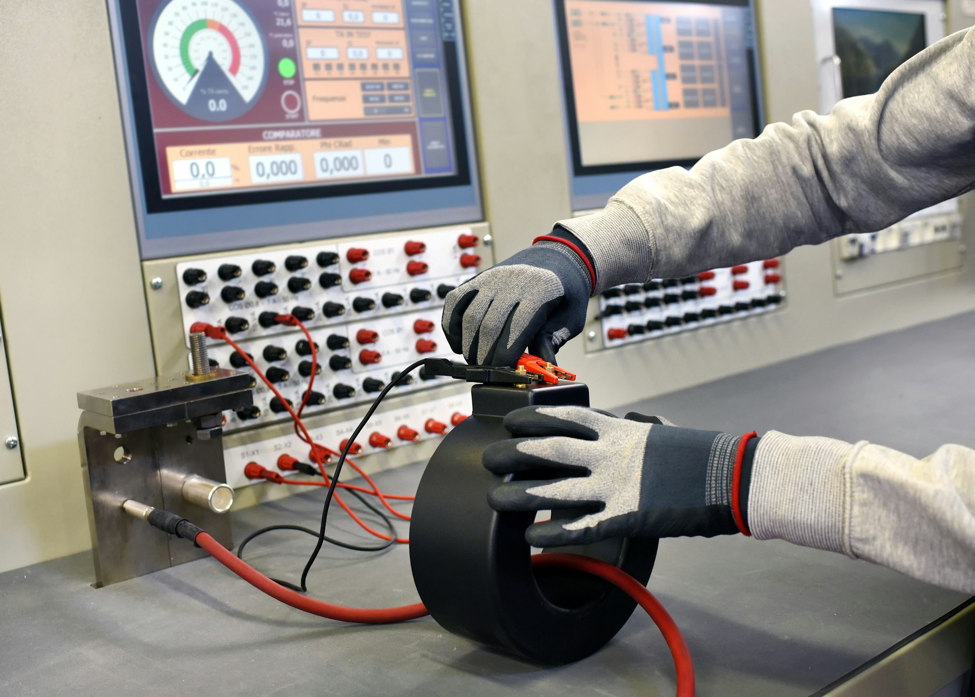
Before an oil-immersed transformer can be put into service, it must undergo comprehensive electrical and mechanical testing to ensure safety, efficiency, and reliability. If these tests are not performed correctly, the transformer may suffer from insulation failure, overheating, or mechanical stress, leading to expensive repairs and operational downtime.
Electrical and mechanical tests before commissioning verify insulation strength, transformer efficiency, core integrity, and mechanical stability. Key tests include insulation resistance, winding resistance, transformer ratio, short-circuit and no-load tests, oil quality analysis, and mechanical stress checks. These ensure the transformer meets operational standards and functions reliably under load conditions.
This guide details the essential pre-commissioning tests, procedures, and acceptance criteria for transformer safety and performance.
A new transformer can be energized without testing.False
Pre-commissioning tests are essential to verify electrical insulation, winding integrity, and mechanical stability before energization.
1. Key Pre-Commissioning Electrical Tests
Electrical tests ensure the insulation strength, winding efficiency, and magnetic performance of the transformer.
A. Insulation Resistance Test (Megger Test)
Purpose: Measures the resistance of insulation between windings and ground to detect moisture, contamination, or insulation deterioration.
| Test Parameter | Acceptable Value |
|---|---|
| HV to LV | >1000 MΩ |
| HV to Ground | >500 MΩ |
| LV to Ground | >200 MΩ |
Procedure:
- Disconnect the transformer from external connections.
- Apply DC voltage (500V–5kV) to windings.
- Measure insulation resistance after 1 minute.
✅ Pass if resistance is high and stable.
❌ Fail if resistance is too low or decreases over time (indicates insulation degradation).
B. Winding Resistance Test
Purpose: Detects loose connections, damaged windings, or high resistance joints in transformer windings.
| Winding Type | Typical Resistance Value (Ω) |
|---|---|
| High Voltage (HV) | 0.1 - 1.0 Ω |
| Low Voltage (LV) | 0.01 - 0.1 Ω |
Procedure:
- Use a DC resistance meter (Kelvin bridge).
- Apply low DC current and measure voltage drop.
- Calculate winding resistance using Ohm’s law:
[R = \frac{V}{I}] - Compare with factory values.
✅ Pass if values match manufacturer specifications.
❌ Fail if resistance is higher than expected (indicates loose connections or damaged windings).
C. Transformer Turns Ratio (TTR) Test
Purpose: Ensures that the transformer maintains correct voltage transformation.
| Voltage Rating | Ratio Tolerance |
|---|---|
| Step-Up Transformer | ±0.5% |
| Step-Down Transformer | ±0.5% |
Procedure:
- Apply a low-voltage AC source to one winding.
- Measure induced voltage in the other winding.
- Calculate the turns ratio:
[TTR = \frac{V{primary}}{V{secondary}}] - Compare with nameplate values.
✅ Pass if deviation is within ±0.5%.
❌ Fail if deviation is excessive (indicates incorrect tap settings or winding issues).
D. Dielectric Strength (Oil Breakdown Voltage) Test
Purpose: Measures the ability of transformer oil to withstand high voltage without breakdown.
| Test Parameter | Acceptable Value |
|---|---|
| Breakdown Voltage | >30 kV |
Procedure:
- Sample transformer oil from the tank.
- Apply increasing voltage between electrodes in an oil testing chamber.
- Record voltage at which breakdown occurs.
✅ Pass if breakdown voltage is >30 kV.
❌ Fail if below limit (indicates moisture contamination, requiring oil filtration or replacement).
E. Short-Circuit and No-Load Loss Test
| Test | Purpose | Acceptance Criteria |
|---|---|---|
| Short-Circuit Test | Measures copper losses and impedance | Within design specs |
| No-Load Test | Measures iron losses and core magnetization | Within design specs |
Procedure:
Short-Circuit Test:
- Apply voltage to HV winding while LV winding is short-circuited.
- Measure power loss (copper loss).
No-Load Test:
- Apply rated voltage to LV winding while HV is open.
- Measure power consumption (iron loss).
✅ Pass if power loss values match factory specifications.
❌ Fail if excessive losses are detected (indicates core damage or improper winding placement).
2. Key Mechanical and Structural Tests
Mechanical tests verify structural integrity, vibration resistance, and cooling system functionality.
A. Core Tightness and Vibration Test
Purpose: Ensures the core is securely clamped to prevent movement during operation.
| Parameter | Acceptance Criteria |
|---|---|
| Vibration Level | Minimal, within design tolerance |
Procedure:
- Check core bolts and clamps for tightness.
- Use vibration sensors to detect abnormal movement.
✅ Pass if vibration is minimal.
❌ Fail if excessive movement is detected (indicates loose core laminations).
B. Cooling System Check
Purpose: Ensures proper heat dissipation to prevent overheating.
| Component | Test Action |
|---|---|
| Radiators | Check for blockages and leaks |
| Oil Circulation | Verify proper flow using temperature sensors |
| Cooling Fans | Test automatic activation and airflow |
✅ Pass if cooling is efficient.
❌ Fail if poor airflow or blockages are found.
3. Final Pre-Commissioning Checks and Safety Tests
Before energization, perform the following final checks:
| Check | Status |
|---|---|
| All electrical tests passed | ✅ / ❌ |
| Cooling system is functional | ✅ / ❌ |
| Insulation resistance is within limits | ✅ / ❌ |
| Bushings and connections are secure | ✅ / ❌ |
| Transformer is grounded properly | ✅ / ❌ |
Once all tests are successfully completed, the transformer can be safely energized under controlled conditions.
How to Perform a Proper Transformer Startup and Load Testing?
Proper startup and load testing of an oil-immersed transformer is critical to ensuring safe, reliable, and efficient operation. If not done correctly, issues such as overloading, insulation failure, overheating, and voltage instability can arise, leading to equipment damage and costly downtime.
Transformer startup and load testing involve systematic energization, voltage stabilization, and controlled load application. The process includes pre-energization checks, gradual voltage ramp-up, monitoring electrical parameters, and ensuring proper load balance. These steps verify transformer performance, efficiency, and safety under real operating conditions.
This guide outlines the best practices, step-by-step procedures, and safety precautions for commissioning a transformer under load.
A transformer can be immediately loaded after installation without startup tests.False
A transformer must go through pre-energization checks, gradual startup, and load testing to ensure safe and efficient operation.
1. Pre-Startup Checks and Preparations
Before energizing the transformer, it must pass a final inspection to confirm that all electrical, mechanical, and safety parameters are within acceptable limits.
A. Visual and Mechanical Inspection
| Check | Action |
|---|---|
| Transformer oil level | Ensure proper oil levels in the conservator tank. |
| Cooling system | Verify radiator fans and oil pumps are operational. |
| Electrical connections | Tighten all high-voltage and low-voltage terminals. |
| Grounding system | Ensure transformer is properly earthed to prevent faults. |
✅ Pass if all components are secured and functioning properly.
❌ Fail if leaks, loose connections, or cooling issues are found (must be corrected before startup).
B. Electrical Testing Before Startup
Before applying voltage, conduct final electrical tests to ensure insulation integrity and operational readiness.
| Test | Purpose | Acceptance Criteria |
|---|---|---|
| Insulation Resistance Test (Megger Test) | Detects moisture or insulation failure | >1000 MΩ |
| Dielectric Oil Breakdown Test | Ensures transformer oil quality | >30 kV |
| Transformer Turns Ratio (TTR) Test | Confirms voltage ratio is correct | ±0.5% of design value |
| Bushing Capacitance Test | Detects insulation degradation in bushings | Within manufacturer limits |
✅ Pass if all electrical parameters meet specifications.
❌ Fail if insulation resistance or oil quality is below standard (requires reconditioning before startup).
2. Step-by-Step Transformer Startup Procedure
After passing all pre-startup checks, energizing the transformer must be done gradually to avoid inrush currents, voltage spikes, or core saturation.
A. Initial Energization – No Load Condition
- Confirm that all circuit breakers and disconnect switches are open.
- Apply voltage gradually using a controlled step-up approach:
- 50% of rated voltage → Hold for 10 minutes.
- 75% of rated voltage → Hold for 10 minutes.
- 100% of rated voltage → Hold for 30 minutes.
- Monitor the following parameters:
- Primary and secondary voltage stability.
- Transformer oil and winding temperature.
- Audible noise (humming should be stable, no unusual vibrations).
✅ Pass if voltage is stable, noise is normal, and temperature rise is within limits.
❌ Fail if sudden voltage fluctuations, abnormal noise, or excessive heating occur (must be investigated before proceeding).
3. Load Testing and Performance Evaluation
Once the transformer is stable under no-load conditions, gradual load application is performed to test its efficiency and operational capacity.
A. Gradual Load Application
| Load Level | Hold Time | Key Observations |
|---|---|---|
| 25% Load | 15 minutes | Check voltage stability and temperature rise. |
| 50% Load | 30 minutes | Ensure cooling system maintains normal operation. |
| 75% Load | 1 hour | Monitor load balancing between phases. |
| 100% Full Load | 4-8 hours | Verify efficiency, losses, and power factor. |
Procedure:
- Gradually increase the load in steps of 25% while monitoring voltage, current, and temperature.
- Ensure balanced loading across all phases to prevent overheating.
- Monitor transformer efficiency using power loss measurements.
✅ Pass if the transformer maintains stable voltage, current, and temperature.
❌ Fail if excessive heating, imbalance, or unexpected voltage drops occur.
B. Power Quality and Performance Verification
The final step in transformer load testing is to analyze power quality and performance under full load.
| Parameter | Ideal Range | Purpose |
|---|---|---|
| Voltage Regulation | ±5% | Ensures stable output voltage |
| Efficiency | 95%-99% | Confirms low energy losses |
| Power Factor | 0.95 - 1.0 | Ensures efficient power usage |
| Oil and Winding Temperature Rise | <85°C | Prevents overheating |
✅ Pass if all performance parameters remain within specifications.
❌ Fail if voltage deviations, excessive losses, or high temperatures occur (may require adjustments to cooling or load balancing).
4. Common Startup and Load Testing Issues & Solutions
| Issue | Possible Cause | Solution |
|---|---|---|
| Excessive Inrush Current | Magnetizing core saturation | Use controlled energization with a step-up voltage approach. |
| Overheating | Cooling system failure | Inspect oil pumps, radiator fans, and ventilation. |
| Voltage Drop Under Load | Tap changer setting incorrect | Adjust on-load tap changer (OLTC) for voltage stability. |
| Load Imbalance | Unequal phase loading | Redistribute load evenly across phases. |
| High No-Load Losses | Core damage or improper installation | Inspect core clamping and alignment. |
✅ Identifying and resolving these issues ensures a smooth transformer startup and reliable performance.
5. Final Acceptance and Commissioning Checklist
Before putting the transformer into full operation, verify that all tests are completed, and the unit meets performance standards.
| Task | Status |
|---|---|
| All electrical tests completed | ✅ / ❌ |
| Cooling system verified and functional | ✅ / ❌ |
| Voltage and current stability confirmed | ✅ / ❌ |
| Load testing completed successfully | ✅ / ❌ |
| All protection relays set and tested | ✅ / ❌ |
| Transformer is ready for continuous operation | ✅ / ❌ |
Conclusion
A successful oil-immersed transformer installation and commissioning process is essential to achieving optimal performance and long-term reliability. By following proper site preparation, careful transportation, precise oil handling, and thorough testing procedures, operators can prevent premature failures and costly downtime.
Investing time and resources in these critical steps ensures that the transformer operates efficiently and safely from day one. Proper commissioning not only extends the transformer's lifespan but also minimizes operational risks and maintenance costs.
Need expert assistance with transformer installation and commissioning? Contact us today for professional guidance and support!
