An On-Load Tap Changer (OLTC) is one of the most important components in medium- and high-voltage transformers, enabling continuous voltage regulation without interrupting power delivery. Understanding how OLTCs work, why they are used, and what benefits they provide is essential for engineers, operators, and project decision-makers. This overview explains the purpose, function, and significance of OLTCs in modern power systems.
What Is an On-Load Tap Changer (OLTC)?
Voltage instability is one of the most common hidden threats in power systems. Load variations, network congestion, and fluctuating generation can cause voltage to drift outside acceptable limits, leading to equipment stress, efficiency loss, and even outages. Shutting down a transformer every time voltage adjustment is needed is impractical and costly. This is where the on-load tap changer becomes essential—it allows voltage regulation while the transformer remains energized and supplying power, ensuring continuity, stability, and reliability.
An On-Load Tap Changer (OLTC) is a mechanical switching device integrated into a power transformer that enables the transformer’s turns ratio—and therefore its output voltage—to be adjusted under load without interrupting power supply. By changing taps on the winding while current is flowing, the OLTC maintains voltage within the standard service range despite load or system voltage fluctuations. It is a critical component in transmission and distribution transformers where voltage stability is required continuously.
To understand why OLTCs are so important, it helps to look deeper into how they work, where they are used, and what risks they mitigate in real power systems.
On-load tap changers allow voltage regulation without interrupting transformer operation.True
OLTCs are specifically designed to change winding taps while current is flowing, maintaining continuous power supply and system stability.
How an OLTC Works in a Power Transformer
An OLTC operates by switching between predefined tap positions on a transformer winding, usually the high-voltage winding. Each tap represents a slightly different turns ratio. When system voltage deviates from the target value, the OLTC moves to a higher or lower tap to correct the output voltage.
The key challenge is that switching must occur without opening the circuit. To achieve this, OLTCs use:
- Transition resistors or reactors to momentarily carry load current
- Diverter switches to manage current transfer between taps
- A selector mechanism to preselect the next tap position
This coordinated process prevents short circuits between taps and avoids supply interruption, even under full load.
Why OLTCs Are Essential for Voltage Regulation
Modern power systems experience constant voltage variation due to:
- Daily load fluctuations
- Renewable energy intermittency
- Long transmission distances
- Reactive power imbalance
Without OLTCs, transformers would operate outside their standard voltage range for extended periods, accelerating insulation aging and increasing losses. OLTCs enable automatic voltage regulation, keeping voltage within IEC and IEEE limits and protecting both the transformer and connected equipment.
Typical Applications of On-Load Tap Changers
OLTCs are most commonly used in:
- Transmission substations
- Large distribution substations
- Industrial power systems with variable loads
- Transformers feeding urban grids or critical infrastructure
They are rarely used in small distribution transformers due to cost and complexity, where off-circuit tap changers are sufficient.
OLTC vs. Off-Circuit Tap Changer
| Feature | On-Load Tap Changer (OLTC) | Off-Circuit Tap Changer |
|---|---|---|
| Operation under load | Yes | No |
| Power interruption required | No | Yes |
| Voltage regulation | Continuous, automatic | Manual, infrequent |
| Complexity | High | Low |
| Typical application | Power transformers | Small distribution units |
This comparison highlights why OLTCs are indispensable in systems where voltage must be controlled dynamically.
Impact of OLTC on Transformer Reliability and Lifetime
By maintaining voltage within the standard service range, OLTCs:
- Reduce insulation electrical stress
- Prevent core saturation
- Minimize excessive losses and heating
- Protect downstream equipment
- Improve overall system stability
However, OLTCs themselves are mechanical systems subject to wear. Proper design, oil quality, monitoring, and maintenance are essential to ensure long-term reliability.
OLTC Control and Automation
Modern OLTCs are equipped with:
- Automatic voltage regulators (AVR)
- Line drop compensation
- Remote monitoring and SCADA integration
- Tap position counters and condition sensors
These features allow utilities to optimize voltage control in real time while minimizing unnecessary tap operations.
Which International Standards Define Service Voltage Limits?
In modern power systems, voltage does not remain perfectly constant. Load fluctuations, network topology, renewable energy integration, and long transmission distances all cause voltage variation. Without clearly defined service voltage limits, transformers and connected equipment would face increased insulation stress, overheating, efficiency loss, and premature failure. International standards play a critical role by defining acceptable voltage ranges that ensure safe, reliable, and interoperable operation across global power networks.
The service voltage limits for transformers are primarily defined by international standards issued by IEC, IEEE, ANSI, and CENELEC, which specify allowable voltage deviations under normal and abnormal operating conditions. These standards align transformer design, testing, and operation with real-world grid behavior, protecting both equipment and system stability.
IEC and IEEE standards define allowable service voltage ranges to ensure safe transformer operation.True
Both IEC 60076 and IEEE C57 standards specify voltage deviation limits that protect insulation, thermal performance, and system reliability.
IEC Standards Defining Service Voltage Limits
The International Electrotechnical Commission (IEC) provides the most widely adopted global framework, especially outside North America.
The key standard is IEC 60076 – Power Transformers, which defines:
- Rated voltage values
- Permissible voltage deviations during continuous operation
- Conditions for overvoltage and undervoltage tolerance
- Associated temperature rise and insulation coordination requirements
IEC 60076 generally allows transformers to operate continuously within ±5% of rated voltage under normal conditions, with short-duration deviations up to ±10%, provided temperature rise and loading limits are respected.
Related IEC standards also influence voltage limits indirectly:
- IEC 60038 (Standard Voltages)
- IEC 60071 (Insulation Coordination)
Together, these standards ensure consistency between system voltage levels and transformer insulation design.
IEEE and ANSI Standards for Service Voltage Limits
In North America and regions following U.S. practices, service voltage limits are defined mainly by IEEE and ANSI standards.
The most important references include:
- IEEE C57.12.00 – General requirements for liquid-immersed transformers
- IEEE C57.12.01 – Dry-type transformer requirements
- ANSI C84.1 – Electric power systems and equipment voltage ratings
ANSI C84.1 defines Range A and Range B voltage limits, specifying acceptable service voltage variation at utilization and distribution levels. Transformers are designed to operate reliably within these defined ranges without loss of performance or life expectancy.
European Grid and Utility Standards
In Europe, IEC standards are complemented by EN (CENELEC) standards and national grid codes.
These documents:
- Adopt IEC voltage limits
- Define utility-specific operating tolerances
- Specify responsibilities between transmission operators, distribution operators, and end users
This layered approach ensures voltage compatibility across interconnected European grids.
Relationship Between Service Voltage Limits and Transformer Design
Service voltage limits directly influence:
- Insulation system design
- Core flux density selection
- Loss guarantees
- Tap changer range and step size
- Thermal margin and cooling design
Transformers are not designed for unlimited voltage flexibility. Operating beyond standardized limits invalidates design assumptions and significantly increases failure risk.
Why International Alignment Matters
Global alignment of service voltage limits allows:
- Cross-border power system interconnection
- Standardized transformer manufacturing
- Easier project approvals
- Reduced risk of misapplication
- Consistent performance expectations
For multinational projects, IEC–IEEE alignment ensures transformers can be safely deployed across different grids with minimal adaptation.
Why Is the Standard Service Voltage Range Important?
In real power systems, voltage is never perfectly stable. Daily load variations, renewable energy fluctuations, transmission distances, and network switching all cause voltage to rise and fall. If transformers were not designed and operated within a clearly defined standard service voltage range, these normal variations would quickly lead to insulation stress, overheating, efficiency loss, and premature failures. The standard service voltage range exists to protect both the transformer and the entire electrical system from these risks.
The standard service voltage range is important because it defines the safe voltage deviation limits within which a transformer can operate continuously while maintaining insulation integrity, thermal stability, efficiency, and long-term reliability. It is a foundational requirement in IEC, IEEE, and ANSI standards and a key assumption behind every transformer’s design, testing, and warranty.
Transformers are designed to operate safely only within defined service voltage limits.True
Insulation levels, core flux density, losses, and temperature rise are calculated based on standardized voltage ranges defined by IEC and IEEE standards.
Protects Insulation and Prevents Premature Aging
Transformer insulation systems are designed according to rated voltage plus a limited margin. Operating within the standard service voltage range ensures:
- Electric field stresses remain within safe limits
- Partial discharge activity stays minimal
- Insulation aging follows predictable thermal life curves
Even small, continuous overvoltage accelerates insulation degradation, while undervoltage combined with high load can increase thermal stress. Respecting the standard voltage range directly extends transformer service life.
Prevents Core Saturation and Abnormal Losses
Transformer cores are optimized for rated voltage and frequency. When voltage exceeds the standard range:
- Magnetic flux density increases nonlinearly
- Core saturation may occur
- No-load losses rise sharply
- Noise and vibration increase
Operating within the standard service voltage range keeps the core in its linear operating region, maintaining efficiency and mechanical stability.
Maintains Thermal Stability and Cooling Margin
Voltage deviations directly affect transformer temperature:
- Overvoltage increases core losses and heating
- Undervoltage often leads to higher current to deliver the same power
The standard service voltage range ensures that winding and oil or resin temperatures remain within design limits, preserving cooling system effectiveness and avoiding accelerated thermal aging.
Ensures Voltage Quality for Connected Equipment
Transformers are voltage-regulating elements for the entire power system. Operating within standard limits:
- Maintains acceptable voltage for motors, drives, and electronics
- Prevents overheating, torque loss, and malfunction of downstream equipment
- Ensures correct operation of protection and control devices
Voltage outside the standard range can propagate problems far beyond the transformer itself.
Preserves Guaranteed Efficiency and Reduces Energy Losses
Transformer efficiency guarantees are valid only within the standard service voltage range. Staying within these limits:
- Keeps core and copper losses within guaranteed values
- Reduces wasted energy
- Lowers operating costs over the transformer’s lifetime
Even modest voltage deviations, if continuous, can result in significant long-term energy losses.
Supports Proper Operation of Tap Changers
On-load and off-circuit tap changers are designed to regulate voltage within the standard service range—not compensate for chronic system voltage problems.
Maintaining voltage within standard limits:
- Reduces tap changer operating frequency
- Minimizes mechanical wear
- Extends maintenance intervals
- Improves overall voltage regulation stability
Ensures Compliance, Warranty Protection, and Asset Value
Operating within the standard service voltage range:
- Ensures compliance with IEC, IEEE, and ANSI standards
- Protects manufacturer warranties
- Meets grid code and regulatory requirements
- Reduces liability in the event of failure
From both technical and commercial perspectives, voltage compliance is essential.
Reduces Failure Risk and Improves System Reliability
Many transformer failures are linked to prolonged operation outside acceptable voltage limits. Staying within the standard range:
- Reduces insulation breakdown risk
- Prevents overheating-related faults
- Minimizes unplanned outages
- Improves overall grid reliability
This is especially critical for substations serving hospitals, data centers, industrial plants, and urban networks.
What Are the Risks of Operating Outside the Standard Voltage Range?
In practical power systems, short-term voltage fluctuations are unavoidable, but continuous operation outside the standard service voltage range creates serious and cumulative risks for transformers and the entire electrical network. International standards such as IEC and IEEE define voltage limits precisely because transformer electrical, thermal, and mechanical designs are based on those boundaries. When a transformer operates beyond them, hidden damage begins long before visible failure occurs.
Operating outside the standard voltage range exposes transformers to accelerated insulation aging, overheating, core saturation, efficiency loss, mechanical stress, and a significantly higher probability of catastrophic failure. These risks affect not only the transformer itself but also downstream equipment, system reliability, regulatory compliance, and total lifecycle cost.
Prolonged operation outside the standard voltage range significantly shortens transformer service life.True
Transformer insulation, thermal limits, and core design are calculated based on standardized voltage limits; exceeding them accelerates aging and failure mechanisms.
Accelerated Insulation Aging and Dielectric Breakdown
Transformer insulation systems are designed for a specific electric field strength. When voltage exceeds standard limits:
- Electrical stress on insulation increases disproportionately
- Partial discharge activity becomes more likely
- Moisture migration and chemical degradation accelerate
- Insulation life is reduced exponentially
Once insulation aging accelerates, it cannot be reversed. Many transformer failures attributed to “aging” are actually the result of long-term overvoltage operation.
Core Saturation, Noise, and Abnormal Heating
Overvoltage pushes the magnetic core beyond its optimal operating region:
- Magnetic flux density rises sharply
- Core saturation occurs during voltage peaks
- No-load losses increase significantly
- Excessive noise and vibration develop
These effects generate localized hot spots in the core and structural components, weakening mechanical integrity over time.
Conclusion
OLTCs are indispensable for transformers operating in environments where voltage stability is essential. By enabling on-load voltage regulation, OLTCs enhance grid reliability, minimize power quality issues, and support efficient system performance. Understanding OLTC types, operation principles, and benefits helps engineers and asset managers make informed decisions when selecting or maintaining power transformers.
FAQ
Q1: What is an On-Load Tap Changer (OLTC)?
An On-Load Tap Changer (OLTC) is a device fitted to a power transformer that allows the transformation ratio to be changed while the transformer remains energized and supplying load. Its main function is to regulate output voltage automatically or manually in response to load variations or grid voltage fluctuations, without interrupting power supply.
OLTCs are commonly used in power transformers and large distribution transformers connected to transmission and sub-transmission networks where stable voltage is critical.
Q2: Why is an OLTC important in power systems?
Voltage in power systems varies due to changing load demand, line losses, and network conditions. An OLTC helps to:
Maintain stable secondary voltage
Improve power quality
Reduce voltage drop during peak loads
Protect equipment from overvoltage or undervoltage
Support grid reliability and operational flexibility
Without an OLTC, voltage regulation would require outages or external compensation equipment.
Q3: How does an OLTC work?
An OLTC operates by switching between different tapping points on the transformer winding. During tap change operation:
The OLTC momentarily transfers current through transition resistors or reactors
This prevents short circuits or open circuits between taps
The tap change occurs smoothly while the load remains connected
OLTCs can be motor-driven and automatically controlled using voltage regulators that monitor system voltage in real time.
Q4: Where is the OLTC installed in a transformer?
OLTCs are typically installed on the high-voltage winding of a transformer because:
The current is lower compared to the LV side
Switching stresses are reduced
Equipment size and losses are minimized
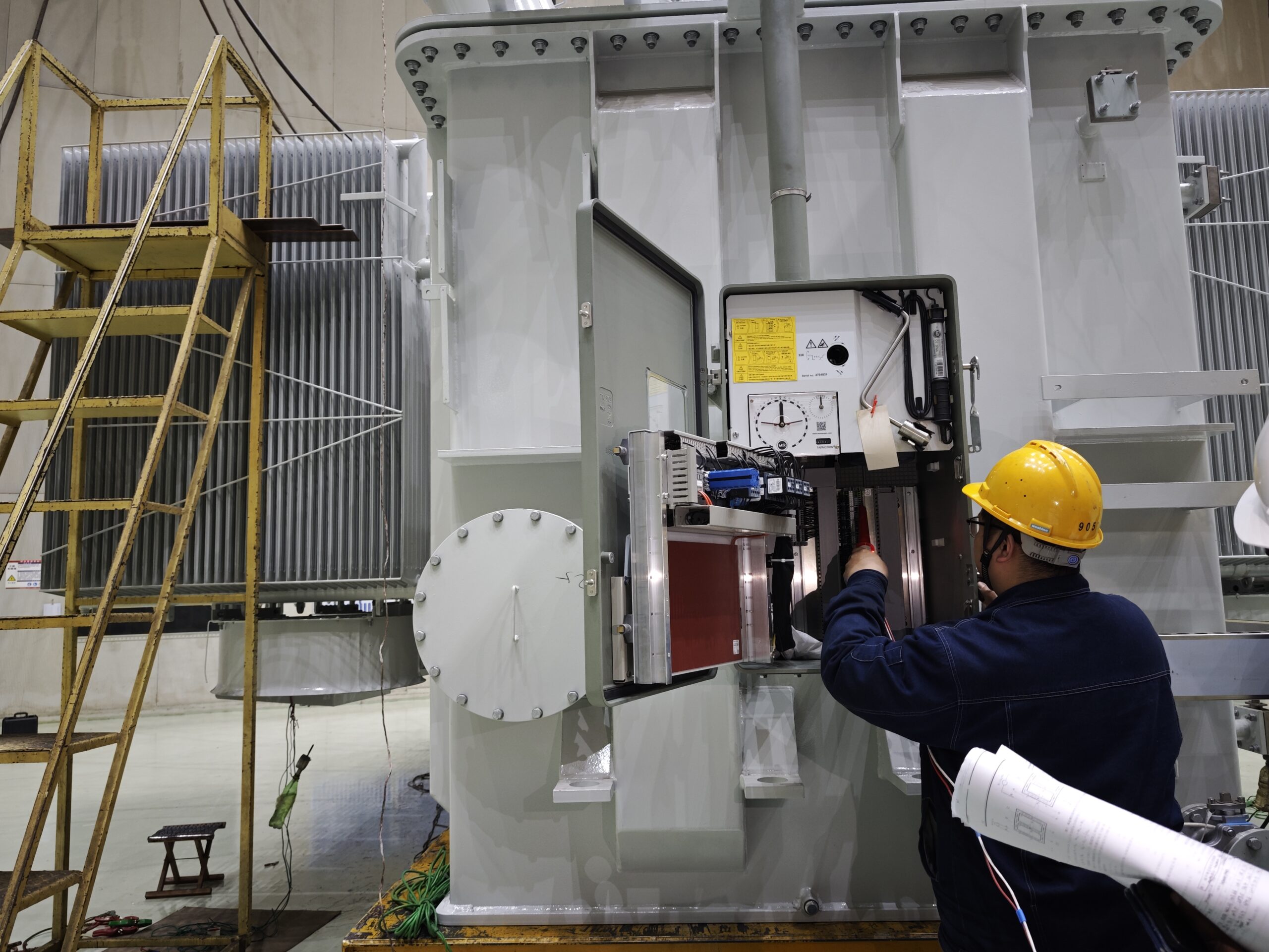
In oil-immersed transformers, the OLTC is usually located in a separate oil compartment to prevent contamination of the main transformer insulation.
Q5: What are the main types of OLTCs?
The two most common OLTC designs are:
Resistor-type OLTC – Uses transition resistors to limit circulating currents during tap change; widely used in utility transformers.
Reactor-type OLTC – Uses reactors instead of resistors; more complex but suitable for certain high-power applications.
Modern OLTCs may also include vacuum interrupters to reduce arcing and extend maintenance intervals.
Q6: What is the difference between OLTC and off-load tap changers?
OLTC:
Tap change under load
No power interruption
Higher cost and complexity
Off-load tap changer (DETC):
Tap change only when transformer is de-energized
Lower cost
Used in smaller or less critical applications
OLTCs are preferred where continuous voltage regulation is required.
Q7: What maintenance does an OLTC require?
OLTCs experience mechanical wear and electrical arcing, so they require regular maintenance, including:
Contact inspection and replacement
Oil filtration or replacement in the OLTC compartment
Drive mechanism lubrication
Electrical and timing checks
Proper OLTC maintenance is essential to avoid transformer failures, as OLTC-related issues account for a significant percentage of transformer faults.
References
IEC 60214 – Tap Changers
https://webstore.iec.ch/publication/616
IEC 60076 – Power Transformers
https://webstore.iec.ch/publication/602
IEEE Guide for Tap Changer Applications
https://ieeexplore.ieee.org
MR (Maschinenfabrik Reinhausen) – OLTC Fundamentals
https://www.reinhausen.com
Schneider Electric – Voltage Regulation in Transformers
https://www.se.com
Electrical Engineering Portal – OLTC Explained
https://electrical-engineering-portal.com
Doble Engineering – OLTC Maintenance and Diagnostics
https://www.doble.com