Commissioning a new power transformer is a critical step in ensuring reliable performance, safety, and long service life. It involves systematic inspections, electrical testing, and operational checks before the transformer is energized and connected to the grid. Proper commissioning helps detect manufacturing defects, transport damages, or installation errors that could otherwise lead to costly failures.
What Is a Pre-Commissioning Inspection for Transformers and Why Is It Essential?
Before a transformer is energized and placed into service, it must undergo a pre-commissioning inspection. This process ensures that the transformer has been transported, installed, and prepared correctly, without damage or assembly errors that could cause premature failure. If skipped, undetected issues such as insulation breakdown, improper grounding, oil leaks, or faulty protection devices can lead to catastrophic failures, safety hazards, or costly downtime. A structured inspection verifies compliance with standards, guarantees operational readiness, and prevents expensive service disruptions.
A pre-commissioning inspection for transformers is a structured process of checking mechanical, electrical, and safety conditions before energization. It includes visual inspections, insulation resistance tests, oil quality verification, winding resistance measurement, ratio and polarity checks, and validation of cooling, protection, and control systems to ensure safe and reliable operation.
A successful pre-commissioning inspection not only protects equipment investment but also establishes a baseline reference for future maintenance and troubleshooting, making it a critical step in transformer lifecycle management.
Pre-commissioning inspection is optional and can be skipped if the transformer passes factory tests.False
Even if a transformer passes factory acceptance tests, installation, transportation, and site conditions can introduce new risks. Pre-commissioning inspection is mandatory for safe energization.
1. Scope of Pre-Commissioning Inspection
Pre-commissioning involves both mechanical and electrical checks:
Mechanical Checks:
- Verify transformer tank integrity, sealing gaskets, and absence of oil leaks.
- Confirm correct assembly of bushings, radiators, conservator, and cooling fans.
- Ensure silica gel breather is fresh, oil level in conservator is correct, and pressure relief devices are functional.
- Check grounding connections and support structures.
Electrical Checks:
- Measure insulation resistance (IR) using a megger.
- Perform transformer turns ratio (TTR) test.
- Check winding resistance and polarity.
- Verify vector group and phase displacement.
- Test current transformers (CTs), potential transformers (PTs), and protection relays.
2. Key Pre-Commissioning Tests
| Test/Inspection | Purpose | Acceptable Criteria |
|---|---|---|
| Visual inspection | Detect transport/installation damage | No cracks, leaks, defects |
| Insulation Resistance (IR) | Check winding insulation condition | As per IEEE/IEC minimum values |
| Winding Resistance | Identify loose connections or shorted turns | Within design tolerance |
| Turns Ratio (TTR) Test | Confirm correct voltage transformation ratio | ≤ 0.5% deviation |
| Vector Group Test | Verify correct phase displacement | Matches nameplate |
| Oil Quality (for oil-filled) | Ensure dielectric strength & moisture content are within limits | BDV ≥ 60 kV, moisture ≤ 30 ppm |
| Protection Device Checks | Test PRV, Buchholz relay, temperature sensors, and alarms | Functional |
| Functional Checks of Cooling | Verify fans, pumps, and control circuits | Normal operation |
3. Environmental and Safety Considerations
- Ensure adequate ventilation or cooling in the transformer room.
- Confirm fire safety compliance (oil containment pits, firewalls, extinguishers).
- Verify noise levels and shielding in sensitive areas.
- Confirm compliance with IEC 60076, IEEE C57, and local electrical codes.
4. Documentation and Reporting
A pre-commissioning inspection must include:
- A checklist of completed tests.
- Test results benchmarked against standards.
- Photos and records of initial conditions.
- A formal approval to energize.
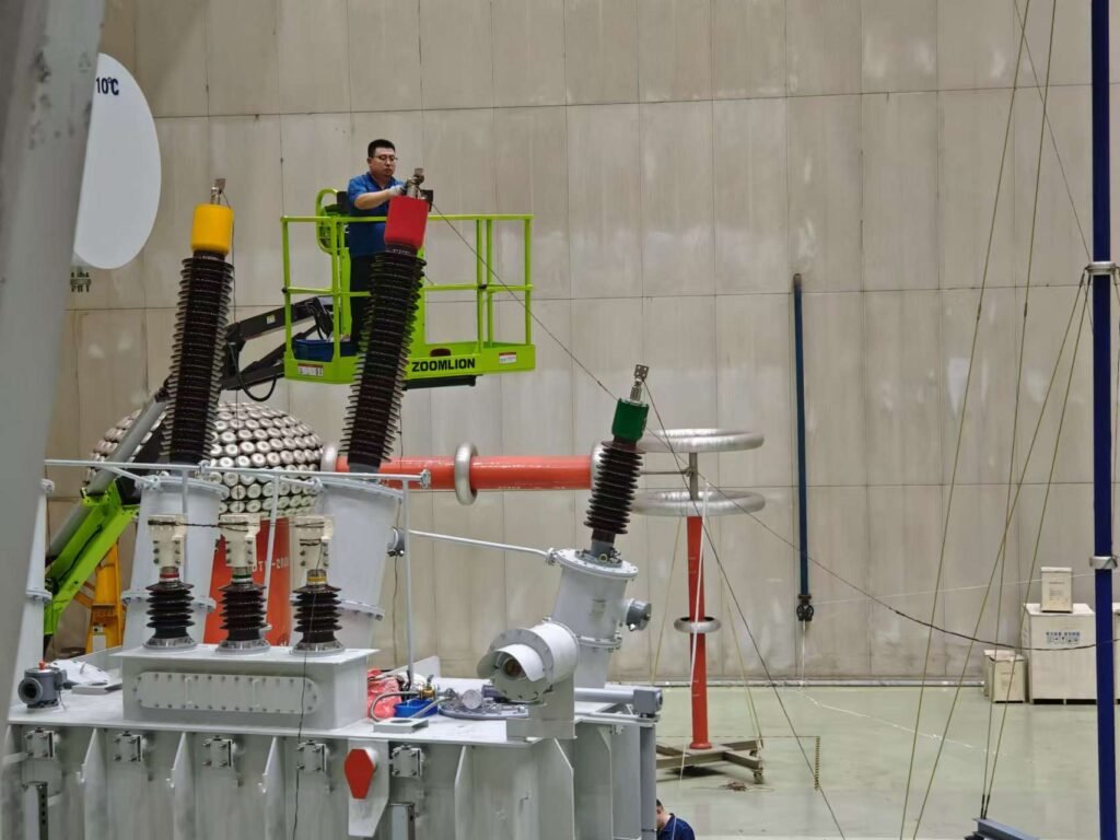
What Electrical and Mechanical Tests Are Performed on Transformers Before Commissioning?
Before a transformer is energized, it undergoes a series of electrical and mechanical tests to ensure that it is free from defects, correctly installed, and safe to operate. If these tests are skipped or inadequately performed, there is a significant risk of electrical faults, overheating, mechanical breakdown, or catastrophic failure, which can cause costly downtime and serious safety hazards. Conducting these tests provides assurance that the transformer meets IEEE, IEC, and ANSI standards for operational reliability.
Electrical and mechanical tests on transformers are procedures carried out before commissioning to verify insulation quality, winding integrity, correct transformation ratio, polarity, phase displacement, oil or insulation condition, and the physical soundness of mechanical parts such as bushings, radiators, cooling fans, conservators, and grounding. Together, these tests confirm the transformer’s readiness for safe energization.
By combining both electrical and mechanical evaluations, operators reduce risk, establish baseline values for future monitoring, and extend the transformer's service life.
Electrical tests alone are sufficient for transformer commissioning.False
Both electrical and mechanical tests are mandatory. Mechanical failures such as oil leaks or faulty bushings can cause operational risks even if electrical parameters are normal.
1. Electrical Tests
These tests evaluate the transformer's dielectric strength, insulation quality, and electrical performance.
| Test | Purpose | Typical Acceptance Criteria |
|---|---|---|
| Insulation Resistance (IR) | Checks insulation health of windings using megger | Must meet IEEE/IEC minimum values |
| Winding Resistance | Detects loose connections, shorted turns, or poor contacts | Within manufacturer’s tolerance |
| Turns Ratio Test (TTR) | Verifies correct voltage ratio between windings | ≤ 0.5% deviation from design |
| Polarity and Vector Group | Confirms correct phase relationship | Must match nameplate |
| Excitation Current Test | Ensures magnetizing current is within limits | Within design range |
| Power Factor / Tan δ Test | Measures insulation loss angle (dissipation factor) | ≤ 1% for new transformers |
| Dielectric Tests (Hi-Pot/BDV) | Checks insulation withstand capability | Passes required test voltage |
| Sweep Frequency Response Analysis (SFRA) | Detects winding deformation or displacement | Must match baseline |
| Capacitance and Dissipation Factor | Evaluates bushing and insulation condition | Within IEC/IEEE limits |
| Oil Tests (if oil-filled) | Measures dielectric strength (BDV), water content, and DGA gases | BDV ≥ 60 kV, moisture ≤ 30 ppm |
2. Mechanical Tests
Mechanical checks ensure that the structural integrity and cooling systems are properly installed and operational.
| Mechanical Inspection | Purpose | Key Items Checked |
|---|---|---|
| Visual Inspection | Detects physical damage, cracks, oil leaks | Tank, conservator, bushings |
| Oil Level & Sealing | Confirms correct oil levels and no leaks | Conservator, gaskets, joints |
| Bushing Integrity | Ensures bushings are crack-free and correctly mounted | HV & LV bushings |
| Cooling System Check | Tests fans, pumps, and radiators for proper operation | ONAN/ONAF/OFAF systems |
| Breather Inspection | Ensures silica gel is fresh and not saturated | Breather and desiccant |
| Pressure Relief Devices | Confirms PRV and Buchholz relay functionality | Audible/visual alarms |
| Grounding | Ensures correct earthing and bonding | Tank, neutral, and surge protection |
| Fastener Tightness | Confirms all bolts, clamps, and connections are secure | Tank cover, bushing clamps |
3. Integration of Electrical and Mechanical Tests
- Electrical tests verify internal integrity and insulation.
- Mechanical tests verify external soundness and safety systems.
Together, they prevent failures such as:
- Short circuits from degraded insulation.
- Oil leaks leading to fire hazards.
- Overheating due to non-functional radiators or fans.
- Bushing explosions caused by unnoticed cracks.
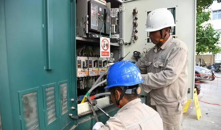
What Protection and Control System Checks Are Required Before Transformer Commissioning?
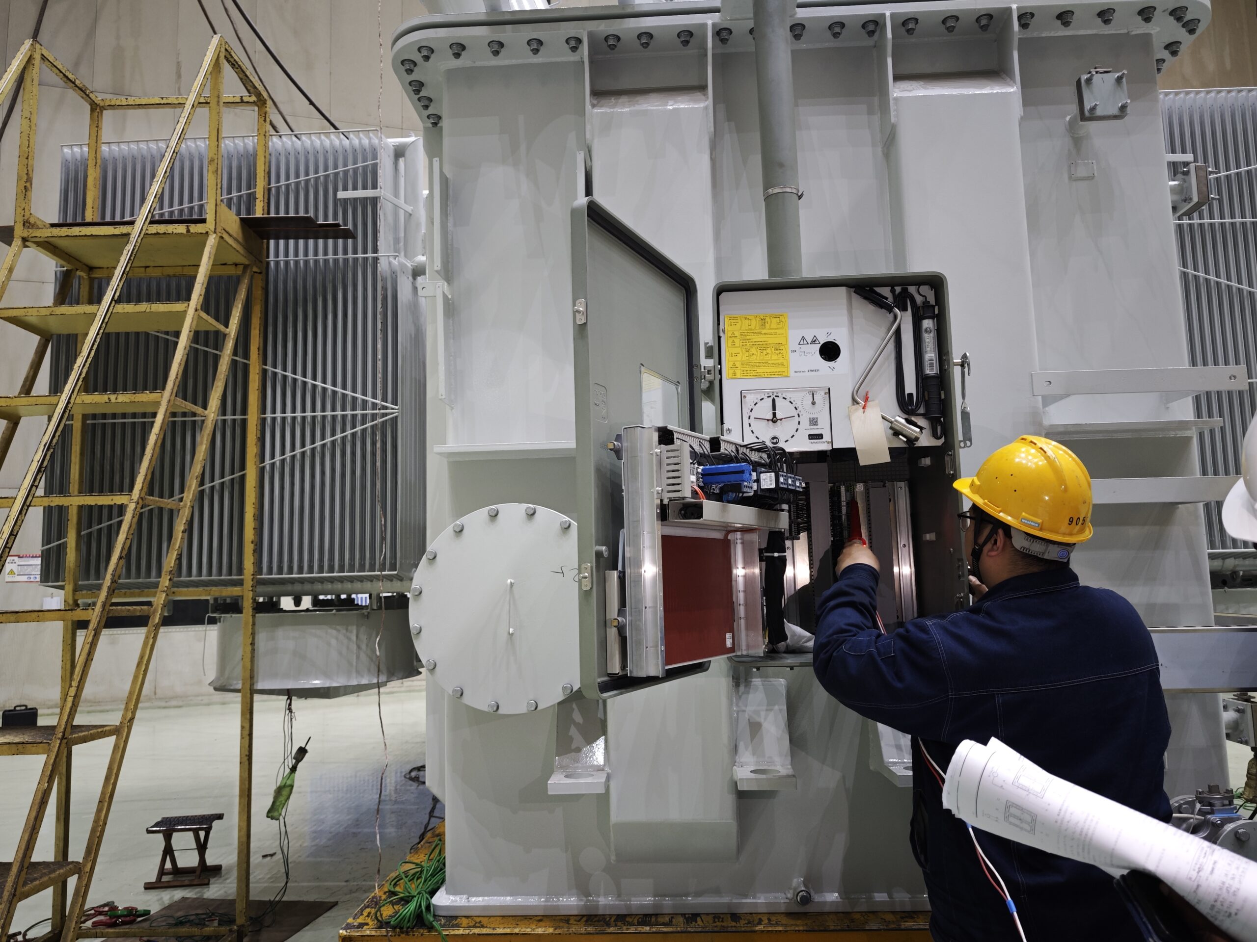
Before energizing a power transformer, the protection and control systems must be thoroughly checked. If these systems are not correctly configured or tested, the transformer may remain unprotected against short circuits, overloads, or abnormal conditions, which can lead to catastrophic failures, extended outages, or fire hazards. Proper commissioning ensures that every relay, sensor, trip circuit, and communication channel functions as designed.
Protection and control system checks for transformers involve validating relay settings, trip circuits, alarms, monitoring devices, SCADA communication, and interlocking logic to confirm that the transformer will be safely isolated in case of abnormal conditions such as overcurrent, differential faults, over-temperature, or Buchholz relay activation. These checks guarantee safe, reliable, and automatic protection during operation.
When done correctly, these checks ensure seamless coordination with upstream and downstream devices, reducing both equipment damage and system downtime.
Transformers can be safely energized without verifying protection and control systems.False
Protection and control system checks are mandatory to prevent severe damage during faults. Energizing without verification poses significant safety and reliability risks.
1. Protection System Checks
Key relays and sensors that protect the transformer must be validated:
| Protection Function | Purpose | Check Performed |
|---|---|---|
| Differential Protection (87T) | Detects internal winding faults | Primary injection test, relay response check |
| Overcurrent & Earth Fault Protection (50/51/50N/51N) | Protects against external faults and overloads | Relay pickup and timing verification |
| Overvoltage / Undervoltage Relays (59/27) | Prevents insulation stress or underperformance | Apply test voltages to confirm operation |
| Buchholz Relay (oil-filled units) | Detects gas accumulation or sudden pressure | Simulate gas/fault to test alarms and trip |
| Pressure Relief Device | Protects against tank rupture | Mechanical trip and alarm function check |
| Over-temperature Relays | Prevents overheating damage | Inject simulated signals from RTDs or sensors |
| Restricted Earth Fault (REF) | Sensitive earth fault detection | Stability and sensitivity testing |
| Surge Protection (Lightning Arresters) | Protects against transient overvoltages | Visual inspection and leakage current monitoring |
2. Control System Checks
These confirm that the transformer’s control logic and operational sequences are functional:
- Trip Circuit Supervision – Verifies trip coil continuity and health.
- Breaker Control Logic – Tests open/close signals, interlocks, and status feedback.
- Tap Changer Control (OLTC) – Confirms automatic/manual tap operations and limits.
- Alarm Circuits – Ensures audible/visual alarms activate correctly for all abnormal events.
- Annunciation Panels – Validate correct fault/event indications.
- Local/Remote Control Selector – Tests switch-over between local panel and SCADA.
3. SCADA and Communication Checks
For modern facilities, transformer protection is integrated with supervisory systems:
| Test Item | Purpose | Verification Method |
|---|---|---|
| SCADA Communication | Ensures remote monitoring/control | Protocol testing (IEC 61850, Modbus, DNP3) |
| Event & Fault Logging | Records disturbances for diagnostics | Trigger fault simulation and review logs |
| Time Synchronization | Aligns event records with system clock | GPS or NTP synchronization test |
| Remote Commands | Confirms remote trip, close, and reset | Issue test commands under supervision |
4. Interlocking and Coordination
- Busbar Protection Coordination – Prevents false trips during external faults.
- Breaker Fail Protection – Ensures backup trip occurs if breaker fails.
- Transformer-Feeder Interlocking – Confirms correct logical sequence for safe switching.
- Load Shedding Schemes – Validates automatic unloading under stress.
What Are the Key Oil vs. Dry Type Transformer Considerations for Users?
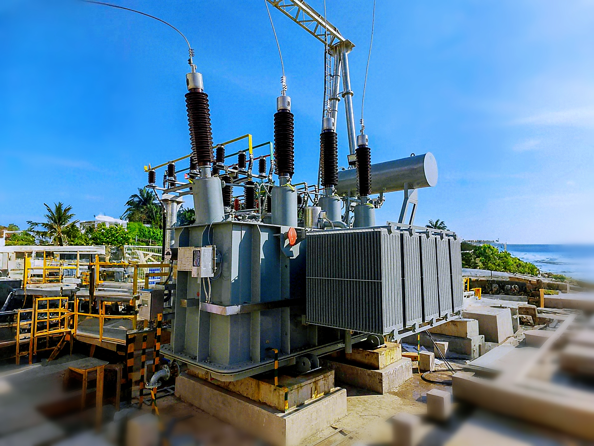
Choosing between an oil-immersed transformer and a dry-type transformer is one of the most important decisions in power system design. Selecting the wrong type can lead to safety risks, excessive costs, or reduced service life. Oil-filled units provide higher power density, better cooling, and lower initial cost, while dry-type units offer improved fire safety, easier installation in buildings, and lower environmental risks.
Oil-immersed transformers use liquid dielectric (typically mineral oil or ester) for insulation and cooling, making them ideal for outdoor, high-voltage, and high-capacity applications, whereas dry-type transformers use solid insulation and air cooling, making them safer and more suitable for indoor or environmentally sensitive installations.
For engineers, facility managers, and investors, understanding these differences ensures optimal performance, safety, and lifecycle cost management.
Oil-immersed transformers are always safer than dry-type transformers.False
Oil-immersed transformers carry a higher risk of fire, explosion, and environmental contamination compared to dry-type units, which are generally safer for indoor use.
1. Technical Comparison
| Aspect | Oil-Immersed Transformer | Dry-Type Transformer |
|---|---|---|
| Cooling Method | Mineral oil or ester fluids for cooling and insulation | Air (natural or forced) with solid insulation |
| Power Range | Up to 1000 MVA or more | Typically up to 30 MVA |
| Voltage Range | Suitable for up to 765 kV | Usually limited to 36 kV |
| Efficiency | Higher efficiency, lower losses | Slightly lower efficiency |
| Size/Weight | More compact for same rating | Bulkier, heavier per kVA |
| Maintenance | Requires oil monitoring (dissolved gas, moisture, acidity) | Minimal, mostly dust removal and inspection |
| Lifespan | 25–40 years with proper oil management | 20–30 years depending on insulation class |
| Fire Risk | Higher (flammable oil) | Very low (self-extinguishing insulation) |
| Environmental Risk | Oil leaks, PCB history, soil/water contamination | Environmentally safer, no liquid spillage |
| Installation Location | Outdoors, substations, industrial yards | Indoors, basements, commercial buildings |
2. Application Suitability
Oil-Immersed Transformers
- High-voltage transmission and distribution networks
- Large industrial plants and power generation facilities
- Outdoor substations with space for fire protection measures
Dry-Type Transformers
- High-rise buildings, hospitals, shopping malls
- Underground substations or confined spaces
- Renewable energy installations (e.g., wind turbines, solar farms)
- Environments with strict fire safety or environmental regulations
3. Cost and Lifecycle Considerations
| Cost Factor | Oil-Immersed | Dry-Type |
|---|---|---|
| Initial Purchase | Lower per kVA | Higher per kVA |
| Installation | Requires fire protection, oil containment | Simple indoor installation |
| Operation | Efficient but requires oil management | Lower maintenance cost |
| End-of-Life | Oil disposal and recycling required | Easier, more eco-friendly disposal |
| Total Lifecycle Cost | Lower for very large units | Competitive for medium/low power ranges |
4. Safety and Regulatory Compliance
- Oil-filled units must follow NFPA, IEEE, and IEC fire safety standards with oil catch basins, explosion vents, and fire suppression systems.
- Dry-type units comply more easily with building codes, green building standards (LEED, BREEAM), and urban planning regulations due to their reduced hazard profile.
What Are the Proper Energization Procedures for Power Transformers?
Incorrect transformer energization can lead to inrush current, insulation failure, winding damage, or catastrophic outages. Such failures not only cause equipment loss but also disrupt power supply to critical loads. To prevent these risks, engineers follow strict energization procedures that balance safety, reliability, and performance.
Proper energization procedures for transformers involve pre-commissioning inspection, verification of connections and protection systems, step-by-step voltage application, monitoring of inrush current and operational parameters, and confirming stable operation before loading.
Following standard energization steps ensures safe commissioning, extended transformer life, and compliance with IEEE/IEC regulations.
Transformers can be energized without pre-checks if they are new from the factory.False
Even new transformers require thorough inspection, insulation resistance testing, and protection relay verification before energization to prevent early failures.
1. Pre-Energization Checks
Before energization, all critical conditions must be verified:
- Mechanical inspection: Ensure no oil leaks (for oil-immersed units), radiator valves are open, silica gel breathers are active, and nameplate ratings match system design.
Electrical checks:
- Insulation resistance test (IR)
- Winding resistance measurement
- Turns ratio test (TTR)
- Dielectric test (if required)
- Protection verification: Test relays, Buchholz relay, pressure relief devices, and circuit breakers.
- Grounding: Confirm neutral and body grounding connections.
2. Energization Sequence
The energization process is performed step by step:
| Step | Procedure | Purpose |
|---|---|---|
| 1 | Confirm transformer is isolated and grounded | Personnel safety |
| 2 | Disconnect neutral/grounding jumpers as per test sequence | Prepare for live energization |
| 3 | Ensure tap changer is set to nominal position | Voltage matching |
| 4 | Apply voltage from HV side gradually (via circuit breaker) | Minimize inrush |
| 5 | Monitor inrush current, voltage, and core magnetization | Protect windings |
| 6 | Keep transformer energized at no-load for 1–2 hours | Stabilize oil/dry insulation |
| 7 | Connect LV side and gradually apply load | Smooth loading transition |
| 8 | Record all parameters (current, temperature, vibrations, protection relay status) | Verification of performance |
3. Inrush Current Considerations
- Transformers draw high inrush current (up to 8–12 times rated current) when first energized.
Controlled energization methods:
- Closing breaker at voltage zero-crossing
- Pre-insertion resistors/reactors
- Sequential energization of three phases
- Inrush must be monitored to avoid misoperation of protective relays.
4. Safety Protocols During Energization
- All operations must be performed under a permit-to-work (PTW) system.
- Operators must wear arc-flash and HV safety gear.
- Maintain safe clearance distances per IEEE/IEC/NFPA standards.
- Emergency disconnection plan must be in place.
5. Post-Energization Monitoring
After initial energization:
- Check oil level, oil pressure, and temperature rise.
- Measure noise, vibration, and harmonic distortion.
- Verify correct functioning of cooling fans/pumps.
- Log data for baseline performance records.
What Is Post-Commissioning Monitoring of Transformers and Why Is It Important?
Many transformer failures occur not during installation or energization, but in the first few weeks of service. Small issues such as overheating, abnormal vibrations, oil leaks, or improper protection relay settings can escalate into costly downtime or permanent damage if left unchecked. This is why post-commissioning monitoring is a critical stage in transformer lifecycle management.
Post-commissioning monitoring refers to the continuous observation and analysis of transformer performance parameters—such as temperature, oil condition, load profile, and protective relay activity—during the early operation period to ensure stability, reliability, and long-term safety.
It provides operators confidence that the transformer is performing according to design specifications and allows early detection of hidden faults.
Once a transformer passes pre-commissioning and energization tests, no further monitoring is needed.False
Transformers require continuous post-commissioning monitoring to detect abnormal thermal, electrical, or mechanical behavior that might not appear during short-term tests.
1. Key Objectives of Post-Commissioning Monitoring
- Confirm transformer operates within rated voltage, current, and temperature limits
- Validate cooling systems (fans, pumps, radiators) function automatically
- Monitor oil and insulation health (for oil-filled types)
- Ensure protection and control systems respond correctly
- Establish baseline performance data for predictive maintenance
2. Parameters to Monitor After Commissioning
| Parameter | Why It Matters | Monitoring Method |
|---|---|---|
| Winding & Oil Temperature | Prevent insulation damage | Temperature gauges, sensors, SCADA |
| Load Current & Voltage | Avoid overload and imbalance | Digital meters, SCADA logging |
| Oil Level & Pressure | Maintain cooling and insulation | Oil gauges, DGA sensors |
| Dissolved Gas Content | Detect early faults (arcing, overheating) | Online DGA monitoring |
| Partial Discharge (PD) | Identify insulation weakness | PD sensors, acoustic monitoring |
| Vibration & Noise | Spot mechanical loosening or resonance | Vibration sensors, acoustic analysis |
| Cooling System Status | Confirm automatic operation | Fan/pump status checks |
| Protection Relay Events | Verify settings and avoid nuisance trips | Relay event recorder |
3. Early Monitoring Period (First 30 Days)
- Run transformer at 50–70% load initially before gradually reaching full load
- Log daily readings of temperature, oil, and load current
- Perform weekly infrared thermography to detect hot spots in bushings, radiators, and connections
- Conduct oil sample analysis within the first month to establish reference DGA values
4. Long-Term Post-Commissioning Monitoring
After initial stabilization:
- Monthly trending of key parameters (temperature, losses, load factor)
- Semi-annual oil analysis (DGA, moisture content, acidity)
- Annual protection relay testing and functional checks
- Integration into SCADA or IoT-based predictive monitoring platforms for real-time alerts
5. Benefits of Post-Commissioning Monitoring
- Early fault detection prevents catastrophic failures
- Baseline data enables predictive maintenance planning
- Ensures regulatory compliance (IEEE, IEC, ISO standards)
- Extends transformer service life by 20–30%
- Reduces lifecycle costs and unplanned downtime
Conclusion
Proper commissioning of a power transformer ensures that it operates safely and efficiently from day one. By performing thorough inspections, electrical testing, protection verification, and careful energization, potential risks can be minimized. This process not only protects the transformer investment but also safeguards the stability of the power system.
FAQ
Q1: What does commissioning a power transformer involve?
Commissioning a power transformer involves performing inspections, electrical and mechanical tests, oil quality analysis, protection system checks, and ensuring compliance with design specifications before energizing the unit. This ensures safety, reliability, and long-term performance.
Q2: What pre-commissioning checks are essential?
Pre-commissioning checks include verifying nameplate details, confirming correct vector group, checking insulation resistance, performing winding resistance tests, ensuring proper grounding, and validating cooling system functionality. Oil level, dielectric strength, and moisture content must also be tested in oil-filled units.
Q3: What electrical tests are performed during commissioning?
Critical tests include insulation resistance, transformer turns ratio (TTR), polarization index, winding resistance, short-circuit impedance, and dielectric tests. Protection relays and circuit breakers associated with the transformer are also tested for correct operation.
Q4: Why is oil analysis important before commissioning?
For oil-filled transformers, oil analysis ensures dielectric strength, moisture content, and dissolved gases are within limits. This prevents premature failure, insulation breakdown, and overheating issues once the transformer is in service.
Q5: What are the final steps before energizing a transformer?
Final steps include verifying all test results, ensuring protective relays and alarms are functional, checking cooling fans/pumps, tightening connections, and removing all earthing connections used during testing. Energization should be gradual, with continuous monitoring of load, voltage, and temperature.
References
IEEE Std C57.12.90 – Standard Test Code for Power Transformers: https://ieeexplore.ieee.org
IEC 60076 – Power Transformer Testing Standards: https://webstore.iec.ch
NEMA – Transformer Installation & Commissioning Guidelines: https://www.nema.org
Electrical4U – Transformer Commissioning Procedure: https://www.electrical4u.com
EEP – Power Transformer Commissioning Checklist: https://electrical-engineering-portal.com
All About Circuits – Transformer Testing & Maintenance Basics: https://www.allaboutcircuits.com