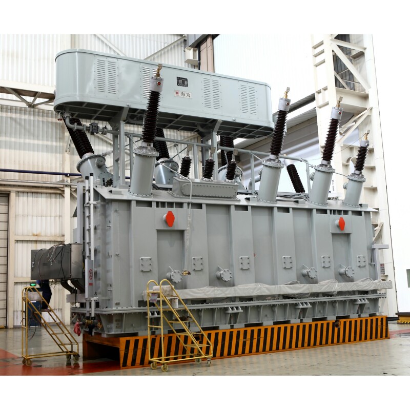
Before a power transformer leaves the manufacturing facility, it must undergo rigorous testing to ensure safety, performance, and compliance with international standards such as IEC, IEEE, or ANSI. Factory Acceptance Tests (FAT) serve as a critical checkpoint to verify that the transformer operates according to design specifications and is free of manufacturing defects. These tests offer peace of mind for both manufacturers and customers by minimizing the risk of failures during installation or operation.
What Is the Purpose of FAT for Power Transformers?
Before a power transformer leaves the factory, it must undergo a rigorous verification process known as Factory Acceptance Testing (FAT). This is not a formality—it is a critical engineering checkpoint that confirms whether the unit meets the design specifications, safety standards, and functional requirements agreed upon in the contract.
FAT is conducted to validate the electrical, mechanical, thermal, and operational performance of a power transformer before shipment. It ensures compliance with IEC/IEEE standards, confirms that manufacturing tolerances have been met, and provides buyers the confidence that the equipment is free from defects. FAT also allows customer representatives to witness the results and approve the unit before dispatch.
This process reduces the risk of field failure, minimizes site commissioning delays, and is essential for quality assurance in high-voltage equipment procurement.
FAT is an optional procedure and not necessary for power transformers.False
Factory Acceptance Testing (FAT) is a mandatory procedure in most power transformer projects to validate performance, quality, and contract compliance before delivery.
🔍 Key Objectives of FAT
| Objective | Benefit |
|---|---|
| Verify performance parameters | Confirms no-load loss, load loss, impedance, insulation values |
| Detect manufacturing defects | Identifies internal faults, insulation flaws, or assembly errors |
| Validate contract compliance | Ensures ratings, taps, bushings, and materials match P.O. |
| Demonstrate functional readiness | Confirms OLTC operation, relay settings, gauges, alarms |
| Enable client approval | Witness testing ensures buyer accepts unit before shipment |
⚙️ Typical FAT Test Scope (per IEC 60076 & IEEE C57)
| Test Type | Purpose |
|---|---|
| Measurement of Resistance | Check winding resistance symmetry and connections |
| Turns Ratio & Polarity Test | Confirms correct winding configuration and tap accuracy |
| Insulation Resistance Test | Ensures dry and clean insulation environment |
| Dielectric Strength (Induced & Impulse Tests) | Verifies BIL withstand capability |
| Load Loss & Impedance Voltage | Measures copper losses and leakage reactance |
| No-Load Loss & Excitation Current | Validates core quality and magnetic behavior |
| Temperature Indicators & OLTC Function Test | Verifies control systems and moving parts |
| Partial Discharge Test | Ensures insulation integrity under high voltage stress |
🧠 Why FAT Is Critical for Buyers
| Reason | Impact on Project |
|---|---|
| Mitigates Installation Delays | Issues are caught at factory, not during energization |
| Supports Grid Reliability | Reduces risk of early-life failure or misconfiguration |
| Assures ROI and Warranty Validity | Buyer has documented proof of performance |
| Simplifies Commissioning | Factory-tested devices integrate more smoothly at site |
| Strengthens Legal Contract Enforcement | FAT report becomes binding QC document |
🛠️ Optional Additional Tests in FAT (per contract)
| Optional Test | Purpose |
|---|---|
| Sound Level Measurement | Ensures noise meets substation limits |
| Temperature Rise Simulation | Confirms thermal limits of windings under load |
| Core Grounding Test | Detects unwanted circulating current paths |
| Sweep Frequency Response (SFRA) | Establishes mechanical integrity baseline |
| Gas & Oil Leak Test | Validates tank welding, gaskets, and oil tightness |
🧾 What Happens After FAT?
- Test reports are signed by manufacturer and client witness
- Corrective actions (if needed) are agreed upon before shipment
- Packing list and shipping docs are finalized based on approved unit
- Transport insurance is activated after FAT clearance
- Site team is briefed using FAT data to prepare for commissioning
💬 Engineer's View
“FAT gives us complete confidence. We verify winding resistance, dielectric strength, and OLTC functionality with our own test instruments. If we catch issues now, we save weeks of downtime later.”
— Transmission Project QA Manager, South Asia
What Routine Tests Are Typically Performed on Power Transformers?
Before any power transformer is shipped, it undergoes a set of standardized routine tests, also known as Type R tests per IEC 60076 and IEEE C57. These tests are essential to verify that each manufactured unit meets its nameplate specifications, electrical characteristics, and safety thresholds. They do not involve stress beyond rated levels but focus on validating performance consistency and production quality.
Routine tests on power transformers typically include winding resistance, voltage ratio and polarity, insulation resistance, no-load and load losses, impedance voltage, induced overvoltage, and separate-source withstand voltage tests. These are mandatory for every unit and form the baseline quality record for future maintenance, commissioning, and warranty claims.
Whether a 10 MVA distribution transformer or a 100 MVA transmission unit, routine tests are the factory's assurance of conformity and customer trust.
Routine tests are optional and only performed on request for transformers.False
Routine tests are mandatory under IEC and IEEE standards and must be conducted on every power transformer to verify electrical performance and safety.
🔍 List of Routine Tests Per IEC 60076-1 and IEEE C57
| Test Name | Purpose |
|---|---|
| Winding Resistance Measurement | Detects conductor continuity, joint quality, and winding symmetry |
| Turns Ratio & Polarity Test | Ensures voltage transformation accuracy and connection integrity |
| Insulation Resistance Test | Verifies dielectric quality between windings and ground |
| No-Load Loss and Current Test | Measures core loss and magnetization current at rated voltage |
| Load Loss and Impedance Voltage | Evaluates copper losses and leakage reactance at rated current |
| Induced Overvoltage Test | Checks inter-turn insulation strength under elevated voltage |
| Separate Source AC Withstand Test | Assesses ground insulation withstand with external voltage |
| Oil Pressure & Leak Test | Confirms mechanical tightness and tank integrity (for oil-filled units) |
🛠️ Detailed Test Descriptions
| Test | Description |
|---|---|
| Winding Resistance | Injects low DC current into each winding; temperature-corrected to 75 °C |
| Turns Ratio Test (TTR) | Measures voltage ratio across HV/LV terminals and verifies tap accuracy |
| Insulation Resistance (IR) | Uses megohmmeter to test winding-to-ground resistance (typically ≥1000 MΩ) |
| No-Load Loss | Assesses iron/core loss at rated voltage under no-load condition |
| Load Loss | Measured with rated current injected; determines total copper I²R loss |
| Impedance Voltage | Determines short-circuit voltage required to circulate rated current |
| Induced Voltage Test | Applies 2× rated frequency to secondary winding for 1 minute |
| Separate Source Withstand | Applies 1.5× rated voltage to HV or LV winding, grounded opposite terminal |
📊 Typical Acceptance Criteria for Routine Tests
| Parameter | Standard Tolerance |
|---|---|
| Turns Ratio Deviation | Within ±0.5% of nameplate |
| Winding Resistance Unbalance | ≤2% between phases (for identical windings) |
| IR Value (Dry-type) | ≥1000 MΩ at 20 °C (varies by voltage) |
| No-Load Loss (Core Loss) | Within specified factory tolerance |
| Load Loss (Copper Loss) | Within guaranteed or specified limits |
| Leakage Impedance | ±10% of nameplate value |
🧪 Instruments Commonly Used
| Instrument Type | Used For |
|---|---|
| Digital Micro-ohmmeter | Winding resistance |
| TTR Test Set | Ratio and vector group confirmation |
| Megohmmeter (IR Tester) | Insulation resistance |
| Core Loss Tester | No-load loss and excitation current |
| Load Box + CT/PT Set | Load loss and impedance voltage |
| High Voltage AC Source | Withstand voltage test |
🔁 When Are Routine Tests Conducted?
- Post-assembly, pre-painting phase (for initial electrical measurements)
- After full tanking and oil filling (or drying for dry-type)
- Before Factory Acceptance Test (FAT)
- After repairs or major component replacements (for revalidation)
💬 Industry Insight
“Routine testing provides our engineering and quality teams with a consistent dataset to confirm that each unit meets its rated electrical behavior. Without it, we’d risk delivering incomplete or unsafe transformers.”
— Chief Electrical Engineer, OEM Factory
What Type Tests Are Included in FAT for Power Transformers?
While routine tests confirm that a power transformer was built correctly, type tests validate whether it is designed correctly—capable of operating safely and reliably under real-world electrical, thermal, and mechanical stress. Type tests, typically conducted during FAT (Factory Acceptance Testing) on one or more units of a design family, are specified by IEC 60076 and IEEE C57 standards.
Type tests included in FAT evaluate a transformer’s performance under extreme or prolonged stress conditions and include lightning impulse tests, temperature rise tests, short-circuit withstand verification, and sound level measurements. These tests prove that the transformer design meets safety, thermal, and reliability requirements before mass production or commissioning.
Type testing ensures design validation, especially for new models, special applications, or regulatory compliance.
Type tests are not necessary during Factory Acceptance Testing of transformers.False
Type tests are mandatory for design validation, especially on the first unit of a transformer series, and are often included in FAT per IEC or IEEE standards.
🧪 List of Common Type Tests in FAT (Per IEC 60076-1 / IEEE C57.12.90)
| Type Test | Purpose |
|---|---|
| Temperature Rise Test | Validates thermal design and cooling system under rated load |
| Lightning Impulse Withstand Test | Simulates high-voltage surges from lightning or switching operations |
| Sound Level Test | Confirms compliance with noise emission limits at no-load |
| Short-Circuit Withstand Test | Demonstrates mechanical robustness of windings under fault currents |
| Dielectric Type Tests | Verifies insulation system under electrical overstress conditions |
| No-Load Loss vs. Design Curve Validation | Confirms magnetic flux distribution and core optimization |
| Zero-Sequence Impedance Test | Required for grounding system analysis in certain transformer types |
🔬 Type Test Descriptions
| Test | Methodology |
|---|---|
| Temperature Rise Test | Transformer loaded to rated power for 6–10 hours; winding and top-oil temps measured |
| Impulse Test | Applies standard lightning impulse waveform (1.2/50 μs) at rated BIL (e.g., 950 kV) |
| Sound Measurement | Microphones placed at 1 m distance in semi-anechoic space; dB(A) level recorded |
| Short-Circuit Test (Design Proof) | Conducted on prototype unit or simulated via FEM + mechanical test data |
| Dielectric Strength Tests | Combination of induced overvoltage, impulse withstand, and AC withstand tests |
📊 Typical Type Test Limits
| Parameter | IEC/IEEE Threshold (Typical) |
|---|---|
| Top-Oil Rise (ONAN) | ≤55 K over ambient |
| Winding Hot Spot (ONAN) | ≤65–70 K over ambient |
| Lightning Impulse | Withstand 650–1050 kV (depending on voltage class) |
| Sound Level (dB) | ≤55–60 dB at 1 m distance |
| Short-Circuit Duration | 2–3 sec at 25× rated current (simulated or verified) |
🛠️ Equipment Used in Type Testing
| Equipment | Used For |
|---|---|
| HV Impulse Generator | Simulates BIL waveform for lightning impulse testing |
| Loading Bank + Current Sources | Conducts temperature rise and impedance heat runs |
| Precision Microphones | Capture sound level for acoustic compliance testing |
| Thermocouples/RTDs | Measure hot-spot and top-oil temperatures |
| FEM Software + Test Jig | Simulates short-circuit mechanical forces |
📋 When Are Type Tests Performed?
- First unit of a design series (prototype)
- Custom-built or high-rating transformer (>132 kV or >40 MVA)
- As per customer contract or grid compliance standard
- As part of third-party certification or tender qualification
💬 Engineer’s Note
“When we qualify a new transformer model for a national grid, we always insist on full type testing. The impulse withstand and thermal rise test are our benchmarks for long-term operational safety.”
— Chief QA Inspector, Middle East Utility
Are Special Tests Required for Customer-Specific Needs in Power Transformers?
While routine and type tests verify standard compliance and core design reliability, some transformer projects—especially for critical infrastructure, renewables, HVDC, or unique grid requirements—demand customized, special tests. These are driven by client-specific operational concerns, grid code requirements, or integration with advanced monitoring systems.
Yes, special tests are often required to fulfill customer-specific needs in transformer projects. These may include tests for inrush current, harmonic generation, ferroresonance behavior, transient response, SCADA integration, insulation coordination simulations, and third-party calibration. Special tests are defined in the contract or technical specification and often tailored to site, utility, or project needs.
They enhance grid reliability, operational predictability, and compliance with emerging standards—especially where transformer behavior affects power quality or protection schemes.
All power transformer tests are fixed by standards and cannot be customized per customer needs.False
Special tests are widely accepted in power transformer projects and can be customized based on utility specifications, site conditions, and integration needs.
🧪 Common Special Tests Requested by Customers
| Test Name | Purpose |
|---|---|
| Inrush Current Test | Measures magnetizing surge to size protection relays or breakers |
| Harmonic Content Analysis | Evaluates core nonlinearity and THD under low voltage excitation |
| Capacitance and Tan Delta Test | Detects aging in insulation and bushings |
| SCADA/RTU Communication Test | Verifies integration of IEDs, sensors, and remote alarms |
| Zero-Sequence Impedance | Used in protection coordination and grounding system design |
| Ferroresonance Simulation | Checks susceptibility to voltage resonance under switching conditions |
| Magnetizing Curve Recording | Generates B-H characteristics for power quality modeling |
| Sweep Frequency Response Analysis (SFRA) | Detects winding deformation after transport or faults |
| Dynamic Short-Circuit Simulation | Analyzes mechanical survivability during fault transients |
📋 Contractual Definition of Special Tests
| How Tests Are Defined | Example Clauses |
|---|---|
| Technical Specifications | “Supplier shall perform inrush and harmonics tests at LV” |
| Grid Code Requirements | “Transformer must be SCADA-ready with dry contact alarm simulation” |
| EPC Scope Agreements | “All auxiliary relays and RTUs shall be factory-tested for I/O mapping” |
| Tender Addenda or FAT Protocols | “Include dielectric Tan Delta tests on bushings >72.5 kV” |
🛠️ Instruments & Setups for Special Tests
| Equipment Used | For These Tests |
|---|---|
| Current Surge Recorder | Inrush and peak flux measurement |
| Power Quality Analyzer | Harmonic spectrum, wave shape recording |
| Tan Delta Meter | Capacitance/dissipation factor of insulation systems |
| Simulation Relay Panel | SCADA integration, IED signal tests, control loop emulation |
| High-Speed Oscilloscope | Ferroresonance and switching transient monitoring |
| SFRA Analyzer | Winding integrity baseline check |
📊 Special Tests and Their Strategic Value
| Test | Used By | Purpose |
|---|---|---|
| SCADA Test | Utilities, industrial sites | Verify alarm, I/O, and remote response |
| Harmonics | Renewable grid operators | Ensure transformer won’t distort waveform |
| Tan Delta | Nuclear or aging facilities | Pre-commissioning insulation check |
| SFRA | Export transformers, HVDC sites | Confirm no winding movement post-shipping |
| Inrush | Protection engineering teams | CT and relay settings |
💬 Engineer's Insight
“One of our HV customers required us to prove that the transformer’s harmonic distortion stayed below 2% during low-voltage excitation. Another wanted a full simulation of SCADA command loss. These special tests became the deciding factor in approval.”
— FAT Supervisor, OEM Transformer Division
How Are FAT Results Documented and Reviewed for Power Transformers?

Factory Acceptance Testing (FAT) is not complete until the results are formally recorded, verified, and approved by both the manufacturer and the client. These results serve as the official evidence that the transformer complies with contractual specifications and relevant standards. For high-voltage assets, these documents are critical for commissioning, warranty enforcement, and long-term maintenance planning.
FAT results are documented in a structured test report that includes all measured values, test conditions, equipment used, reference standards, deviations, and approval signatures. These reports are reviewed by the supplier’s quality control team and the customer (or third-party inspector) before the transformer is cleared for shipment.
This documentation ensures legal traceability, technical transparency, and quality assurance for every delivered transformer.
FAT results are not officially recorded and are only for internal use.False
FAT results are formally documented, reviewed by all parties, and form part of the official quality and delivery acceptance process in transformer manufacturing.
📋 What’s Included in a FAT Report?
| Section | Contents |
|---|---|
| Cover Sheet | Transformer model, serial number, date, location, PO reference |
| Test Summary Table | List of all tests performed with status (PASS/FAIL) |
| Measured Values & Limits | Actual test data vs. specification (e.g., winding resistance, losses) |
| Equipment Used | List of test instruments, calibration records |
| Test Conditions | Ambient temperature, humidity, test voltage, power supply rating |
| Reference Standards | IEC 60076, IEEE C57, or national standards followed |
| Customer Remarks & Approvals | Observations, deviations accepted, witness sign-off |
| Certificates Attached | Calibration certs, safety compliance, material declarations |
🧠 How Are Results Reviewed?
| Reviewer Role | Responsibilities |
|---|---|
| Factory Quality Engineer | Verifies completeness and equipment calibration |
| Test Engineer | Confirms data accuracy and explains test setup |
| Customer QA Inspector | Witnesses key tests, raises concerns or accepts deviations |
| Third-Party Auditor (if any) | Ensures adherence to tender specs or regulatory compliance |
| Project Manager | Logs acceptance milestones and authorizes shipment post-approval |
🛠️ Tools Used for Review & Sign-Off
| Tool | Purpose |
|---|---|
| Digital FAT Dashboard | Live or remote monitoring of test values and sequence |
| Printed FAT Report Book | Signed reference document delivered with transformer |
| Electronic Test Reports (PDF/XML) | Shared with ERP or client platforms for traceability |
| Non-Conformance Report (NCR) Forms | Raised if test deviations are outside tolerance |
| Final Approval Certificate | Signed by client to authorize packing and shipment |
📊 FAT Documentation Compliance Snapshot
| Test Parameter | Standard | Example Measured Value | Result |
|---|---|---|---|
| Turns Ratio (TTR) | ±0.5% | 0.13% deviation | PASS |
| Insulation Resistance (HV-E) | ≥1000 MΩ | 1257 MΩ | PASS |
| No-Load Loss @ 50 Hz | ≤1120 W | 1085 W | PASS |
| Load Loss @ 75°C | ≤6.5 kW | 6.3 kW | PASS |
| PD Level | ≤10 pC | 5 pC | PASS |
🔄 Post-FAT Document Handling Flow
- FAT Completed
- Raw test data collated into report template
- QC verifies and signs internal validation
- Customer review meeting or remote sign-off
- Digital & hard copies shared with customer and site engineer
- Report archived for warranty and future diagnostics
💬 Buyer Testimonial
“The FAT report gave us full visibility into how the transformer was built and tested. It included all test results, calibration proof, and even oscilloscope screenshots. This level of detail makes commissioning and grid approval much faster.”
— Transmission Utility QA Officer, South America
Can Customers Witness or Participate in the FAT Process for Power Transformers?
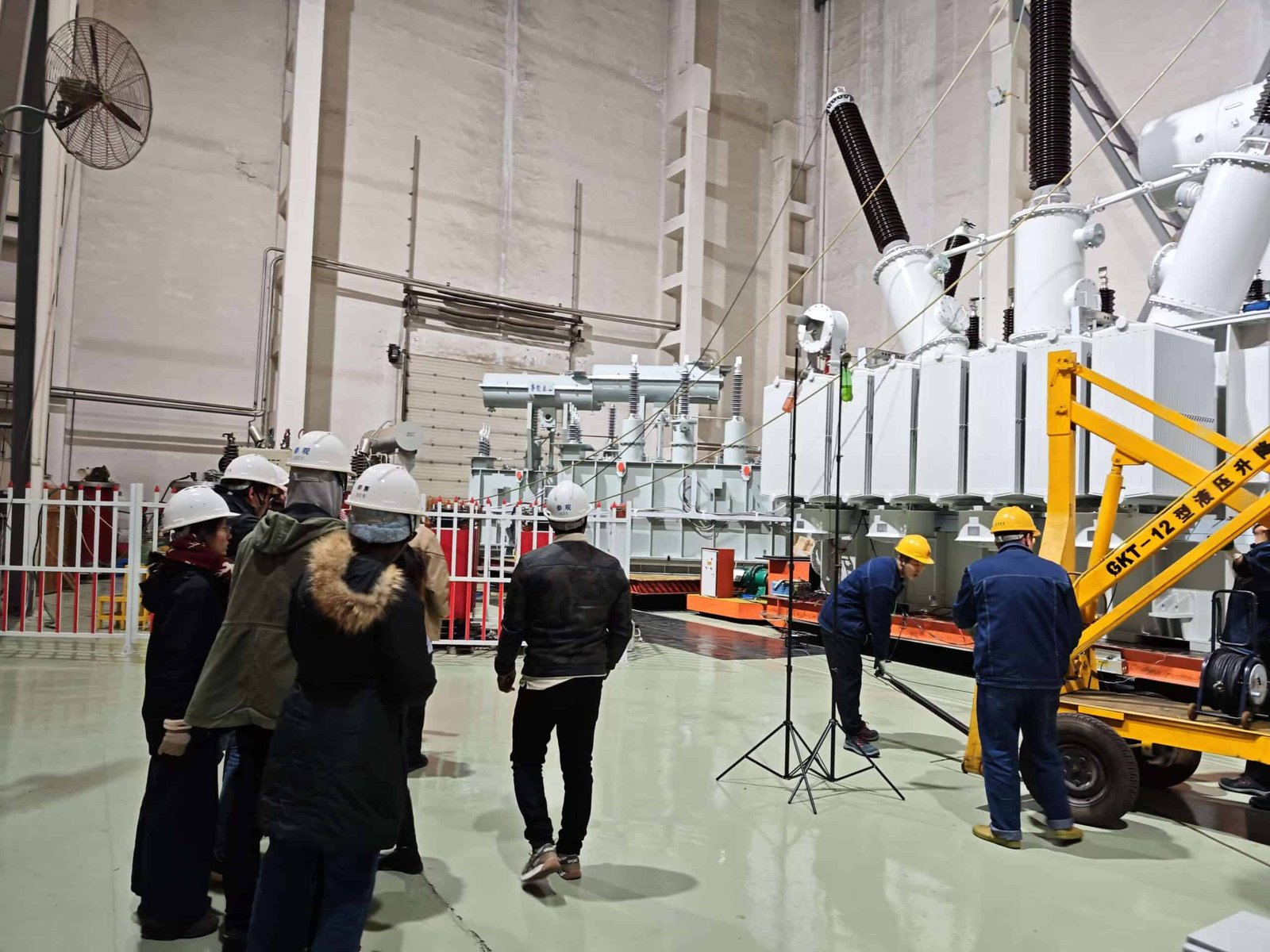
Factory Acceptance Testing (FAT) is not only a technical validation stage—it’s a collaborative milestone where customers have the right to witness, inspect, and approve the transformer before shipment. This direct participation ensures transparency, builds trust, and gives buyers confidence that the equipment meets both contractual and operational expectations.
Yes, customers can—and often are strongly encouraged to—witness or participate in the FAT process. During FAT, customer representatives can observe key electrical tests, verify measurements, inspect mechanical assemblies, ask technical questions, and approve the transformer for shipment. Virtual witnessing is also available using live video and digital dashboards when travel is not feasible.
Witnessing a FAT gives customers the opportunity to catch deviations, verify documentation, and gain hands-on understanding of the transformer before commissioning.
Customers are not allowed to witness or participate in transformer FAT.False
Customers are frequently invited to witness or participate in FAT to verify compliance, build confidence, and approve delivery readiness.
🎯 Benefits of Customer Participation in FAT
| Benefit | Description |
|---|---|
| Verification of Specifications | Confirm nameplate ratings, test parameters, and component models |
| Transparency & Trust | Direct view into manufacturing and test quality |
| Risk Reduction | Spot deviations before shipment; request corrective actions |
| Familiarization for Site Team | Engineers learn installation, wiring, and protection features |
| Legal & Warranty Protection | Witnessed results serve as binding QA documents |
🧪 What Customers Typically Witness During FAT
| Test Category | Example Tests Observed |
|---|---|
| Routine Tests | Turns ratio (TTR), winding resistance, insulation resistance |
| Type Tests (if applicable) | Temperature rise, impulse withstand, sound level |
| Control System Checks | OLTC operation, relay logic, wiring scheme |
| Protection Device Function | Buchholz relay, PRD, temperature alarms |
| Physical Inspection | Bushings, core clamping, nameplate, gaskets, paintwork |
📋 How to Prepare for FAT as a Customer
| Step | Action Item |
|---|---|
| Review FAT Protocol in Advance | Get the test plan from supplier and clarify scope |
| Assign Qualified Engineers | Choose staff with electrical background and project knowledge |
| Attend Briefing Session | Join pre-FAT orientation on test safety, sequence, and limits |
| Bring Checklists | Use standard observation forms for routine and special tests |
| Note Deviations for NCR | Document concerns and request corrections before sign-off |
🛠️ Tools Provided During FAT for Customers
| Tool or Facility | Purpose |
|---|---|
| Observation Deck | Safe, elevated view of testing floor |
| Real-Time Test Screen | Monitor voltage, current, resistance, and alarms |
| Hard Copy Test Sheets | Handwritten results for witness signature |
| Digital Report Access | PDF or dashboard summaries of each completed test |
| Translation or Technical Support | Assist international customers with standards or terms |
🌐 Virtual FAT Witnessing Options
| Feature | Description |
|---|---|
| Live Camera Feeds | Multiple angles of test benches and transformer |
| Shared Test Dashboards | Real-time readings of voltage, loss, temperature |
| Digital Sign-Off Tools | Upload feedback and approve online |
| Recorded Video Archive | Full playback for audit or review |
| Secure VPN Access (if required) | Direct login to test control systems |
💬 Customer Testimonial
“Being present for the FAT helped us clarify key installation questions and catch a small wiring mismatch in the OLTC panel. The supplier corrected it instantly. It gave us full confidence to approve shipment.”
— Utility Commissioning Manager, East Africa
Conclusion
Factory Acceptance Testing is a vital quality control step in the manufacturing of power transformers. By conducting a series of standardized and customer-specific tests, manufacturers like Luneng Taishan ensure that each unit performs reliably from the outset. A well-documented and transparent FAT process enhances trust, ensures technical compliance, and reduces risk during field commissioning and operation. For optimal outcomes, customers are encouraged to engage early and participate in FAT reviews tailored to their project’s specifications.
FAQ
Q1: What is a Factory Acceptance Test (FAT) for power transformers?
A1: A Factory Acceptance Test (FAT) is a comprehensive set of tests conducted at the manufacturing facility before shipment. It verifies that the power transformer meets design specifications, safety standards, and performance criteria as per IEC 60076 or IEEE C57.12 standards.
Q2: What are the routine tests performed during FAT?
A2: Routine tests are mandatory for each unit and include:
Winding resistance measurement
Insulation resistance and polarization index
Voltage ratio and phase displacement
Vector group verification
Short-circuit impedance and load loss
No-load loss and excitation current
Dielectric test (Applied and Induced Voltage)
Partial discharge measurement (for high voltage units)
Q3: What type tests may be included during FAT?
A3: Type tests are performed on one unit per design family, including:
Temperature rise test (heating under full load)
Lightning impulse test (BIL test)
Switching impulse test (for transformers ≥300kV)
Frequency response analysis (to check mechanical integrity)
Sound level measurement
These validate the transformer’s thermal, electrical, and mechanical performance.
Q4: Are any special tests conducted for custom or critical transformers?
A4: Special tests may be requested depending on the contract, including:
Tan delta and capacitance measurement of bushings and windings
Oil Dissolved Gas Analysis (DGA)
Core insulation test
Zero-sequence impedance test
Sweep frequency response analysis (SFRA)
These help assess design integrity, especially for large or grid-critical units.
Q5: What documents and certifications are provided after FAT?
A5: Upon successful testing, manufacturers provide:
FAT report with full test results
Test certificates (calibrated per ISO/IEC standards)
Transformer datasheet and nameplate details
Wiring diagrams and final drawings
Third-party inspection certificates, if required
Customers may witness the FAT onsite or remotely to verify compliance.
References
"IEC 60076 Transformer Testing Standards" – https://webstore.iec.ch/publication/654
"IEEE C57.12 Power Transformer Testing" – https://ieeexplore.ieee.org/document/8456762
"Energy Central: Power Transformer Testing Requirements" – https://www.energycentral.com/c/ee/transformer-factory-testing
"Hitachi Energy: FAT for Utility-Grade Transformers" – https://www.hitachienergy.com/transformer-factory-testing
"Transformers Magazine: FAT Best Practices" – https://transformers-magazine.com/factory-acceptance-tests
"Doble Engineering: Electrical Testing of Transformers" – https://www.doble.com/transformer-diagnostic-tests