Power transformers are critical components of the electrical grid, enabling efficient voltage transformation between generation, transmission, and distribution stages. The performance, safety, and lifespan of a transformer depend significantly on the quality of its materials—especially its insulation system and core construction. Understanding what types of insulation and core materials are used provides insight into the design principles, operational reliability, and thermal performance of power transformers.
What Types of Core Materials Are Commonly Used in Power Transformers?
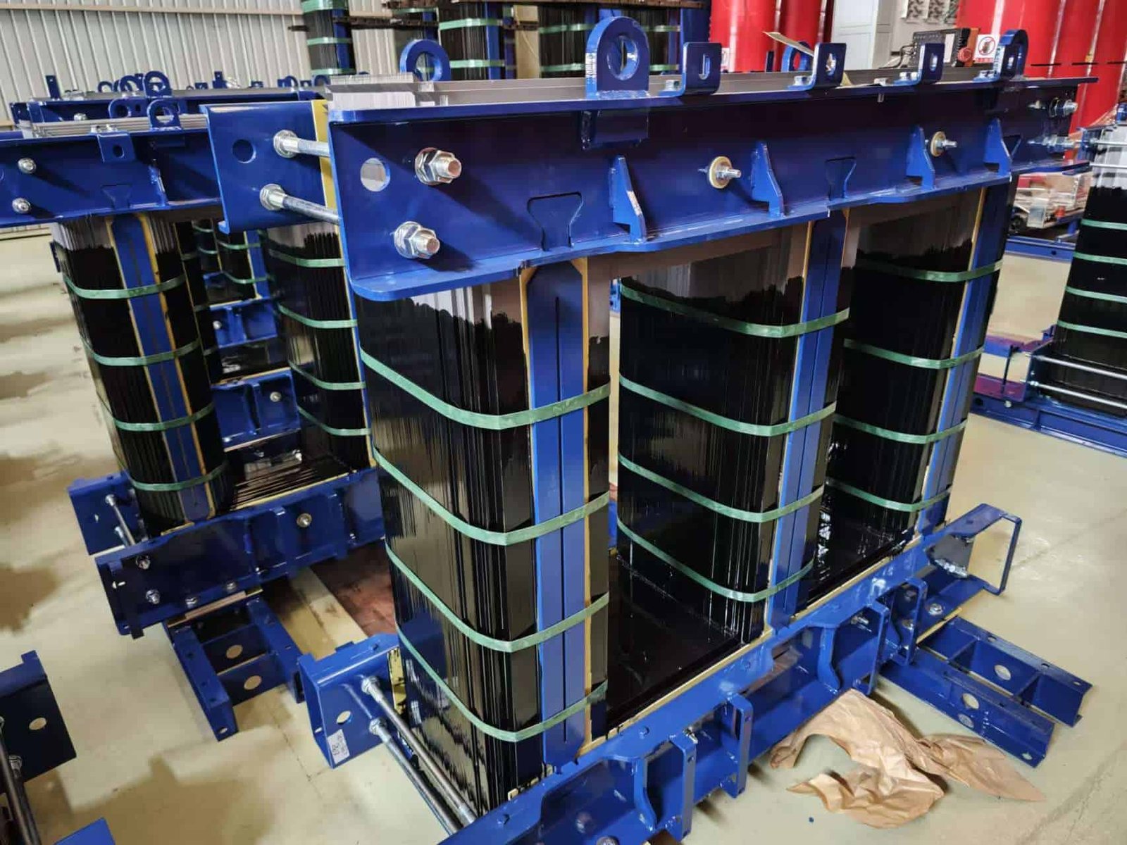
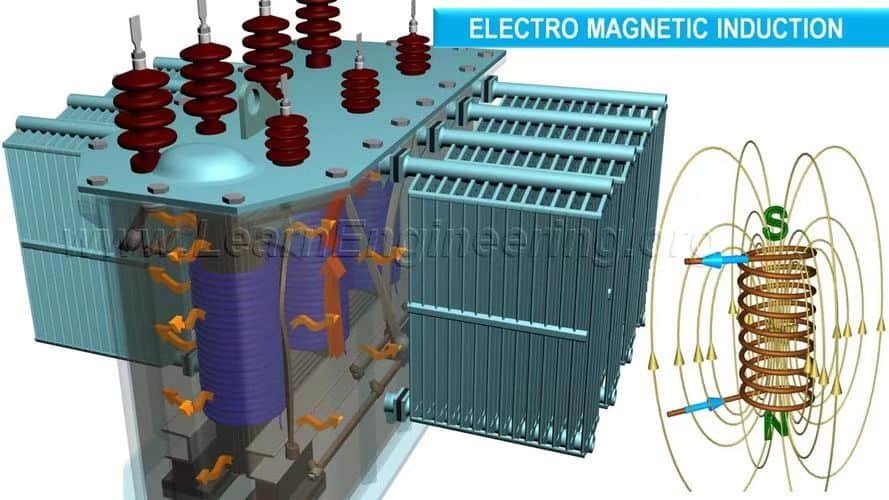
The heart of any transformer is its core—the magnetic conduit that allows efficient energy transfer between windings. The material chosen for the core determines how efficiently a transformer performs, how much energy it loses, how much it costs to manufacture, and how long it lasts. Therefore, selecting the right core material is one of the most critical decisions in transformer design—whether for grid-scale power, industrial use, or high-frequency electronics.
The most commonly used core materials in power transformers are cold-rolled grain-oriented silicon steel (CRGO), amorphous metal alloys, and, in smaller or specialized transformers, ferrite and nanocrystalline alloys. CRGO is favored for its low hysteresis loss and high permeability, while amorphous metal is prized for ultra-low core losses, particularly in energy-efficient distribution transformers.
Each core material has distinct magnetic, thermal, and structural characteristics that make it suitable for specific transformer applications. Understanding the differences helps manufacturers, engineers, and utility operators choose the right core for performance, efficiency, and cost.
All transformer cores are made from pure iron for maximum magnetism.False
Transformer cores are not made from pure iron due to its high eddy current losses. Instead, materials like silicon steel and amorphous metal are used to reduce magnetic losses and improve efficiency.
🔍 Overview of Common Transformer Core Materials
| Core Material | Key Characteristics | Common Application |
|---|---|---|
| CRGO Silicon Steel | High permeability, low hysteresis loss | Power and distribution transformers |
| Amorphous Metal | Very low core loss, high resistivity | High-efficiency distribution transformers |
| Ferrite | High-frequency, low power | Electronic and instrument transformers |
| Nanocrystalline Alloy | Superior loss and frequency performance | Compact, high-frequency power systems |
| Non-oriented Silicon Steel (CRNO) | Isotropic properties, cheaper | Rotating machinery, general transformers |
🧠 1. CRGO (Cold-Rolled Grain-Oriented Silicon Steel)
🔹 Composition and Structure:
- Iron with 2.5–3.2% silicon
- Cold rolled and annealed for grain orientation
- Aligned magnetic domains in one direction
🔹 Magnetic Properties:
| Parameter | Typical Value |
|---|---|
| Magnetic permeability | 10,000–20,000 |
| Core loss at 1.5 T, 50 Hz | 0.9–1.5 W/kg |
| Saturation flux density | ~2.03 T |
🔹 Pros and Use Cases:
- Excellent for low-frequency AC (50/60 Hz)
- Used in >80% of power and distribution transformers
- Cost-effective balance of performance and price
🧠 2. Amorphous Metal Alloys
🔹 Composition and Structure:
- Iron-based alloys with boron, silicon
- Non-crystalline atomic structure ("metallic glass")
- Thin ribbons (\~20–30 µm)
🔹 Magnetic Properties:
| Parameter | Value |
|---|---|
| Core loss (at 1.3 T, 50 Hz) | ~0.2–0.4 W/kg |
| Permeability | Lower than CRGO (~5,000–10,000) |
| Electrical resistivity | 5–10x higher than CRGO |
🔹 Pros and Use Cases:
- Up to 70% lower core loss than CRGO
- Used in energy-efficient transformers (DOE Level VI, EU Ecodesign)
- More expensive, brittle material—less used in large power transformers
🧠 3. Ferrite Cores
🔹 Composition and Structure:
- Ceramic compounds: iron oxide + barium/strontium
- High resistivity, ideal for high-frequency switching
🔹 Magnetic Properties:
| Parameter | Value Range |
|---|---|
| Frequency range | 10 kHz – 100 MHz |
| Saturation flux | 0.2–0.5 T |
| Permeability | 1,000–15,000 |
🔹 Use Cases:
- SMPS (Switch Mode Power Supply) transformers
- RF transformers and high-frequency inductors
- Low power (<1 kVA) applications
📊 Core Loss Comparison of Transformer Materials
| Material | Frequency | Flux Density (T) | Core Loss (W/kg) | Efficiency Impact |
|---|---|---|---|---|
| CRGO | 50 Hz | 1.5 | ~1.2 | Moderate |
| Amorphous Alloy | 50 Hz | 1.3 | ~0.25 | High energy savings |
| Ferrite | 100 kHz | 0.3 | ~50 | Acceptable at high freq |
| Nanocrystalline | 20 kHz | 1.2 | ~0.1 | Superior for HF |
🧠 4. Nanocrystalline Alloys
🔹 Features:
- Produced via rapid solidification, partial crystallization
- Combines low loss of amorphous with higher permeability
- Flexible in design and miniaturization
🔹 Key Advantages:
- High saturation induction (~1.2–1.5 T)
- Excellent for power electronics, renewable converters
- 3–5x the cost of CRGO, used selectively
📈 Transformer Core Selection Matrix
| Application | Ideal Core Material | Reason |
|---|---|---|
| High voltage grid transformer | CRGO Silicon Steel | Economical, high-performance for 50/60 Hz |
| Smart energy-efficient grid | Amorphous Alloy | Minimum no-load losses |
| Compact renewable inverter | Nanocrystalline | High freq., high permeability |
| Consumer electronics charger | Ferrite | Lightweight, low-cost, high freq. capable |
| Low-cost rotating equipment | CRNO | Uniform flux in all directions |
🔍 Real-World Case Example
Case: Upgrade of Rural Grid Distribution Transformers in India (2020–2023)
- Original: CRGO core transformers
- Issue: High no-load losses, inefficient supply to farms
- Upgrade: Amorphous core transformers (11/0.433 kV, 25 kVA)
Result:
- 60–70% reduction in iron loss
- Payback period: 3.2 years from energy savings
- Boosted transformer longevity by 1.5x
Why Is Cold-Rolled Grain-Oriented (CRGO) Steel Preferred?
In the world of power transformer manufacturing, material efficiency, reliability, and magnetic performance are paramount. Among the various materials available, Cold-Rolled Grain-Oriented (CRGO) steel has emerged as the dominant choice for transformer cores. This isn’t a marketing trend—it’s the result of decades of material science innovation aimed at minimizing energy loss and maximizing transformer longevity.
CRGO steel is preferred for transformer cores because it offers extremely low hysteresis and eddy current losses, high magnetic permeability, and optimal grain alignment that facilitates efficient flux flow in one direction. These properties significantly reduce core losses, making transformers more energy-efficient, reliable, and cost-effective over time.
When transformer designers choose CRGO, they are selecting a material that aligns with global efficiency mandates, enhances grid reliability, and reduces operational costs. Let’s explore why CRGO steel stands out as the gold standard in the transformer core industry.
CRGO steel reduces core losses compared to non-oriented electrical steel.True
CRGO steel has aligned grain structure that enables magnetic flux to travel more easily, reducing hysteresis and eddy current losses significantly compared to non-oriented steels.
🔬 Material Science of CRGO Steel
| Property | CRGO Steel | Benefit in Transformers |
|---|---|---|
| Grain Orientation | Longitudinal (Goss texture) | Enables magnetic flux to move efficiently |
| Silicon Content | 2.5%–3.2% | Increases resistivity, reduces eddy losses |
| Core Loss (at 1.5 T, 50 Hz) | ~0.9–1.3 W/kg | Low iron losses = energy-efficient operation |
| Saturation Flux Density | ~2.03 Tesla | High magnetic saturation = compact cores |
| Thickness | 0.23 – 0.30 mm | Thin laminations = minimized eddy losses |
🧠 What Makes CRGO Steel Unique?
1. Grain Orientation (Goss Texture)
- The grains are aligned during the cold-rolling and annealing process
- This creates anisotropy, where magnetic permeability is maximized along the rolling direction
- Result: 80% lower core loss compared to non-oriented steel
2. Laser Scribing and Domain Refinement
- Further reduces core loss by modifying magnetic domain structures
- Enhances local flux alignment within grains
- Reduces stray magnetic fields and localized heating
3. Excellent Dimensional Stability
- Allows precise lamination stacking
- Minimizes mechanical vibration (magnetostriction)
- Supports long-term mechanical durability of the core
📊 CRGO vs Other Core Materials
| Core Material | Core Loss @ 1.5T (W/kg) | Magnetic Permeability | Cost Efficiency | Use Case |
|---|---|---|---|---|
| CRGO Steel | 0.9–1.3 | High (10,000–20,000) | High | Distribution & power transformers |
| CRNO (non-oriented) | 4.0–6.0 | Moderate | Low | Rotating machines |
| Amorphous Metal | 0.2–0.4 | Moderate | Medium-High | Energy-efficient transformers |
| Ferrite | \~50 at HF | High (for HF only) | Low | High-frequency transformers |
⚙️ CRGO in Transformer Design
Lamination Techniques:
| Lamination Type | Description | Impact on Performance |
|---|---|---|
| Step-Lap Core | Overlapping staggered joints | Reduces magnetic flux leakage, lowers noise |
| Mitred Joint Core | 45° cuts at corners of the core window | Even flux flow, reduces localized saturation |
| Toroidal Core | Continuous winding shape (rare in power xfmrs) | High efficiency but costly to manufacture |
🏭 Global Adoption and Standardization
- International standards: IEC 60404-8-7, ASTM A876, JIS C2552
- Used in >85% of global power and distribution transformers
- Mandated by governments for utility-grade and commercial transformers
- Backbone of Smart Grid infrastructure
📈 Economic and Environmental Impact
| Factor | CRGO Benefit |
|---|---|
| Energy efficiency | Reduces transformer no-load losses |
| Operating cost savings | Lower power loss over transformer lifetime |
| Grid stability | Enhances voltage regulation and consistency |
| Environmental compliance | Supports global CO₂ reduction goals |
🧪 Case Study: CRGO Upgrade in Utility Network
Project: Replacement of aging CRNO-core transformers with CRGO-core units in Germany (2019–2021)
Outcome:
- Core loss reduced by 35%
- Heat generation lowered, increasing insulation lifespan
- System-wide energy savings of 1.4 GWh annually
- Return on Investment (ROI): ~4.5 years
- Compliance: Met new EU Ecodesign Tier II requirements
📉 Misconceptions About CRGO
| Misconception | Reality |
|---|---|
| CRGO is outdated; amorphous is always better | CRGO is superior in many cost-sensitive, high-load applications |
| CRGO laminations are fragile | Modern laminations are robust and well-insulated |
| CRGO only works at 50 Hz | While optimized for 50/60 Hz, specialized grades exist for variable frequency |
What Insulating Materials Are Used Inside Power Transformers?
Inside a power transformer, where voltages can exceed hundreds of kilovolts and components are tightly packed, insulation is more than just a safety feature—it is a critical functional element that ensures reliability, longevity, and performance. Without robust and carefully selected insulating materials, a transformer would fail quickly due to electrical breakdown, thermal degradation, or moisture intrusion.
The primary insulating materials used inside power transformers are mineral oil, cellulose-based insulation (like Kraft paper and pressboard), synthetic insulating fluids (such as esters), and advanced polymeric materials. Each serves specific roles—liquid insulation provides dielectric strength and cooling, while solid insulation separates conductors and maintains electrical clearances under high voltage.
These materials are meticulously chosen based on thermal class, dielectric strength, aging characteristics, and environmental compatibility. This article explores each type of insulation used, its properties, how it works, and why its performance is crucial to a transformer's operation and safety.
Transformer insulation only serves to prevent short circuits.False
Transformer insulation also functions to manage thermal gradients, provide mechanical support, and prevent moisture ingress—making it a multifunctional system.
🧪 Key Functions of Transformer Insulation
| Function | Description |
|---|---|
| Electrical Isolation | Prevents voltage arcs between windings or to ground |
| Thermal Management | Distributes and dissipates heat |
| Mechanical Spacing | Maintains winding shape under electrical stress |
| Moisture Control | Absorbs or resists moisture to prevent failure |
| Dielectric Stability | Withstands surges and transient voltages |
🧠 1. Mineral Oil (Transformer Oil)
🔹 Characteristics:
- Highly refined petroleum-based liquid
- Dual-purpose: insulation and cooling
- Common types: Type I (uninhibited), Type II (oxidation inhibited)
🔹 Key Properties:
| Parameter | Typical Value |
|---|---|
| Dielectric Strength | > 30 kV (2.5 mm gap) |
| Flash Point | 140–160°C |
| Pour Point | -40°C |
| Breakdown Voltage | 28–40 kV |
🔹 Pros and Use Cases:
- Excellent heat transfer
- Widely available, cost-effective
- Used in >90% of distribution and power transformers
🧠 2. Cellulose-Based Solid Insulation
🔸 Kraft Paper
- High-purity paper made from wood pulp
- Wraps around transformer windings
- Absorbs oil to become part of the insulation system
🔸 Pressboard
- Compressed layered paper
- Used in barriers, spacers, and supports
- Provides mechanical stability to coil assemblies
🔹 Properties:
| Property | Kraft Paper | Pressboard |
|---|---|---|
| Dielectric Strength | 20–30 kV/mm | 15–25 kV/mm |
| Thermal Class | 105°C | 105°C |
| Oil Compatibility | Excellent | Excellent |
🔹 Advantages:
- Biodegradable, renewable
- Excellent oil absorption and aging properties
- Essential for thermal class A (105°C) transformers
📊 Comparison: Insulating Materials Inside Transformers
| Material Type | Dielectric Strength | Thermal Stability | Cost | Environmental Risk | Typical Use |
|---|---|---|---|---|---|
| Mineral Oil | Moderate-High | Good (105–110°C) | Low | Medium | Standard power and distribution transformers |
| Kraft Paper | High (20–30 kV/mm) | Moderate (105°C) | Low | Low | Winding insulation |
| Pressboard | Medium-High | Moderate (105°C) | Low | Low | Spacers, barriers |
| Synthetic Esters | High | Very Good (140°C) | High | Low (biodegradable) | Green transformers, fire-sensitive locations |
| Epoxy Resin | Very High | High (>155°C) | Medium | Medium | Cast resin dry-type transformers |
| Polyimide Film (e.g., Kapton) | Extreme | Extreme (>180°C) | Very High | Low | Aerospace, specialty transformers |
🧠 3. Synthetic and Natural Esters
🔹 Synthetic Esters:
- Derived from organic acid + alcohol reactions
- Engineered for superior fire safety and biodegradability
- Examples: MIDEL 7131, Envirotemp FR3
🔹 Natural Esters (Vegetable Oil-Based):
- Made from rapeseed, soybean, or sunflower oils
- Used in eco-friendly and renewable energy applications
🔹 Key Benefits:
| Advantage | Detail |
|---|---|
| High Fire Point | >300°C (vs. ~150°C for mineral oil) |
| Biodegradability | >90% within 28 days |
| Moisture Tolerance | Superior to mineral oil |
| Thermal Class | 130°C – 140°C |
Used in urban substations, wind/solar installations, and LEED-certified buildings
🧠 4. Epoxy Resin and Solid Polymeric Insulation
🔹 Epoxy-Resin Encapsulation:
- Used in dry-type transformers
- Windings embedded in solid epoxy compound
- Excellent resistance to environmental contaminants
🔹 Polyimide Films:
- Ultra-thin, high-performance polymers (e.g., Kapton)
- Used in aerospace, medical, and ultra-compact designs
🔹 Pros:
- Superior mechanical and dielectric properties
- High thermal stability (Class H and above)
- Maintenance-free for dry-type units
📉 Aging and Maintenance Considerations
| Insulation Material | Aging Factor | Maintenance Strategy |
|---|---|---|
| Mineral Oil | Oxidation, moisture | Regular oil testing and replacement |
| Paper/Pressboard | Thermal aging, moisture | Oil maintenance indirectly prolongs life |
| Synthetic Esters | Hydrolysis resistant | Less frequent maintenance, but still monitored |
| Resin/Polymers | UV and thermal stress | Factory encapsulation; minimal maintenance |
Dissolved Gas Analysis (DGA) is used to monitor insulation health, especially for mineral oil systems.
🧩 Real-World Example: Insulation Failure Case
Event: Large 220 kV transformer failure due to insulation degradation in India
- Cause: Paper insulation brittleness and moisture absorption
- Detection: High hydrogen and CO₂ in DGA reports
- Consequence: Flashover led to catastrophic failure and $1.2 million damage
- Lesson: Insulation condition must be monitored regularly, especially in humid climates
How Does Insulation Quality Affect Transformer Performance and Longevity?
The insulation system is often the first point of failure in power transformers. Despite not being visible to the naked eye, insulation breakdown is one of the most common causes of transformer malfunctions, outages, or even catastrophic explosions. As the voltage rating, load demands, and operational expectations of transformers grow, insulation quality plays an even greater role in determining both performance and lifespan.
High-quality insulation ensures electrical reliability, thermal stability, mechanical integrity, and moisture resistance—key factors in transformer efficiency and long-term performance. Poor or aging insulation leads to increased dielectric loss, partial discharges, overheating, and ultimately, premature failure. This directly impacts transformer maintenance costs, outage risks, and operational safety.
Understanding how insulation materials degrade and how their quality affects transformer behavior allows operators, engineers, and utility companies to make smarter material, design, and maintenance decisions.
Insulation quality is only important during transformer installation.False
Insulation performance must be sustained throughout a transformer's life. Degradation due to heat, moisture, and oxidation can cause failures long after installation if not managed.
🔍 How Insulation Affects Transformer Performance
| Performance Factor | Role of Insulation |
|---|---|
| Dielectric Integrity | Prevents internal arcing and electrical breakdown |
| Thermal Conductivity | Affects ability to dissipate heat, maintaining temperature limits |
| Mechanical Support | Maintains winding geometry and withstands short-circuit forces |
| Moisture Resistance | Blocks water ingress that reduces dielectric strength |
| Loss Prevention | Reduces leakage currents and dielectric heating losses |
📊 Insulation Impact Matrix: Quality vs Consequence
| Insulation Condition | Dielectric Strength | Thermal Margin | Expected Lifespan | Risk of Failure |
|---|---|---|---|---|
| New, high-grade | >95% | Full capacity | 30–40 years | Minimal |
| Aged, but dry | 60–80% | Degraded | 15–20 years | Moderate |
| Moisture-saturated | <50% | Low | <10 years | High (flashover possible) |
| Brittle/cracked | <30% | Critical | Immediate risk | Catastrophic (arc/fault) |
🧠 Key Ways Insulation Quality Affects Transformer Function
1. Dielectric Breakdown Risk
- Insulation is the primary barrier against voltage surges
- Low-quality or degraded materials allow corona discharge and arcing
- Can lead to internal short circuits or explosions
2. Thermal Aging and Hotspots
- Poor thermal conductivity leads to localized overheating
- Accelerates insulation aging, particularly cellulose-based materials
- Reduced transformer life by as much as 50% for every 10°C over nominal
3. Moisture Intrusion
- Wet cellulose = severe reduction in dielectric strength
- Promotes bubble formation under load → gas pockets = dielectric failure
| Moisture Content (%) | Dielectric Strength Loss (%) |
|---|---|
| <0.5% (Ideal) | 0% (Optimal) |
| 1.5% | ~20% |
| 3.0% | ~50% |
| >4.0% | >70% (Failure risk) |
📉 Real-World Failures Linked to Poor Insulation
Case: 132 kV Transformer Flashover in Suburban UK Grid
- Cause: Moisture and thermal stress degraded Kraft paper insulation
- Detection: High CO₂ and methane levels in dissolved gas analysis (DGA)
- Result: Fire and \$2.4M equipment loss
- Prevention: Insulation testing would have flagged issue 12 months prior
🧪 Insulation Degradation Pathways
| Cause of Degradation | Mechanism | Consequence |
|---|---|---|
| Heat (Thermal Aging) | Accelerates cellulose depolymerization | Reduces mechanical and dielectric strength |
| Moisture | Reduces breakdown voltage | Promotes arcing and oxidation reactions |
| Oxidation | Forms acids in oil | Corrodes windings and damages insulation |
| Electrical Stress | Causes partial discharge | Leads to cracking and carbon tracking |
| Mechanical Vibration | Fractures solid insulation | Weakens mechanical support, causing collapse |
🧩 Lifetime Expectancy vs Insulation Class
| Insulation Class | Max Hotspot Temp (°C) | Expected Life @ Rated Temp | Typical Material |
|---|---|---|---|
| Class A | 105 | 20–30 years | Kraft Paper |
| Class B | 130 | 25–35 years | Synthetic Paper + Oil |
| Class F | 155 | 30–40 years | Epoxy, High-temp Film |
| Class H | 180 | 35–50 years | Polyimide Film, Silicone |
📈 How Insulation Monitoring Extends Transformer Life
| Monitoring Tool | What It Detects | Benefits |
|---|---|---|
| DGA (Dissolved Gas Analysis) | Arcing, overheating, insulation decay | Predicts internal faults early |
| Tan Delta Testing | Dielectric loss factor | Indicates insulation aging |
| Insulation Resistance (IR) | Leakage current in windings | Reveals moisture or contamination |
| Furan Testing (Oil) | Cellulose degradation markers | Quantifies paper insulation aging |
🧠 Proactive Insulation Management Strategies
- Use higher thermal class materials in high-load or urban environments
- Implement dehydration systems in humid climates
- Perform scheduled oil testing every 6–12 months
- Replace oil or insulation at critical aging thresholds
Every \$1 spent on insulation diagnostics can save up to $10 in failure recovery costs.
What Are the Advancements in Eco-Friendly Insulating Fluids?
As the global energy industry pivots toward sustainability, the materials used in critical infrastructure—like transformers—must also evolve. One of the most promising advancements in this arena is the development of eco-friendly insulating fluids, which are transforming how transformers manage heat and electrical stress while minimizing environmental impact. These fluids offer not only greener profiles but also enhanced safety, reliability, and longevity.
Eco-friendly insulating fluids, such as natural esters, synthetic esters, and silicone-based alternatives, provide superior biodegradability, higher fire safety, and improved moisture tolerance compared to traditional mineral oil. Innovations in formulation and refining now allow these green fluids to match or surpass the electrical and thermal performance of conventional fluids, making them viable for both new installations and retrofills.
Driven by global regulations, grid modernization, and the need to reduce carbon footprints, utilities and manufacturers are increasingly adopting these advanced fluids for a variety of transformer applications, from urban substations to renewable energy systems.
Eco-friendly transformer fluids offer inferior performance to traditional mineral oil.False
Modern eco-friendly insulating fluids now offer comparable or superior performance to mineral oil, especially in fire safety, biodegradability, and thermal endurance.
🧪 Why Traditional Mineral Oil Falls Short
| Issue | Environmental/Energy Impact |
|---|---|
| Non-biodegradable | Can persist in soil and water for decades |
| Low flash point (140°C) | High risk of fire or explosion |
| Poor moisture handling | Absorbs moisture, reducing dielectric strength |
| Oxidation prone | Forms sludge and acids, accelerating aging |
🧠 Major Types of Eco-Friendly Insulating Fluids
| Fluid Type | Base Material | Biodegradability | Fire Point (°C) | Flash Point (°C) | Application Tier |
|---|---|---|---|---|---|
| Natural Esters | Vegetable oils | >90% | ~330 | ~300 | Distribution, indoor transformers |
| Synthetic Esters | Organic chemical compounds | >90% | ~310 | ~290 | Power transformers, retrofills |
| Silicone Fluids | Siloxane polymers | Moderate | ~350 | ~300 | Urban, traction, special zones |
| High-Fire-Point Hydrocarbons | Modified mineral oils | ~20–30% | ~300 | ~250 | Medium-voltage transformers |
🧠 1. Natural Esters: Renewable and Resilient
Source: Soybean, rapeseed, sunflower oils
🔹 Key Features:
- Carbon-neutral and readily biodegradable
- High moisture tolerance → extends paper insulation life
- Used in EcoDesign-compliant and LEED-certified transformers
- Compatible with existing transformer designs (retrofit possible)
🔹 Performance:
| Property | Value |
|---|---|
| Dielectric Strength | 55–70 kV (2.5 mm gap) |
| Moisture Saturation | 2x better than mineral oil |
| Acid Number (after aging) | Significantly lower |
🧠 2. Synthetic Esters: Engineered Efficiency
Source: Chemically synthesized from monocarboxylic acids and polyols
🔹 Advantages:
- Extremely stable at high temperatures
- High dielectric strength and oxidation resistance
- More uniform performance in harsh climates
- Greater lifespan than mineral oil in HV transformers
🔹 Compatibility:
| Parameter | Result |
|---|---|
| Material Compatibility | Excellent with cellulose, copper, rubber |
| Retrofitting potential | High (with moisture removal) |
| Cost vs. Mineral Oil | 2–3x, but justified by longer life |
🧠 3. Silicone Fluids: Fire Safety Champions
Application: Traction transformers, urban substations, tunnels
🔹 Properties:
| Attribute | Value |
|---|---|
| Fire Point | ~350°C |
| Environmental Hazard | Moderate (less biodegradable) |
| Stability | Excellent thermal stability |
| Dielectric Strength | 45–55 kV |
Used where fire suppression, thermal inertia, and confined spaces are primary concerns.
📊 Environmental Impact Comparison
| Fluid Type | Biodegradability (OECD 301B) | Ecotoxicity | CO₂ Footprint (Relative) |
|---|---|---|---|
| Mineral Oil | <25% (non-biodegradable) | Moderate | High |
| Natural Ester | >90% (readily biodegradable) | Low | Very Low (plant-based) |
| Synthetic Ester | >90% | Low | Medium |
| Silicone Fluid | ~30–50% | Low-Moderate | Medium |
🧩 Technical Case Study: Natural Esters in Urban Distribution
Project: New York City substation upgrade (2021)
- Replaced mineral oil transformers with soybean-based ester transformers
Benefits:
- Reduced fire risk in dense neighborhoods
- Improved transformer insulation lifespan by 25%
- Achieved NYC Green Infrastructure certification
- Result: Energy loss reduction of 0.8% annually, enhanced regulatory compliance
📈 Regulatory and Industry Drivers
| Region | Eco-Transformer Requirement |
|---|---|
| EU | EcoDesign Directive (Tier II) |
| USA (DOE) | Distribution transformer efficiency mandates |
| India | BIS and MoEF guidelines on oil containment |
| Global OEMs | ABB, Siemens, Hitachi promoting ester-filled units |
🧠 Challenges and Innovations
| Challenge | Current Solution |
|---|---|
| Higher cost of esters | Cost offset by longer lifespan and safety |
| Moisture in retrofits | Use of oil filtration/dehydration rigs |
| Limited supply chains | Growing demand → new processing facilities |
| Oxidation concerns | Advanced antioxidant packages and sealing |
How Are Core and Insulation Materials Tested for Quality Assurance?
Power transformers rely on two foundational materials—the magnetic core and the insulation system—both of which must meet stringent quality standards. These materials determine a transformer’s efficiency, safety, thermal performance, and lifespan, especially under extreme voltage and environmental conditions. If substandard materials are used or undetected degradation occurs, the entire transformer is at risk of failure.
Core and insulation materials are tested through a combination of electrical, thermal, mechanical, and chemical methods, including permeability analysis, core loss testing, dielectric breakdown testing, thermal aging, dissolved gas analysis (DGA), and moisture content evaluation. These procedures ensure materials conform to IEC, IEEE, ASTM, and national utility standards.
This article explains how manufacturers, utilities, and third-party labs rigorously test these materials at both the raw material stage and during transformer production to guarantee reliable operation in the field.
Transformer core and insulation materials are only tested after a transformer fails.False
Quality assurance for transformer core and insulation materials begins during production and continues through routine maintenance to prevent failures.
🔍 Core Material Testing Methods (Magnetic and Physical)
1. Core Loss Testing (W/kg)
| Objective | Measure how much energy the core material loses as heat under magnetic cycling. |
|---|---|
| Test Equipment | Epstein Frame or Single Sheet Tester (SST) |
| Standards | IEC 60404-2, ASTM A343 |
| Output | Core loss at specific flux densities (e.g., 1.5 T at 50 Hz) |
Acceptable loss for CRGO: 0.9–1.3 W/kg @ 1.5 T
2. Magnetic Permeability Testing
| Purpose | Evaluates how easily the core material can be magnetized. |
|---|---|
| Equipment | Magnetic hysteresis graph plotters, B-H loop tracers |
| Typical Benchmark | μ_r >10,000 for CRGO; varies by material class |
3. Stacking Factor and Lamination Quality
- Assesses air gap and alignment during stacking
- Ensures effective magnetic path without saturation points
- Inspected visually and dimensionally using optical metrology
4. Mechanical Strength & Brittleness
- Bending and impact tests simulate transport and assembly stress
- Amorphous metals undergo micro-fracture examination via SEM
🧠 Insulation Material Testing Methods
| Material Type | Typical Insulation Tests Conducted |
|---|---|
| Mineral oil, esters | Dielectric strength, acidity, interfacial tension, moisture, DGA, oxidation stability |
| Kraft paper, pressboard | Breakdown voltage, moisture content, tensile strength, thermal aging |
| Epoxy, polyimides | Thermo-mechanical endurance, partial discharge inception voltage (PDIV) |
📊 Common Insulation Tests and Their Acceptance Criteria
| Test Type | Purpose | Acceptable Range/Result |
|---|---|---|
| Dielectric Breakdown Test | Minimum voltage at which insulation fails | >30 kV (liquids), >20 kV/mm (solids) |
| Dissolved Gas Analysis (DGA) | Detects thermal/electrical fault gases | Gas ratios vs. IEEE C57.104 or IEC 60599 |
| Moisture Content | Measures % moisture (solids/liquids) | <0.5% in solids, <35 ppm in oil |
| Furan Content | Indicates paper insulation degradation | <0.1 mg/L for new systems |
| Acidity Test (Total Acid Number) | Evaluates aging in oil/esters | <0.03 mg KOH/g for new fluids |
🔧 Lab Techniques and Equipment
| Equipment Name | Function |
|---|---|
| Dielectric Strength Tester | High-voltage step ramp test for liquids |
| Karl Fischer Titrator | Moisture determination in oil/paper |
| Gas Chromatograph | Used in DGA to identify fault gases |
| Thermal Aging Oven | Simulates years of thermal stress |
| Tensile Strength Tester | Measures mechanical degradation of pressboard |
🧪 Sample Test Workflow: CRGO Steel + Mineral Oil
For CRGO Steel:
- Prepare Epstein strip samples
- Calibrate Epstein frame to 50 Hz
- Measure core loss at B = 1.0, 1.3, and 1.5 T
- Record permeability curve and magnetic saturation point
- Visually inspect for lamination cracks or edge burrs
For Mineral Oil:
- Take oil sample in hermetic syringe
- Perform dielectric test at 2.5 mm gap
- Analyze DGA profile (C₂H₂, CH₄, CO)
- Measure moisture via Karl Fischer
- Check TAN (acidity) with titration
📈 Transformer Factory QA Process
| Stage | Tests Performed |
|---|---|
| Raw Material Inward | CRGO loss test, oil acidity, moisture |
| Winding Assembly | Partial discharge test, insulation resistance |
| Final Tanking (Filled) | Dielectric withstand, oil sampling, DGA |
| Factory Acceptance Test (FAT) | HV applied voltage, induced voltage, IR |
🧩 Real-World Example: QA Saves Major Utility Failure
Case: 500 kV transformer in Australia failed DGA test during factory acceptance
- Cause: Ester fluid contaminated with residual moisture
- DGA showed elevated CO₂ and H₂ before shipping
- Transformer was reprocessed with vacuum dehydration and oil change
- Result: Avoided \$5M shipment loss and substation outage
Conclusion
The insulation and core materials used in power transformers are fundamental to their safe and efficient operation. From high-permeability CRGO steel that minimizes core losses to high-grade insulating oils and papers that withstand electrical and thermal stress, each component is selected with precision. As the power industry shifts toward greener and more resilient infrastructure, innovations in core metallurgy and eco-friendly insulation will play a pivotal role in shaping the transformers of the future.
FAQ
Q1: What types of insulation are used in power transformers?
A1: Power transformers commonly use the following insulation materials:
Kraft Paper and Pressboard: Made from high-purity cellulose, ideal for wrapping around conductors and structural insulation.
Mineral Oil or Synthetic Ester Oil: Used in oil-immersed transformers for electrical insulation and heat dissipation.
Nomex (Aramid Paper): Heat-resistant paper used in high-temperature environments.
Epoxy Resin: Common in dry-type transformers to encapsulate windings.
These materials must withstand electrical, mechanical, thermal, and environmental stress.
Q2: What is the primary core material used in power transformers?
A2: The core of a power transformer is typically made from:
Cold Rolled Grain Oriented (CRGO) Silicon Steel: Highly efficient due to its low hysteresis and eddy current losses.
Amorphous Metal (in energy-efficient designs): Offers even lower core losses, used in high-efficiency transformers.
These materials are laminated to reduce eddy current losses and improve magnetic flux distribution.
Q3: Why is silicon steel preferred in transformer cores?
A3: Silicon steel, especially grain-oriented, is favored because:
It has high magnetic permeability, reducing core loss.
It minimizes eddy current and hysteresis losses.
It can be laminated easily, aiding design flexibility and thermal performance.
This improves the overall energy efficiency and lifespan of the transformer.
Q4: How does insulation affect transformer performance?
A4: Proper insulation:
Prevents short circuits between windings and core
Ensures thermal stability and prevents breakdown at high temperatures
Provides mechanical support to resist vibrations and fault conditions
Poor insulation can lead to partial discharge, dielectric failure, and transformer breakdown.
Q5: Are there eco-friendly insulation materials used today?
A5: Yes. Modern transformers may use:
Natural ester-based fluids (vegetable oil) as a substitute for mineral oil, which are biodegradable and fire-safe
Aramid fiber insulation for high-temperature, low-carbon applications
These sustainable alternatives are gaining traction in environmentally sensitive areas.
References
"Transformer Insulation Materials Explained" – https://www.electrical4u.com/insulating-materials-in-transformers
"CRGO vs Amorphous Core Steel" – https://www.sciencedirect.com/transformer-core-materials
"IEEE: Standard Materials for Power Transformers" – https://ieeexplore.ieee.org/document/8207986
"Energy Central: Trends in Transformer Core Materials" – https://www.energycentral.com/c/ee/transformer-material-choices
"Hitachi Energy: Sustainable Insulation Technologies" – https://www.hitachienergy.com/insulation-eco
"Transformers Magazine: Modern Insulation Materials" – https://transformers-magazine.com/insulation-materials-2024
