Power transformers are critical components in power systems, and their procurement involves detailed engineering, specialized manufacturing, and logistical planning. The delivery schedule for a power transformer is a vital factor in project timelines for substations, grid expansion, and industrial infrastructure. Understanding the typical lead time—from technical specification to site delivery—helps stakeholders manage expectations and coordinate resources more effectively.
What Are the Key Stages in the Manufacturing of a Power Transformer?
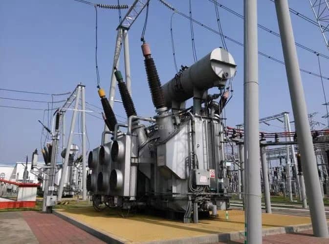
The power transformer is the cornerstone of modern electrical infrastructure, and its manufacture demands a precise blend of material science, mechanical engineering, and electrical design. From energy-efficient amorphous cores to high-temperature insulation systems, each production stage must adhere to strict tolerances and quality control standards to ensure reliability under high voltage and long service life.
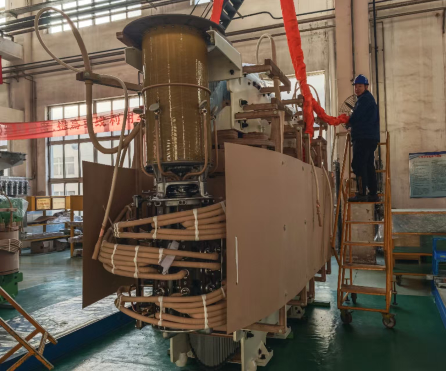
The manufacturing of a power transformer involves sequential stages including core assembly, coil winding, insulation placement, core-coil assembly, tank fabrication, oil filling, and rigorous electrical testing. Each step is governed by ISO and IEC standards, using precision machinery and strict quality controls to ensure the final product meets performance and durability specifications.
Understanding these steps not only highlights the engineering precision involved but also helps stakeholders evaluate supplier capabilities and ensure procurement of high-quality units.
Power transformers are manufactured in a single assembly process without distinct stages.False
Transformer manufacturing involves multiple interdependent stages including core construction, coil winding, insulation, tanking, and testing, each critical for quality assurance.
🛠️ Step 1: Design & Engineering
| Activity | Description |
|---|---|
| Load & Voltage Analysis | Determines turns ratio, insulation class, cooling type |
| Thermal & Magnetic Design | Establishes core type (CRGO/amorphous), B-H curve design |
| CAD & FEM Simulations | Validates flux distribution, leakage reactance |
| Compliance Standards | IEC, IEEE, NEMA, or customer-specific specifications |
Design leads to a custom blueprint defining every mechanical, electrical, and dimensional parameter.
🧲 Step 2: Core Cutting & Assembly
| Task | Description |
|---|---|
| Lamination Selection | CRGO or amorphous metal sheets |
| Cutting & Slitting | CNC precision shearing of laminations to exact lengths |
| Stacking | Step-lap or mitered stack assembly to reduce flux leakage |
| Clamping & Insulation | Epoxy-coated or varnish-insulated sheets with magnetic flux equalization |
Core loss testing and air gap verification follow.
🔁 Step 3: Coil Winding
| Coil Type | Details |
|---|---|
| Low Voltage (LV) | Thicker conductors, often strip or rectangular |
| High Voltage (HV) | Multi-layer round wire or foil for impulse endurance |
| Material | Copper or aluminum, based on cost-efficiency analysis |
- Computerized coil winding machines ensure tight tolerances
- Inter-turn insulation is inserted during winding
🔋 Step 4: Insulation and Drying
| Material Used | Function |
|---|---|
| Kraft Paper | Inter-layer dielectric barrier |
| Pressboard | Mechanical strength and dielectric isolation |
| Epoxy/Polyester Resins | Enhance partial discharge (PD) resistance |
| Drying Process | Vacuum drying oven removes moisture from insulation |
Moisture content is reduced to <0.5%, preventing premature aging.
🔗 Step 5: Core-Coil Assembly
| Step | Description |
|---|---|
| Positioning | HV and LV coils mounted concentrically on limb cores |
| Bracing & Clamping | Mechanical support against electromagnetic forces |
| Lead Connections | Insulated bushings, tap changers connected |
| Clearance Inspection | Ensures dielectric distances meet BIL requirements |
Partial discharge test often conducted before tanking.
🛢️ Step 6: Tank Fabrication & Assembly
| Component | Process |
|---|---|
| Steel Tank | Welded and pressure tested |
| Radiators & Conservator | Attached for cooling and oil expansion |
| Bushing Mounts | CNC cutouts for precision fitting |
| Painting | Epoxy powder or hot-dip galvanized finish for corrosion resistance |
Final structure passes hydrostatic leak test.
🧪 Step 7: Oil Filling and Degassing
| Fluid Type | Purpose |
|---|---|
| Mineral Oil or Ester Fluid | Cooling and dielectric insulation |
| Degassing Process | Vacuum dehydration to remove dissolved gases |
| Filling Conditions | Conducted under vacuum to avoid moisture contamination |
Oil is sampled for DGA, acidity, and breakdown voltage testing.
🔌 Step 8: Final Electrical Testing
| Test | Standard | Purpose |
|---|---|---|
| Turns Ratio (TTR) | IEC 60076, IEEE C57.12.90 | Confirms voltage ratio accuracy |
| Winding Resistance | Detects winding issues, ensures I²R losses acceptable | |
| No-Load and Load Losses | Verifies core and copper efficiency | |
| Impedance Voltage | Confirms leakage flux and short circuit withstand | |
| Dielectric Withstand (HiPot) | Tests insulation strength at elevated voltages | |
| Partial Discharge (PD) | Identifies internal insulation flaws |
🧾 Step 9: Quality Assurance & Documentation
| Activity | Output |
|---|---|
| FAT (Factory Acceptance Testing) | Witnessed test reports, dimensional drawings |
| Type Test Certificates | Compliance with international testing standards |
| Serial Number Tracking | For after-sales service and failure traceability |
| Packing & Shipping Logs | Export crate prep, bracing, and humidity protection |
📦 Step 10: Packing and Dispatch
| Packaging Component | Function |
|---|---|
| Wooden Crates or Steel Frames | Protect during handling and sea transport |
| Desiccant Packs | Prevent moisture ingress during transit |
| Shock Sensors and GPS Tags | Monitor shipment integrity |
📊 Timeline Overview of Manufacturing Stages
| Manufacturing Stage | Duration (Approx.) |
|---|---|
| Design & Engineering | 1–2 weeks |
| Core & Coil Manufacturing | 2–4 weeks |
| Assembly & Tanking | 1–2 weeks |
| Oil Filling & Testing | 1 week |
| Total Production Lead Time | 6–10 weeks (depending on rating) |
What Factors Influence the Lead Time for Power Transformers?
In an era of increasing energy demand and supply chain disruption, the lead time for power transformer delivery has become a critical planning factor for utilities, contractors, and industrial project managers. Transformer production is not only capital-intensive but also time-sensitive, requiring a careful alignment of engineering, procurement, and logistics.
The lead time for a power transformer is influenced by factors such as design complexity, core and copper material availability, factory capacity, testing requirements, regulatory certifications, and shipping logistics. Depending on these variables, standard transformer production can take 6–24 weeks, while custom high-voltage units may require 6–12 months.
Knowing what influences lead time helps stakeholders set realistic project schedules, manage risks, and avoid costly delays.
Transformer lead time is fixed regardless of design or materials.False
Lead time varies significantly based on transformer specifications, material sourcing, factory load, and logistics complexity.
⏱️ Key Factors Affecting Transformer Lead Time
| Factor | Description |
|---|---|
| Design Complexity | Special voltage, tap changer config, protection schemes add engineering time |
| Material Availability | CRGO steel, copper/aluminum conductor supply affects production start |
| Rating & Size | Larger units (≥1 MVA) require more time for winding, drying, and testing |
| Insulation Class | High BIL or Class H insulation systems increase processing/drying time |
| Standard vs Custom | Standard stock units ship faster; custom designs add 3–8 weeks |
| Factory Load | Manufacturer backlog and production capacity influence scheduling |
| Compliance Requirements | IEC, IEEE, BIS certifications and FAT protocols may extend QA cycle |
| Type of Cooling (ONAN, ONAF) | Units with forced cooling take longer due to additional radiators, fans |
| Paint/Coating & Finish | Marine or desert duty finish adds curing time |
| Transport & Logistics | Domestic vs overseas, permitting for oversize loads, customs delays |
📊 Typical Lead Time Ranges by Transformer Type
| Transformer Rating | Standard Lead Time | Expedited Lead Time | Custom Design Lead Time |
|---|---|---|---|
| 50–250 kVA | 6–8 weeks | 3–5 weeks | 8–10 weeks |
| 500–1000 kVA | 8–12 weeks | 6–8 weeks | 10–16 weeks |
| 1–5 MVA | 12–18 weeks | 8–12 weeks | 20–28 weeks |
| >5 MVA / HV (>66 kV) | 24–52 weeks | Rarely feasible | 36–60 weeks |
Expediting is limited by core material availability, drying ovens, and test floor availability.
🔍 How Material Supply Impacts Lead Time
| Material | Supply Chain Risk | Impact on Timeline |
|---|---|---|
| CRGO Core Steel | Global shortages since 2021 | May delay start by 2–4 weeks |
| Copper/Aluminum Wire | Fluctuating prices and availability | May extend coil winding stage |
| Insulating Paper | Limited Class H/Aramid stock | Custom orders add procurement time |
| Transformer Oil | Regional availability varies | Must pass quality checks before fill |
📋 Factory Scheduling and Load Constraints
| Production Element | Limiting Resource | Delay Impact |
|---|---|---|
| Core Cutting | CNC slot availability | 1–2 weeks |
| Coil Winding | Operator + machine capacity | 2–3 weeks |
| Oven Drying | Large units take longer | 3–7 days |
| Testing & QA | Shared test bay slots | 1–2 weeks |
🧪 Testing & Certification Timeline
| Test Type | Duration Estimate | Notes |
|---|---|---|
| No-Load and Load Loss Test | 1–2 days | Performed per IEC 60076-1 |
| Impedance and TTR | 1 day | Basic electrical parameters |
| Dielectric Withstand / HiPot | 1 day | High voltage insulation test |
| Partial Discharge / Impulse | 2–4 days | For HV units >33 kV |
| FAT Witness Testing | 3–5 days | Includes client inspection reports |
FAT scheduling can delay shipping by 1–3 weeks if not synchronized early.
🌐 Shipping & Export-Related Lead Time
| Shipping Element | Time Required | Critical Notes |
|---|---|---|
| Packaging & Bracing | 2–5 days | Crate fabrication, anti-corrosion prep |
| Local Trucking | 3–7 days | Permit delays for oversized loads |
| International Freight | 4–8 weeks (sea) | Custom clearance adds variable delays |
| Air Freight | 1–2 weeks | High cost; reserved for urgent cases |
📈 Lead Time Reduction Strategies
| Strategy | Benefit |
|---|---|
| Frame Standardization | Allows parallel production |
| Advance Material Booking | Prevents steel or copper delay |
| Dual-Sourcing Critical Parts | Reduces vendor risk |
| Pre-Approved Design Templates | Cuts engineering time |
| Digital FAT & Remote Witnessing | Eliminates physical FAT delay |
How Long Does It Typically Take to Manufacture a Medium-to-Large Power Transformer?
For utilities, industrial facilities, and renewable energy developers, understanding the timeline required to manufacture a medium-to-large power transformer is vital for project planning and risk mitigation. These transformers, typically rated from 2.5 MVA to 100 MVA, are highly customized, resource-intensive products that require meticulous engineering and strict quality control.
The typical manufacturing timeline for a medium-to-large power transformer ranges from 16 to 40 weeks, depending on its size, voltage rating, design complexity, material availability, and factory workload. For example, a standard 10 MVA, 33/11 kV unit may take 18–24 weeks, while a custom 50 MVA, 132 kV transformer can require up to 36–40 weeks or more.
This extended timeline reflects a sequence of complex manufacturing stages, each with dependencies on procurement, testing, and compliance certification.
All medium and large power transformers can be built within 8 weeks regardless of rating or complexity.False
The manufacture of medium to large power transformers typically requires 16–40 weeks due to engineering, material sourcing, processing, testing, and certification demands.
🕰️ Transformer Production Timeline by Size
| Transformer Rating | Typical Timeline | Expedited (If Feasible) | Notes |
|---|---|---|---|
| 2.5–5 MVA (33 kV) | 14–20 weeks | 10–12 weeks | For smaller substations, solar farms |
| 10 MVA (33/11 kV) | 18–24 weeks | 14–16 weeks | Distribution backbone transformer |
| 25 MVA (66 kV) | 24–30 weeks | Rarely <20 weeks | Higher insulation drying and test time |
| 50–100 MVA (132 kV+) | 32–40+ weeks | Rarely <28 weeks | Multi-shift production required |
🛠️ Breakdown of Manufacturing Timeline (10 MVA Transformer)
| Stage | Duration Estimate | Description |
|---|---|---|
| Design & Engineering | 2–3 weeks | Electrical, thermal, and mechanical simulations |
| Material Procurement | 3–5 weeks | CRGO steel, copper/aluminum wire, insulation, bushings |
| Core Cutting & Assembly | 1 week | Lamination slitting, step-lap stacking |
| Coil Winding & Insulation | 2–3 weeks | Computer-aided winding, drying, pressing |
| Core-Coil Assembly | 1 week | Placement, clamping, lead connections |
| Tank Fabrication & Painting | 1–2 weeks | Steel welding, coating, conservator fitting |
| Oil Filling & Drying | 1 week | Vacuum oil filling, moisture degassing |
| Electrical Testing (FAT) | 1–2 weeks | IEC/IEEE loss, insulation, PD, and impulse tests |
| Packing & Dispatch | 3–5 days | Crating, anti-corrosion prep, shock sensors |
📉 Factors That Can Extend Timeline
| Influencing Factor | Impact on Timeline |
|---|---|
| Long lead-time materials (e.g., CRGO) | 2–4 week delay possible |
| HV Insulation or Impulse Design | Additional drying/testing time |
| Complex tap changer configuration | Adds to assembly and testing |
| Custom dimensions or mounting | Requires bespoke fabrication |
| Factory load or queue backlog | May push schedule out by 4–6 weeks |
| Customer FAT or design change delays | Common source of overruns |
📊 Timeline Visualization Example: 10 MVA / 33 kV Power Transformer
| Phase | Duration (Weeks) |
|---|---|
| Engineering | 2 |
| Procurement | 5 |
| Core + Coil | 3 |
| Assembly | 2 |
| Tanking + Oil | 2 |
| Testing & QA | 2 |
| Buffer + Logistics | 2 |
| Total | 18–24 weeks |
🧠 How to Reduce Lead Time
| Strategy | Benefit |
|---|---|
| Finalize Specs Early | Eliminates design delays |
| Approve Drawings Rapidly | Avoids engineering loopbacks |
| Use Pre-Qualified Designs | Skips new simulations |
| Pre-book Core Material | Locks in long-lead CRGO/copper |
| Accept Digital FAT/Remote QA | Saves 1–3 weeks on witness coordination |
What Are the Logistics and Transportation Considerations After Manufacturing?
Once a power transformer is manufactured, the next challenge lies in safely transporting it to its final destination—be it a remote substation, a power plant, or a renewable energy facility. Given that medium and large transformers can weigh several tonnes, involve sensitive insulation, and have high-value components, the logistics and transportation process is a complex, high-stakes operation involving multi-modal coordination, regulatory compliance, and rigorous risk management.
Logistics and transportation of power transformers involve packaging, route planning, permitting, special equipment for lifting and hauling, vibration control, and coordination with local authorities. Each phase must ensure that the transformer is not exposed to mechanical shocks, moisture ingress, or regulatory violations. For large units, heavy-haul trailers, cranes, and even marine or rail transport may be required.
Proper execution of these steps is vital to protect the transformer's structural and electrical integrity and avoid costly damage or delays.
Transporting power transformers only requires standard shipping methods.False
Large and medium power transformers require specialized shipping equipment, route permits, and handling protocols to avoid mechanical and environmental damage.
📦 Key Logistics Stages After Manufacturing
| Stage | Purpose |
|---|---|
| Packaging & Bracing | Protects transformer from impact, dust, moisture during transit |
| Transport Equipment Setup | Matches transport type to weight, height, and access route |
| Route Survey & Permitting | Ensures legal road use, bridge load limits, and overhead clearance |
| Loading & Craning | Secure transformer without stress on bushings or radiators |
| Transit Vibration Monitoring | Ensures vibration stays within insulation safety limits |
| Unloading & Site Placement | Positioning on foundation with plumb alignment and grounding setup |
🚛 Transport Modes by Transformer Size
| Transformer Rating | Weight Range (approx.) | Recommended Transport Modes |
|---|---|---|
| 1–5 MVA | 3–12 metric tons | Standard flatbed truck or enclosed trailer |
| 10–25 MVA | 15–35 metric tons | Low-bed extendable trailer, hydraulic axle sets |
| 50–100 MVA | 40–120+ metric tons | Modular platform trailers, rail or sea freight |
🔍 Packaging & Moisture Control
| Element | Role |
|---|---|
| VCI Plastic Wrapping | Prevents corrosion during transport and storage |
| Desiccant Packs | Absorbs residual moisture in sealed environment |
| Shock Indicators | Records tilt, impact, and drop during movement |
| Wooden Crates/Steel Frame | Protects bushings, tap changers, radiators from collision |
All units typically ship with shock tags, impact sensors, and humidity indicators.
📋 Regulatory & Permitting Requirements
| Requirement Type | Description |
|---|---|
| Overweight/Over-dimension Permits | Required for road transport exceeding legal axle or width limits |
| Police Escort | Mandated for long or tall loads that obstruct traffic |
| Route Clearance & Survey | Includes bridge load capacity, overhead lines, turning radii |
| Customs Documentation | Bill of lading, test certificates, country-of-origin paperwork |
| Hazardous Goods Labeling | Required for oil-filled transformers (per UN 3082/ADR standards) |
🏗️ Loading, Craning & Handling
| Activity | Risk Factor | Mitigation |
|---|---|---|
| Crane Lifting | Sudden tilt or imbalance | Use of lifting beams and center-of-gravity marking |
| Bushing Protection | Impact during loading | Temporary removal or armoring |
| Radiator Assembly | Breakage or detachment | Often disassembled pre-shipping |
| Tie-Down & Bracing | Shear force in transit | Engineered restraint systems on trailers |
📊 Transportation Timeline Estimates
| Destination Type | Typical Time (Post-Factory) | Notes |
|---|---|---|
| Local (<300 km) | 3–7 days | Road transport with basic permit |
| National (>1000 km) | 7–14 days | May require route clearance and escorts |
| Overseas (Sea Freight) | 4–8 weeks | Includes port handling and customs |
| Remote Access Sites | 2–6 weeks | Combination of road + barge or rail + offload |
🧪 In-Transit Monitoring Tools
| Tool/Device | Function |
|---|---|
| GPS Trackers | Real-time shipment tracking |
| ShockLog Recorders | Records vibration, tilt, G-force impacts |
| Temperature Loggers | Monitors oil and ambient temperature extremes |
| Humidity Sensors | Detects any moisture ingress into sealed compartments |
Post-shipment inspection includes review of recorded data to confirm safe handling.
📈 Real-World Case Study: 40 MVA Substation Delivery
| Location | Remote mountainous region, 900 km from port |
| Transformer Spec | 40 MVA, 132/33 kV, 65 metric tons |
| Transport Path | Sea freight → Port offloading → Modular trailer → Crane install |
| Timeframe | 7 weeks from factory dispatch to site placement |
| Risks Mitigated | Bridge clearance survey, bushing removal, shock monitoring |
How Can Clients Help Shorten the Lead Time?

Lead time for power transformers is often considered a fixed timeline dictated by the manufacturer’s capabilities. However, what many clients don’t realize is that their own actions and decisions can significantly influence the speed of delivery. Whether it’s prompt approvals, specification clarity, or proactive coordination, collaborative engagement is key to expediting transformer production without compromising quality or compliance.
Clients can help shorten transformer lead times by providing finalized technical specifications early, approving drawings promptly, using standard designs where possible, pre-booking materials, and being flexible with testing protocols. Early engagement, clear communication, and alignment with the manufacturer’s process allow for parallel workflows and minimized delays.
These client-driven efficiencies not only speed up delivery but also lower risk, improve cost control, and enhance supplier relationships.
Only transformer manufacturers can control lead time, and clients have no influence.False
Clients play a significant role in reducing lead times by finalizing designs early, approving documents promptly, and choosing standard configurations.
✅ Actions Clients Can Take to Accelerate Transformer Delivery
| Client Action | Impact on Lead Time |
|---|---|
| Finalize Technical Specifications Early | Avoids redesign or RFQ delays |
| Approve GA Drawings Quickly | Prevents design freeze bottlenecks |
| Use Standard or Pre-Qualified Designs | Reduces engineering and test time |
| Submit Test Protocols in Advance | Ensures factory preps for FAT efficiently |
| Accept Digital or Remote FAT | Eliminates travel delay and scheduling |
| Share Installation Timeline Early | Aligns transport and readiness |
| Pre-Approve Vendor Documentation | Accelerates QA and shipping certification |
🗂️ Top Delays Caused by Late Client Decisions
| Delay Cause | Typical Time Lost |
|---|---|
| Late specification or voltage revision | 2–4 weeks |
| Incomplete insulation or cooling details | 1–2 weeks |
| Postponed drawing approvals | 1–3 weeks |
| Last-minute FAT schedule changes | 1–2 weeks |
| Shipping documentation confirmation | 5–10 days |
📊 Client-Driven Lead Time Optimization Table
| Task Stage | Ideal Client Input Timing | Lead Time Gain if Timely |
|---|---|---|
| Specification Submission | Before or with PO | 1–2 weeks saved |
| GA/Manufacturing Drawing Approval | Within 5–7 days of receipt | 1–3 weeks saved |
| FAT Protocol Confirmation | During production week 2–3 | 1 week saved |
| Logistics Coordination | Before production completion | Avoids 3–5 days storage |
| Payment Milestones | As per agreed schedule | Prevents shipping holds |
🤝 Working With Suppliers: Best Practices
| Practice | Benefit |
|---|---|
| Appoint a Single Point of Contact (SPOC) | Streamlines communication, avoids errors |
| Attend Pre-Production Kickoff | Aligns timelines and expectations |
| Maintain Response SLA (24–48 hrs) | Keeps engineering and production moving |
| Share Site Constraints Early | Helps plan packaging, transport, and crane hire |
| Accept Alternate Equivalent Specs | Speeds material procurement |
🧠 Real-World Example: Accelerated 20 MVA Project
| Scenario | Without Client Support | With Client Collaboration |
|---|---|---|
| Design Freeze Delay | 3 weeks | 1 week |
| Drawing Approval Lag | 2 weeks | 3 days |
| FAT Scheduling | 1.5 weeks coordination | Remote FAT, no delay |
| Total Lead Time | 28 weeks | 20 weeks |
This project was delivered 2 months earlier than similar-rated units.
🚀 Standardization = Speed
| Customization Level | Impact on Lead Time |
|---|---|
| Fully Custom Design | +4–8 weeks |
| Modified Standard | +2–4 weeks |
| Standard Platform | Baseline or faster delivery |
Clients choosing from pre-engineered transformer platforms help factories work in parallel and use stocked materials.
📋 Summary: Client-Controlled Speed Factors
| Control Lever | Lead Time Effect |
|---|---|
| Early & Accurate RFQ | Starts procurement pipeline early |
| Prompt PO and Spec Finalization | Locks in engineering resources |
| Digital FAT Acceptance | Removes scheduling bottlenecks |
| Pre-cleared Docs & Certifications | Enables just-in-time shipping |
| Realistic Timeline Expectations | Enables proactive planning |
What Are Common Delays and How Are They Mitigated?
Transformer manufacturing is a finely tuned process. Even a single disruption—whether it’s a late drawing approval or a delayed shipment of CRGO steel—can cascade into multi-week setbacks. These delays affect not just production but also downstream activities like site installation, energization, and project commissioning. For critical infrastructure timelines, understanding and managing these delays is essential.
Common delays in power transformer manufacturing stem from late client approvals, supply chain disruptions (especially core steel and copper), scope changes, testing bottlenecks, and logistics uncertainties. Mitigating these delays requires early planning, proactive communication, buffer allowances, vendor management, and process digitalization such as remote FAT and digital drawing reviews.
Properly anticipating and preparing for these issues can shorten timelines and prevent budget overruns.
Delays in transformer production are unpredictable and cannot be mitigated.False
Most delays in transformer production have known causes and can be mitigated through early planning, proactive communication, and collaborative workflows.
🚨 Top Delay Categories and Their Causes
| Delay Category | Common Causes |
|---|---|
| Design & Engineering | Late RFQ specs, scope changes, delayed GA drawing approvals |
| Material Supply | CRGO steel backlogs, copper wire shortages, insulation delays |
| Production Bottlenecks | Shared drying ovens, limited winding machines, bracing delays |
| Testing Delays | Waiting for FAT coordination, test bay conflicts, retests |
| Logistics & Dispatch | Permit delays, holiday blackouts, crane or trailer shortages |
🕒 Delay Timeline Impact Matrix
| Delay Source | Typical Delay Duration | Frequency | Severity Impact |
|---|---|---|---|
| GA Drawing Approval Lag | 1–3 weeks | High | Medium |
| Core Steel Unavailability | 2–6 weeks | Medium | High |
| FAT Scheduling Conflict | 1–2 weeks | High | Medium |
| Client-Side Design Change | 2–4 weeks | Low | Very High |
| Export Document Delay | 5–10 days | Medium | Medium |
🛠️ Mitigation Strategies for Common Delays
| Delay Category | Mitigation Action | Result |
|---|---|---|
| Engineering/Drawings | Client SPOC, 48h approval SLA, pre-approved templates | Shortens design cycle |
| Material Supply | Vendor pre-booking, multi-supplier agreements | Reduces procurement risk |
| Production Scheduling | Shared load planning, subcontracting fabrication | Increases capacity flexibility |
| Testing Bottlenecks | Digital FAT option, pre-scheduled test slots | Avoids lab congestion |
| Transportation Delays | Route survey in advance, GPS dispatch sync | Ensures timely delivery |
📊 Delay vs Mitigation Effectiveness Chart
| Delay Type | Delay Duration | Mitigation Strategy | Time Saved (Est.) |
|---|---|---|---|
| Core Steel Delivery | 3–6 weeks | Pre-ordering raw material | 2–4 weeks |
| Client Design Revisions | 2–4 weeks | Design freeze pre-PO | 2–3 weeks |
| FAT Conflict | 1–2 weeks | Digital FAT | 1–1.5 weeks |
| Drawing Approval | 1–3 weeks | E-signatures, defined SLA | 1–2 weeks |
| Shipping Permits | 5–10 days | Advanced logistics planning | 3–7 days |
🧠 Smart Project Planning Tips
| Tip | Benefit |
|---|---|
| Lock Technical Specs Early | Prevents rework and delay |
| Align Project Milestones to Factory Calendar | Avoids FAT/test floor clash |
| Engage Vendors with Stocked Raw Materials | Avoids sourcing uncertainty |
| Keep FAT Witness List Pre-Approved | Simplifies scheduling |
| Approve Drawings Digitally | Accelerates QA cycles |
📋 Early Warning Systems for Delay Avoidance
| Monitoring Mechanism | Purpose |
|---|---|
| Weekly Progress Dashboards | Track % completion per stage |
| Digital Approval Logs | Alerts if drawings remain unapproved |
| Material ETA Tracker | Monitors incoming steel/copper deliveries |
| Test Schedule Calendar | Shows upcoming transformer test occupancy |
| Logistic Readiness Checks | Ensures trailers, permits, crane hire aligned |
🧪 Real Case: Delayed FAT – Mitigated With Remote Witnessing
| Scenario | Traditional Approach | Digital Mitigation |
|---|---|---|
| FAT conflict with client travel | Delay of 12 days | Remote FAT saved 10 days |
| Approval of test reports | 3–5 day courier delay | Signed PDFs via secure cloud |
| Net Delay Impact | ~2 weeks | Reduced to <2 days |
Conclusion
The typical manufacturing and delivery lead time for a power transformer ranges from 6 to 12 months, depending on size and complexity. Efficient coordination between the client and manufacturer, along with well-managed supply chains, can help optimize this timeline. By understanding the detailed steps and potential bottlenecks, project planners can better align construction and commissioning schedules with transformer delivery to ensure timely deployment and system readiness.
FAQ
Q1: What is the average manufacturing lead time for a power transformer?
A1: The typical manufacturing lead time depends on the transformer’s size, complexity, and customization:
Distribution Transformers (≤2.5 MVA): 8–12 weeks
Medium Power Transformers (5–30 MVA): 14–20 weeks
Large Power Transformers (≥50 MVA): 24–36 weeks or longer
Custom units with unique voltage ratings, cooling systems, or special materials may require additional time.
Q2: What is the total delivery lead time including logistics?
A2: Total delivery lead time includes:
Engineering and design: 2–4 weeks
Manufacturing: 8–36 weeks (based on rating)
Testing and inspection: 1–2 weeks
Shipping and transportation:
Domestic: 1–3 weeks
International: 3–6 weeks or more, depending on port access and customs clearance
Thus, full lead time from order to site delivery ranges from 12 to 48 weeks.
Q3: What factors can extend transformer lead times?
A3: Key factors include:
High demand or raw material shortages (e.g., CRGO steel, copper)
Complex engineering or customization
Backlogs in factory production schedules
Regulatory approvals or testing delays
Global shipping or geopolitical disruptions
Buyers are encouraged to order early, especially for large or strategic infrastructure projects.
Q4: Can transformer delivery times be expedited?
A4: Expedited production may be possible for urgent projects:
Some manufacturers offer rush production slots with a premium fee
Pre-engineered or stock models may ship faster (4–6 weeks)
Local sourcing may reduce transportation time
However, customization and test certification requirements may limit how fast delivery can be made.
Q5: How should procurement teams plan for transformer lead times?
A5: Include buffer time in project timelines for approval, shipping, and installation.
Finalize technical specifications early to avoid design change delays.
Coordinate with suppliers on milestone updates and factory visits (if required).
Consider framework agreements or early purchase contracts for phased projects.
References
"Transformer Manufacturing Timeline" – https://www.electrical4u.com/power-transformer-manufacturing-process
"Lead Time for Power Transformers: A Buyer’s Guide" – https://www.powermag.com/transformer-lead-time-guide
"IEEE: Global Supply Chain Delays for Transformers" – https://ieeexplore.ieee.org/document/9854865
"Transformer Logistics and Delivery Optimization" – https://www.energycentral.com/transformer-delivery
"NREL: Equipment Procurement Planning" – https://www.nrel.gov/docs/transformer-lead-time.pdf
"Hitachi Energy: Manufacturing and Shipment Schedule" – https://www.hitachienergy.com/transformers/delivery-timeline