Power transformers are large, heavy, and sensitive pieces of electrical equipment that require careful handling during packaging, transportation, and installation. Inadequate procedures can lead to mechanical stress, contamination, or damage that may compromise performance or safety. Understanding the correct specifications for packaging, transport, and lifting is essential to ensure the integrity of the transformer from factory to site.
What Packaging Methods Are Used for Power Transformers?
Improper packaging of power transformers during transportation or storage can result in serious mechanical damage, contamination, corrosion, and costly delays—especially for long-distance exports, harsh climates, or delicate high-voltage equipment. For manufacturers, EPCs, and utilities, packaging is not just about wrapping—it’s an engineered protection system tailored to the transformer's design, weight, environmental exposure, and delivery route. Whether the unit is 2 MVA or 300 MVA, packaging must comply with logistics standards, mechanical safety regulations, and moisture protection protocols.
Packaging methods for power transformers involve a combination of mechanical protection (steel or wooden crates, shock absorbers, and lifting devices), environmental shielding (moisture barriers, vacuum-sealed wrapping, and desiccants), and transport-readiness (base skids, lifting lugs, and anti-roll supports). The choice of packaging depends on transformer size, destination, shipping method (sea, land, air), and environmental conditions. Standards like IEC 61330 and ASTM D3951 govern general packaging requirements, while OEMs implement tailored solutions for custom transformers.
Power transformers are usually shipped without any packaging.False
Due to their size, weight, and sensitivity, power transformers require custom-engineered packaging to prevent damage and corrosion.
Packaging for transformers must consider mechanical shock, moisture, and salt spray exposure.True
Transformers are often transported over long distances and exposed to marine or humid environments, which can degrade insulation and metal components.
IEC standards recommend the use of vacuum-sealed enclosures and desiccant bags for sensitive transformer parts.True
Standards like IEC 61330 recommend protective measures against moisture and corrosion during shipment and storage.
1. Core Objectives of Transformer Packaging
Transformer packaging must:
- Prevent mechanical damage during handling, vibration, or impact
- Protect sensitive components from dust, moisture, UV radiation, and corrosion
- Ensure compliance with international shipping and customs regulations
- Facilitate safe and efficient unloading at the destination site
- Allow easy inspection without compromising protective integrity
Packaging solutions are engineered based on transformer type (power vs. distribution), accessories (OLTC, bushings), and handling requirements.
2. Common Packaging Methods for Power Transformers
| Packaging Component | Function | Application Context |
|---|---|---|
| Steel-Framed Wooden Crates | Heavy-duty impact protection | For smaller power transformers (≤10 MVA) |
| Shrink Wrap (UV-Resistant Film) | Moisture and dust protection | For indoor-bound transformers or export-grade packaging |
| Vacuum-Sealed Enclosures | Prevent condensation and oxygen exposure | High-voltage windings and OLTC chambers |
| Desiccant Packs & Humidity Indicators | Moisture control | Enclosed electrical compartments, export crates |
| Anti-Vibration Mounts & Shock Absorbers | Prevent damage from road or sea shock loads | Critical for overseas shipments or fragile insulation systems |
| Base Skid and Lifting Lugs | Safe handling and anchoring | All transformers above 1 MVA |
| Corrosion-Resistant Paint & Grease | Protect metallic surfaces | Applied before shrink wrapping or crating |
| Export Seals and Tamper Tags | Ensure integrity of cargo in customs and transit | Mandatory for international delivery |
🌧️ Sea shipments often require salt fog-resistant coatings, IP65 protection, and high-strength sheathing.
3. Transformer Size and Packaging Strategy Table
| Transformer Rating | Typical Weight | Packaging Approach |
|---|---|---|
| <1 MVA | ≤ 2,000 kg | Wooden crate, pallet wrap, desiccants |
| 1–10 MVA | 2,000–15,000 kg | Steel-frame skid, shrink wrap, steel casing if needed |
| 10–50 MVA | 15–50 tons | Anti-roll base, vacuum-packed control box, export wrap |
| >50 MVA | 50–150 tons | Shipped in open deck with protected accessories, tarpaulin covers, oil tanks drained and sealed |
| ≥150 MVA (Giant) | 150+ tons | Disassembled components, oil in separate barrels, large custom crates for bushings and conservator tank |
🚢 For marine shipments, transformer oil is typically drained to safe levels and re-added on site.
4. Packaging Standards and Guidelines
| Standard | Title | Relevance |
|---|---|---|
| IEC 61330 | Packaging of electrical equipment for transportation and storage | Recommends moisture control, shock resistance, corrosion protection |
| ASTM D3951 | Standard Practice for Commercial Packaging | Ensures safe shipment and storage |
| ISO 2248 / 2876 / 4180 | Drop and vibration test methods for large containers | Design testing for crates and protection methods |
| IEC 60076-22-7 | Transport of transformers filled with nitrogen | Nitrogen preservation guidelines for de-energized units |
| MIL-STD-2073-1 | US military packaging standard | Used for defense grid or export applications |
| IP Ratings (IEC 60529) | Ingress Protection ratings | For enclosures, especially in dusty or wet environments |
📦 Manufacturers also comply with customer or utility-specific packaging standards, especially for large tenders.
5. Typical Packaging Components and Engineering Diagram
| Component | Location on Transformer | Purpose |
|---|---|---|
| Heat-shrink film | Around entire transformer body | Prevent ingress of moisture or dust |
| Aluminum foil wrapping | Over high-voltage bushings or control box | Conductive shield and moisture barrier |
| Wooden reinforcement bracing | Bottom and side frame | Prevent impact damage during lifting |
| Steel anchoring plates | Base and wheel areas | Fix transformer to skid or trailer |
| Moisture indicator strip | Inside sealed wrap | Visual humidity level monitoring |
| Export label set | Outer surface | Displays handling instructions, contract ID, center of gravity |
🗂 These components are arranged based on logistics plans, crane access, storage duration, and site environment.
6. Special Considerations for Export Packaging
| Risk | Mitigation |
|---|---|
| Salt corrosion (marine shipping) | Use marine-grade coatings, galvanized steel parts, sealed chambers |
| High humidity (tropics) | Vacuum pack and add high-capacity desiccants inside all sealed zones |
| Shock and tilt (land transport) | Shock-proof pallets, shock sensors, tilt indicators attached |
| Extended storage (>6 months) | Pressurize conservator with nitrogen, double seal all access points |
| Multiple accessories (bushings, OLTC) | Pack separately in moisture-proof crates with identification tags |
🎯 Export packaging is engineered by logistics and transformer engineers collaboratively, not generic warehouse staff.
7. Packaging for Accessories and Oil
| Component | Packaging Method |
|---|---|
| Bushing Sets | Stored in desiccant-filled, foam-lined wooden boxes |
| Control Cabinets | Wrapped and bolted inside steel cages, marked fragile |
| OLTC Mechanisms | Vacuum-sealed in anti-static bags, shipped with calibration tags |
| Transformer Oil | ISO-certified sealed barrels, separate bills of lading |
| Conservator Tank | Shipped as separate component, shrink-wrapped or foam-padded crate |
All components are labeled with transformer serial number, component code, and handling instruction tags.
How Are Transformers Protected Against Moisture and Corrosion?
Moisture and corrosion are persistent threats to transformer longevity and reliability. When left unmitigated, they lead to insulation breakdown, core and coil degradation, oil contamination, and ultimately equipment failure. Transformers installed in high-humidity, coastal, industrial, or flood-prone regions are particularly vulnerable. Without comprehensive protection, even new transformers can suffer from rust, moisture ingress, and accelerated aging. To address this, engineers employ a multi-tiered protection strategy—based on international standards and field-tested design methods—to safeguard transformers from atmospheric and environmental exposure.
Transformers are protected against moisture and corrosion through hermetically sealed tanks, nitrogen or dry air filling, silica gel breathers, anti-corrosive coatings, stainless steel components, IP-rated enclosures, and desiccant systems. These protections are engineered according to site-specific environmental risks and guided by IEC 60076, ISO 12944, IEEE C57.12, and ASTM B117 standards. Proper implementation ensures insulation performance, structural integrity, and long service life in harsh or humid operating conditions.
Silica gel breathers help remove moisture from ambient air entering the transformer.True
Silica gel traps water vapor from the incoming air through the conservator, preventing moisture contamination of transformer oil.
Stainless steel components are more corrosion-resistant than standard galvanized hardware.True
Stainless steel provides superior resistance to rust, especially in marine or chemical-exposed locations.
Dry-type transformers do not require any corrosion protection.False
Dry-type transformers still require protection against humidity, pollutants, and salt, especially on coil surfaces and terminals.
Moisture Ingress Pathways in Transformers
Moisture enters transformers through multiple paths:
- Breather openings and conservator expansion
- Loose gaskets, flanges, and inspection ports
- Poor sealing at cable glands or bushing terminals
- Condensation inside enclosures or control cabinets
- Damaged or worn paint coatings
Once inside, moisture reduces insulation resistance, accelerates oil oxidation, and increases the risk of partial discharge, tracking, and flashover. Even 1% water content in oil can reduce dielectric strength by up to 30%, compromising electrical integrity.
Moisture Protection Methods
| Method | Description | Application Area |
|---|---|---|
| Silica Gel Breathers | Moisture-absorbing desiccant dryers | Conservator-equipped oil-filled units |
| Hermetically Sealed Tanks | No external air exchange | Small and medium sealed transformers |
| Nitrogen Padding | Pressurized inert gas above oil to eliminate oxygen/moisture | High-voltage, sealed tank designs |
| Dry Air Preservation | Continuous dry air purge to prevent condensation | Maintenance or storage conditions |
| Moisture Indicators | Humidity sensors or color indicators in cabinet or oil tank | Visual inspection during operation |
| Vacuum-Sealed Enclosures | Used during shipment or storage | Protection before commissioning |
Each approach is selected based on transformer type, location, and maintenance interval. For example, remote or coastal installations benefit most from sealed tanks and long-life breathers.
Corrosion Prevention Engineering
| Component | Protection Method |
|---|---|
| Transformer Tank | ISO 12944 C5-M or offshore epoxy-polyurethane paint systems |
| Cooling Radiators/Fins | Hot-dip galvanized, aluminum alloy, or coated steel |
| Structural Fasteners | A4 stainless steel or Dacromet/Zn-Al coated hardware |
| Bushings and Terminals | UV and salt-resistant polymer, sealed enclosures |
| Control Panels and Cabinets | IP55/IP65 enclosures with space heaters or dehumidifiers |
| Nameplates and Labels | Laser-etched stainless steel or anodized aluminum |
Protective coatings are tested to withstand up to 2,000 hours of salt spray exposure per ASTM B117. Paint thickness, adhesion, and curing parameters are strictly monitored during production.
Relevant Standards for Moisture and Corrosion Protection
| Standard | Title | Relevance |
|---|---|---|
| IEC 60076-14 | Liquid-filled Transformers – Maintenance | Moisture testing, maintenance of breathers |
| ISO 12944 | Corrosion Protection of Steel Structures by Paint Systems | Defines environmental categories C1 to C5-M |
| IEEE C57.91 | Loading Guide for Transformers | Effects of moisture on thermal performance |
| ASTM B117 | Salt Spray Test Standard | Verifies corrosion resistance of coatings |
| IEC 60529 | Degrees of Protection (IP Code) | Specifies ingress protection requirements |
Standards define not only the technical parameters for materials and coatings but also test methods and acceptance criteria for performance in corrosive environments.
Moisture and Corrosion Protection for Dry-Type Transformers
Dry-type transformers, though oil-free, still require targeted protection:
| Component | Risk | Protective Measure |
|---|---|---|
| Coil Surfaces | Absorbs moisture from air | Epoxy-resin cast, varnish treatment, VPI |
| Terminal Connections | Oxidation and flashover | Terminal boxes with IP54/IP65 protection |
| Enclosures | Condensation and humidity | Space heaters, anti-condensation thermostats |
| Installation Zone | Dust, salt, and pollution | Filtered air vents, protective louvers |
In wet and polluted environments, encapsulated cast resin transformers with tropicalized windings are preferred. They are resistant to condensation, salt, and airborne contaminants.
Protection During Storage and Transport
Transformers stored or transported for long durations are subject to environmental damage without preservation protocols.
| Protection Technique | Application |
|---|---|
| Nitrogen Filling | Maintain dry atmosphere in sealed tank |
| Desiccant Bags | Inside control cabinets or crates |
| Moisture Strip Indicators | Allow visual humidity checks |
| Sealed Flanges | Prevent air ingress during shipment |
| UV-Resistant Shrink Wrap | Outer packaging for shipping |
| Export Crate with Vacuum | Prevents ingress and condensation |
Transformers can also be equipped with “Do Not Open – Nitrogen Pressurized” tags to avoid accidental exposure before installation.
Example Case: 132 kV Transformer in Coastal Environment
- Location: Gulf coastline, salt-laden air, tropical humidity
- Transformer Type: 132/33 kV, 50 MVA
Protective Features:
- Multi-layer epoxy-polyurethane C5-M paint
- Nitrogen-sealed conservator
- Stainless steel fasteners and IP65 enclosures
- Double silica gel breathers with oil seal
- Dehumidified control panel with heater
After five years of operation, visual inspections showed no corrosion or internal moisture buildup, confirming the durability of the moisture and corrosion strategy.
What Are the Standard Transport Modes and Considerations?
Transporting power transformers is a high-risk, precision-engineered operation. These heavy and often oversized electrical machines must be moved safely over long distances by road, rail, sea, or air—while ensuring that mechanical stresses, vibration, tilting, or environmental factors do not compromise their integrity. Any oversight in handling or transit planning can result in core deformation, oil leakage, damage to bushings, misalignment, and even catastrophic loss. This makes transport planning a critical phase in the transformer lifecycle, tightly regulated by international standards and logistics protocols.
Standard transport modes for power transformers include road (multi-axle trailers), rail (flatbeds or depressed center wagons), sea (container or open deck shipping), and occasionally air (for compact units). Transport considerations must address size, weight, routing restrictions, lifting points, shock/vibration isolation, weather protection, and transformer design constraints. Guidelines such as IEC 60076-22-1, ISO 3874, and AAR Open Top Loading Rules dictate how transformers are handled, packed, braced, and monitored throughout transit.
Transformers can be shipped without any special handling or bracing.False
Power transformers require highly specialized handling and bracing to prevent damage from tilting, vibration, or impact during transport.
Transformer weight and center of gravity must be calculated for transport safety.True
Safe transport requires precise calculation of load distribution, center of gravity, and lifting configurations.
Transformers are sometimes shipped by air for critical applications.True
Smaller or modular units needed urgently in remote areas can be shipped by cargo aircraft, though it is rare and expensive.
Transport Modes and Their Typical Applications
| Mode | Description | Suitable Transformer Sizes/Types |
|---|---|---|
| Road | Flatbed or multi-axle trailers, often with hydraulic suspension | All sizes (up to 400 tons with escorts) |
| Rail | Flatcars, depressed center wagons, custom cradles | Medium to large units in regions with rail infrastructure |
| Sea | Roll-on/roll-off (RoRo), lift-on/lift-off (LoLo), container or open deck | Most international shipments, up to 500+ tons |
| Air | Cargo aircraft like Antonov AN-124 or Boeing 747F | Emergency or military-critical units, usually <30 tons |
Each mode has limitations related to transformer weight, dimensions, route access, and loading/unloading capabilities.
Road Transport: The Most Common Method
Road transport is the most flexible and widely used method for domestic or regional deliveries.
| Factor | Consideration |
|---|---|
| Axle Load Distribution | Calculated using transformer’s weight and CG diagram |
| Permits & Escorts | Required for over-dimensional or over-weight cargo |
| Bracing and Lashing | Steel chains or hydraulic supports to restrict movement |
| Route Survey | Pre-transport checks for bridge load limits and road width |
| Vibration Isolation | Use of air-suspension trailers or custom supports |
Height and width constraints (e.g., 4.5 m height limit in tunnels) often dictate transformer orientation during transport.
Sea Transport: Long-Distance and Export Delivery
Most export shipments involve ocean transport, especially for large or overseas projects.
| Factor | Consideration |
|---|---|
| Shipping Method | Containerized, RoRo, or breakbulk (open deck) |
| Crating & Protection | Moisture-resistant wrapping, VCI film, or steel enclosure |
| Corrosion Control | Salt fog coatings, desiccants, sealed breathers |
| Lifting Plan | Certified lifting points used for crane operations |
| Vibration and Shock | Rubber pads, beam supports, and blocking in ship hold |
IEC 60076-22-1 recommends shock sensors and tilt indicators to monitor motion during marine shipments.
Rail Transport: Efficient for Long Distances
In rail-accessible regions, especially for inland projects, rail transport provides cost-effective delivery.
| Element | Engineering Concern |
|---|---|
| Rail Gauge Limits | Transformers often built to conform to specific rail width |
| Deck Height | Depressed center wagons used for tall units |
| Cradle Mounting | Transformer mounted on welded cradle to avoid shifting |
| Shock Limits | Rail shock impact must be below structural tolerance (e.g., <2g) |
| Loading/Unloading | Requires crane or gantry access at both ends |
Rail cars often include documentation for loading diagrams, tiedown configurations, and brake test certificates.
Air Transport: Specialized and Rare
Air transport is rare and extremely costly, but feasible in urgent or strategic situations.
| Criteria | Feasibility |
|---|---|
| Weight Limit | <120,000 kg (Antonov AN-124 max cargo) |
| Dimension Limits | <6.4 m width, <4.4 m height (typical cargo door sizes) |
| Crate Engineering | Requires shockproof, fire-rated crates |
| Cost Justification | Used only when delays cost more than air freight |
Air transport is sometimes used in defense, disaster recovery, or isolated islands with no other transport access.
Design Considerations for Transport Readiness
Transformer manufacturers incorporate transport features during design:
| Feature | Purpose |
|---|---|
| Lifting Lugs | Rated lifting points for cranes or gantry beams |
| Skid Base | Allows placement on trailers or rail cars securely |
| Jacking Pads | Enable controlled elevation and leveling |
| Center of Gravity Markings | Helps ensure balanced loading and lifting |
| Oil Draining Ports | For transport with empty tank to reduce weight and spillage risk |
Transformers are sometimes transported without oil, with oil shipped separately in drums and added on-site.
Monitoring and Documentation Requirements
| Item | Requirement |
|---|---|
| Transport Drawing | Detailed outline of lifting, bracing, and handling |
| Risk Assessment | Evaluation of vibration, tilting, and humidity risk |
| Tilt Sensors | Installed to detect improper handling (>15° inclination) |
| Shock Recorders | Digital accelerometers to log G-forces during transit |
| Inspection Checklist | Pre- and post-transport verification of seals and flanges |
Failure to record and monitor these parameters may void warranty if damage is claimed.
Example: 220 kV Transformer Marine Export
Project: 220/132/33 kV 150 MVA transformer shipped from China to UAE
Mode: Road (factory to port) + Sea (open deck RoRo)
Packaging:
- Full shrink-wrapped body with desiccants inside
- Oil drained and shipped separately
- Bushings and OLTC components in custom crates
- Transport drawings and shock indicators logged
Unloading Site: - On-site crane lifting with certified slings and lifting beams
- Final oil filling, drying, and commissioning
No mechanical or moisture-related damage detected post-delivery, confirming successful logistics planning.
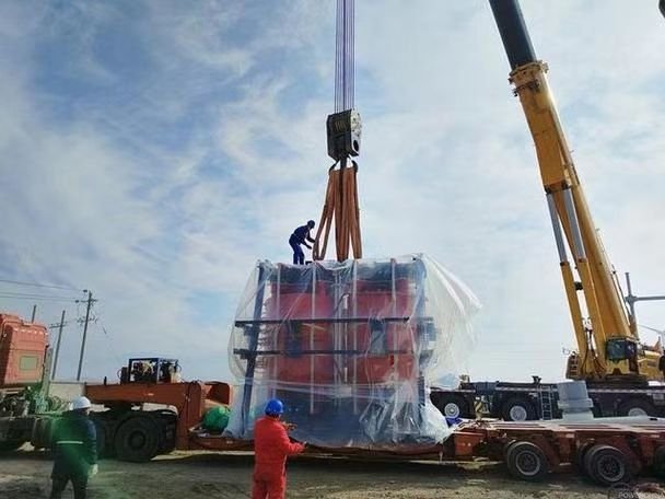
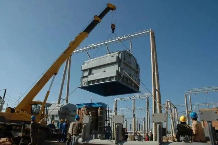
How Are Lifting and Handling Procedures Specified?
Handling and lifting power transformers is a high-risk operation that requires precise execution, technical documentation, and coordination between engineering, logistics, and safety teams. These large, heavy, and delicate machines contain sensitive windings, bushings, and cores that can be damaged by shock, tilt, torsion, or incorrect lifting angles. Without strict adherence to engineered lifting plans and manufacturer specifications, a single lifting error can lead to catastrophic mechanical failure, injury, or loss of warranty. Therefore, all handling procedures are thoroughly defined by technical standards, transformer design documents, and project-specific logistics protocols.
Lifting and handling procedures for power transformers are specified through detailed manufacturer-provided lifting drawings, structural analysis of lifting lugs, center-of-gravity documentation, handling manuals, and site-specific rigging plans. These procedures define the correct lifting points, sling angles, crane capacity, spreader beam configurations, and safety clearances. They are governed by standards such as IEC 60076-22-1, ASME B30.20, and ISO 12480-1. Failure to follow the defined procedures can result in transformer damage, safety violations, and invalidated warranties.
Transformers can be lifted from any structural point on the tank.False
Transformers must only be lifted using certified lifting lugs as defined by engineering drawings. Unauthorized lifting points can cause deformation.
Lifting drawings must indicate center of gravity and sling angles.True
To ensure balanced and stable lifting, the drawing must show the CG location, required sling angles, and rigging details.
A spreader beam is necessary when lifting large transformers.True
A spreader beam maintains vertical sling alignment and prevents compressive stress on bushings or tank edges.
Key Elements of Transformer Lifting and Handling Specification
| Specification Element | Purpose |
|---|---|
| Lifting Drawing | Shows locations of lifting lugs, CG, sling angles, and equipment |
| Rigging Plan | Defines crane type, sling type, spreader beam dimensions |
| Tank Stress Calculations | Ensures no deformation under self-weight and sling tension |
| Transport and Handling Manual | Step-by-step instructions from OEM |
| Crane Load Chart | Confirms crane capacity at reach and height |
| Field Safety Plan | Assigns roles, defines safety zone, and handling sequence |
Manufacturers provide lifting instructions specific to each transformer model and configuration, not generic procedures.
Typical Transformer Lifting Configurations
| Lifting Case | Description | Method Used |
|---|---|---|
| Vertical Lifting | Factory lifting for installation/removal of main tank | 4-point lift using top lifting lugs + spreader beam |
| Horizontal Skid Movement | Lifting for base skid placement or trailer positioning | Forklift pockets or jack pads under base |
| Accessory Handling | Lifting OLTC chambers, conservator tanks, bushings | Small chain hoists or mobile cranes with lifting rings |
| Tilted Lifting (not preferred) | Sometimes used in low-clearance installations | Requires special angle control and spreaders |
Never lift a transformer using bushings, radiators, or unreinforced edge points.
Sample Lifting Drawing Parameters
A typical OEM-supplied lifting drawing includes:
- Transformer outline with marked lifting lug positions
- Center of gravity (CG) clearly shown with coordinates
- Required sling angle (e.g., 60° from horizontal)
- Minimum spreader beam length (to avoid tank compression)
- Sling specifications (length, diameter, material)
- Net and gross weight of transformer with/without oil
- Instructional notes (e.g., “Remove bushings before lifting”)
These drawings are reviewed and signed off during Factory Acceptance Testing (FAT) and logistics planning.
Rigging Equipment and Safety Controls
| Equipment Type | Specification Considerations |
|---|---|
| Sling and Shackles | WLL rating must exceed transformer weight with 5:1 safety factor |
| Spreader Beam | Designed to match sling spacing and reduce side loads |
| Crane/Hoist | Load rating at lift radius and height must exceed gross weight |
| Load Cells | For real-time load monitoring and balance verification |
| Anti-sway Guides | Control wind-induced motion or crane overshoot |
Each component must be certified and traceable, with inspection records available.
Site Handling Safety and Operational Sequence
| Step | Action |
|---|---|
| 1. Pre-lift Meeting | Assign roles, review lifting plan, verify wind and weather conditions |
| 2. Equipment Inspection | Check shackles, slings, crane brakes, spreader beams |
| 3. Area Clearance | Mark safety zone, restrict unauthorized access |
| 4. Trial Lift | Lift 100 mm off ground to confirm balance and clearance |
| 5. Controlled Lift | Raise to required height slowly, using tag lines for control |
| 6. Placement/Lowering | Position on foundation or skid with shims, check level |
| 7. Post-lift Inspection | Visual check for deformation, lug cracks, bushing shift, etc. |
Weather limits (e.g., max wind speed 10 m/s) are strictly enforced during outdoor operations.
International Standards Governing Lifting and Handling
| Standard | Focus Area |
|---|---|
| IEC 60076-22-1 | Transport and installation of power transformers |
| ASME B30.20 | Below-the-hook lifting devices (spreader beams, clamps) |
| ISO 12480-1 | Crane operations — Planning, maintenance, load control |
| OSHA 1926.753 | Safety in hoisting and rigging operations |
| EN 13155 | Non-fixed load lifting attachments |
OEMs often supplement these with project-specific lifting procedures based on transformer rating and site logistics.
Common Handling Mistakes and Their Consequences
| Mistake | Potential Consequence |
|---|---|
| Lifting without spreader beam | Tank deformation, bent bushings, seal leaks |
| Exceeding recommended sling angle | Excess lateral force, damaged lifting lugs |
| Lifting from base instead of lugs | Frame bending, internal core misalignment |
| No trial lift before full hoist | Loss of control, imbalance, sudden swing |
| Ignoring CG offset | Unstable lift, dropped unit, injury or loss |
All these risks are avoidable through strict adherence to OEM guidance and certified rigging practices.
Example: 100 MVA Transformer Factory Lift
- Transformer Specs: 100 MVA, 220/110 kV, 142 tons (without oil)
- Lifting Method: 4-point top-lug lift with 45° sling angle
Rigging Plan:
- Two cranes (200-ton and 120-ton) synchronized
- 5-meter spreader beam with lateral bracing
- Digital load cell between spreader and crane hook
- Safety Controls: Wind speed monitor, anti-sway bars, crew of 6 trained riggers
- Result: Transformer lifted from test bay to transport skid without damage
What Documentation Accompanies the Transformer During Shipping?
Shipping a power transformer involves far more than physically moving the equipment—it’s a compliance-heavy, internationally regulated process that requires a complete set of technical, legal, commercial, and safety documentation. Without these, customs clearance, insurance claims, project acceptance, and warranty validation can all be compromised. Missing or incorrect documents can lead to delays, legal penalties, or even transformer rejection upon arrival. For both domestic and international deliveries, manufacturers must prepare and package a standardized documentation bundle aligned with contractual, logistical, and regulatory requirements.
The documentation that accompanies a transformer during shipping includes the packing list, test certificates, bill of lading, transport drawings, installation manuals, lifting instructions, warranty declarations, export/import documents, and inspection reports. These documents serve legal, technical, and commercial purposes, and are usually compiled into a “shipping dossier” or “technical handover package.” Their format and contents must comply with IEC, ISO, and local customs regulations.
Shipping a transformer requires only the bill of lading and invoice.False
Multiple technical, safety, and regulatory documents must accompany transformer shipments, beyond just commercial paperwork.
Test certificates and packing lists are essential for project acceptance and customs clearance.True
They prove the transformer was manufactured and packed as specified, supporting both technical validation and import compliance.
Transformer manuals and lifting drawings must be included in the shipment.True
Handling and installation documentation ensures safe unloading, placement, and commissioning.
Comprehensive Documentation Package for Transformer Shipping
| Document Type | Purpose |
|---|---|
| Commercial Documents | Enable legal shipping, customs clearance, and invoicing |
| Technical Documents | Support safe transport, inspection, and installation |
| Test Certificates | Verify performance and compliance with standards |
| Regulatory Documents | Satisfy import/export, environmental, and safety rules |
1. Commercial Shipping Documents
| Document | Description |
|---|---|
| Proforma Invoice | Issued pre-shipment, states value and contract conditions |
| Commercial Invoice | Final invoice for customs and buyer payment processing |
| Packing List | Lists all crates, components, gross/net weights, and dimensions |
| Bill of Lading (B/L) | Legal transport contract between shipper and carrier |
| Certificate of Origin | Confirms manufacturing location, required for tariff classifications |
| Insurance Certificate | Indicates coverage during transport, handling, and loading |
| Letter of Credit (if any) | Banking instrument tied to shipping documents for payment release |
Each item must be cross-referenced with actual cargo content and match contract details.
2. Technical and Engineering Documents
| Document | Purpose |
|---|---|
| Transport Drawing | Shows lifting points, center of gravity, sling angles, and mounting |
| Lifting and Handling Guide | Defines correct rigging and movement techniques |
| Installation Manual | Step-by-step procedures for site installation and assembly |
| Assembly Drawings | Detailed diagrams of accessories like radiators, bushings, OLTC |
| GA Drawing (General Arrangement) | Indicates overall dimensions and spatial layout |
| Foundation Plan | Base design and bolt arrangement for civil interface |
| Nameplate Drawing | Copy of nameplate for early ID, inspection, and site records |
These documents allow safe unloading and installation without waiting for engineers to arrive onsite.
3. Quality Assurance and Test Certificates
| Document | Significance |
|---|---|
| Routine Test Report | IEC 60076-1 required factory tests (insulation, ratio, impedance) |
| Type Test Certificates | If performed, includes temperature rise, lightning impulse, etc. |
| Special Test Reports | Customer-specified tests such as noise level, partial discharge |
| Test Certificates for Accessories | Bushing test, OLTC test, CT/PT calibration |
| Inspection Release Note (IRN) | Signed approval of shipment condition by QA and customer inspector |
| Calibration Certificates | Traceability of test equipment used during factory acceptance |
Often bundled into a "Quality Dossier", these validate that the transformer meets contract and standard requirements.
4. Warranty and Declaration Documents
| Document | Function |
|---|---|
| Warranty Certificate | Defines terms (duration, scope, exclusions) of warranty coverage |
| Manufacturer’s Declaration of Conformity | Declares compliance with IEC/ISO or CE standards |
| Declaration of No PCB/Oil Compliance | Confirms dielectric fluid meets environmental rules |
| Spare Parts List | Inventory of recommended spares with part numbers |
In case of disputes or claims, warranty documents serve as the legal basis for remedial action.
5. Regulatory and Compliance Documents
| Document | Legal or Customs Use |
|---|---|
| Export License (if applicable) | For controlled items such as grid-critical transformers |
| Customs Import Forms | Varies by destination country (e.g., HS code declaration) |
| Dangerous Goods Declaration (if oil-filled) | Indicates if unit contains flammable or hazardous substances |
| Environmental Compliance Statement | Confirms REACH/RoHS/oil purity standards where required |
Failure to produce these may result in customs hold, rejection, or fines.
Packaging and Shipment Documentation (Attached to Crates)
| Document | Location | Purpose |
|---|---|---|
| Crate Label/Sticker | Affixed to each crate | Shows crate number, contents, weight, handling symbols |
| Shipping Markings | Stenciled on tank | Shows transformer serial number, CG, lifting points |
| Danger Labels (if any) | On oil drums/crates | Complies with IMO/ADR labels for flammable goods |
| Copy of Packing List | In waterproof pouch | Allows identification during customs or unloading |
Often, two complete physical sets of documents are shipped: one with the cargo and one via air courier to the consignee.
Example: Export Transformer Shipping Documentation Set
Transformer: 250 MVA, 220/66/11 kV
Destination: Europe
Document Package Included:
- Commercial Invoice and Packing List
- Bill of Lading (Original x3)
- Certificate of Origin and EUR.1
- Transport and Lifting Drawings
- Type and Routine Test Reports (IEC 60076)
- Oil Certificate (Moisture, BDV, PCB-Free)
- Installation, Operation, and Maintenance Manual
- Warranty Certificate (5 Years)
- Environmental Compliance Declaration (RoHS, REACH)
- Bushing and OLTC Accessory Manuals
- Customs HS Code Sheet with Tariff Classification
How Are Accessories and Conservator Tanks Shipped?
Shipping a power transformer involves not only the main tank but also a wide range of critical accessories such as conservator tanks, radiators, bushings, OLTC motor drives, cooling fans, control cabinets, and monitoring devices. These components are essential for final assembly, commissioning, and operation at site, and are therefore shipped as part of a coordinated logistics operation. Improper packaging, identification, or handling of these accessories can delay commissioning, result in component damage, or void warranty coverage. To mitigate these risks, the shipping of transformer accessories and conservator tanks follows well-defined procedures, international standards, and tailored packaging protocols.
Accessories and conservator tanks are typically shipped separately from the transformer main tank due to size, fragility, and handling requirements. They are packed in custom wooden crates, shrink-wrapped or sealed against moisture, labeled with component ID and serial numbers, and documented in the packing list. Depending on project logistics, they are shipped either inside containers or alongside the main tank as part of a coordinated load. Standards such as IEC 60076-22-1 and ISO 668 guide accessory transport and protection. Pre-shipment inspections and detailed documentation ensure traceability and assembly readiness at site.
Conservator tanks are usually mounted on transformers before shipping.False
Conservator tanks are typically shipped separately to reduce transport height and protect them from damage.
Bushings and radiators are often packed in crates to prevent breakage.True
Accessories like bushings and radiators are fragile and must be transported in secure, cushioned crates to avoid damage.
All accessories must be listed in the transformer packing list.True
A complete packing list ensures that all parts arrive at site for full transformer assembly and commissioning.
Standard Procedure for Shipping Transformer Accessories
| Component | Shipping Method | Packaging Standard |
|---|---|---|
| Conservator Tank | Wooden crate or frame, separate | Shrink-wrapped or bolted crate |
| Bushings | Foam-lined wooden crates | With flange caps and shock indicators |
| Radiators | Bundled or individual crates | Steel-braced and cushioned |
| OLTC Motor Drive | Sealed box with mounting kit | Labeled and moisture-protected |
| Cooling Fans | Wooden crate or palletized | Wrapped and shock-protected |
| Control Cabinets | Crated or containerized | Marked for “This Side Up” |
| Cable Sets | Coil-packed and tagged | In bags or small crates |
| Pressure Relief Valves & Breathers | Packed with desiccants | Boxed, with part ID tags |
Each crate is marked with part number, transformer serial number, destination site, and orientation instructions.
Why Are Conservator Tanks Shipped Separately?
| Reason | Explanation |
|---|---|
| Height Restrictions | Pre-mounted conservators increase total transport height, risking bridge/tunnel clearance issues |
| Structural Integrity | Vibration during transport can damage mounting brackets or lead to weld cracking |
| Ease of Handling | Separately packed tanks allow staged installation and better lifting options |
| Surface Treatment Protection | Painted tanks are less likely to suffer abrasions when packed individually |
They are often pre-assembled at the factory, fully painted, fitted with desiccant breathers, level indicators, and end covers, and then crated.
Documentation for Accessory Shipments
| Document | Description |
|---|---|
| Accessory Packing List | Lists each crate, content, dimensions, and weight |
| Component Drawings | Installation and assembly drawings for each accessory |
| Spare Parts Identification | For critical accessories like bushings, fans, or relays |
| Test Certificates (if applicable) | For bushings, OLTC drive units, cooling fans |
| Crate Numbering and Labeling Sheet | Cross-references crate number with contents and transformer ID |
Multiple copies of the accessory packing list are shipped: one with the goods, one via air/email, and one attached to the main shipping folder.
Shipping Configuration: Factory Planning Table
| Scenario | Main Tank Shipment | Accessories Shipment | Container Use |
|---|---|---|---|
| Domestic Road Only | On multi-axle trailer | On second trailer or truck | Not required |
| Road + Sea Export | Breakbulk vessel | In container, shrink-wrapped crates | 20ft/40ft HC |
| Modular Dry-Type Delivery | In crate | In same crate or palletized | Combined |
The conservator tank and accessories must arrive at site before or with the main tank to avoid commissioning delays.
Protection Measures During Accessory Shipping
| Risk Factor | Protection Measure |
|---|---|
| Moisture Ingress | Heat-sealed shrink wrap, desiccant bags, VCI film |
| Impact or Shock | Foam lining, steel reinforcement, “Fragile” labels |
| Component Mix-up | Color-coded or QR-coded tagging per drawing set |
| Unauthorized Opening | Tamper-evident seals or steel banding |
| Oil Leaks (for prefilled components) | Drip-proof trays or secondary containment |
In high humidity regions, accessories may be shipped in climate-controlled containers or with data loggers monitoring temperature and RH.
Example: Accessory Shipment Plan for 160 MVA Power Transformer
- Accessories Included: 3 bushings (220 kV), OLTC drive unit, 4 radiators, 1 conservator tank, control cabinet
Packaging:
- Bushings in foam-lined wooden crates with desiccants
- Conservator tank shrink-wrapped, bolted to a steel-reinforced pallet
- Cabinet in upright crate with “Keep Dry” and “Do Not Tilt” markings
- Containerized Shipping: All packed in one 40-foot high cube container with center-of-gravity labels
- Documentation: Itemized packing list, photos of contents, serial-matching sheet
- Customs Note: All crate contents declared by HS code, with Certificate of Origin
Accessories arrived at site 4 days prior to the main tank, allowing civil and electrical teams to begin staging and foundation prep.
Conclusion
Packaging, transportation, and lifting are critical stages in the delivery of a power transformer and must be executed according to precise specifications. Proper protective packaging, secure transport logistics, and careful lifting techniques ensure the transformer arrives at its destination in optimal condition. Adhering to these procedures protects the equipment’s value and performance while ensuring a safe and successful installation process.
FAQ
Q1: How are power transformers typically packaged for transport?
A1: Power transformers are packaged using robust, weather-resistant methods to protect against mechanical damage, moisture, and contamination during shipping. Packaging methods include:
Vacuum-sealed or nitrogen-filled for moisture-sensitive components
Export-grade wooden crates or steel frames for accessories
Oil-filled tanks sealed and pressurized for leak prevention
Shrink-wrapped and corrosion-protected parts
For long-distance or overseas shipping, shock and tilt indicators are added to monitor handling.
Q2: What are the transport requirements for large power transformers?
A2: Transporting large transformers involves heavy-haul logistics and must comply with:
Local road weight and size regulations
Use of multi-axle trailers or modular transporters
Coordination with transport authorities for permits and escorts
Route surveys to assess bridges, turns, and clearances
Overseas shipments are usually done via flat-rack containers, breakbulk shipping, or Ro-Ro vessels for units over 100 MVA.
Q3: What lifting specifications must be followed for power transformers?
A3: Transformers are lifted using:
Certified lifting lugs and shackles integrated into the tank frame
Spreader bars to distribute load evenly
Cranes or gantries rated beyond total weight (with oil, core, and accessories)
Lifting diagrams provided by the manufacturer
Key lifting precautions:
Avoid side loads or jerking motions
Lift only from designated points
Never lift with accessories mounted unless specified
Q4: How are accessories and parts transported?
A4: Accessories like bushings, radiators, conservator tanks, and tap changers are:
Disassembled and packed separately
Labeled and packed in anti-static, shock-proof crates
Provided with a packing list and installation instructions
Small parts are containerized; large accessories may be crated or placed in a separate shipment.
Q5: Who is responsible for transport, and what documentation is included?
A5: Responsibility is defined by Incoterms (EXW, FOB, CIF, DDP, etc.) and may lie with the manufacturer or buyer. Shipment typically includes:
Bill of lading
Packing list
Lifting and handling instructions
Installation and maintenance manuals
Test certificates and factory acceptance test (FAT) reports
Insurance coverage is recommended during all stages of transport and handling.
References
IEEE C57.93: Installation of Liquid-Filled Transformers
https://standards.ieee.org/standard/C57_93-2022.html
Doble Engineering: Heavy Equipment Handling for Substations
https://www.doble.com/solutions/installation-and-logistics/
NREL: Shipping and Storage of Power Transformers
https://www.nrel.gov/docs/fy22osti/transformer-transport-guidelines.pdf
International Maritime Organization (IMO): Cargo Transport Guidelines
https://www.imo.org/en/OurWork/Safety/Pages/DangerousGoods.aspx
ScienceDirect: Transport Safety of Electrical Power Equipment
https://www.sciencedirect.com/science/article/pii/S1364032119311345

