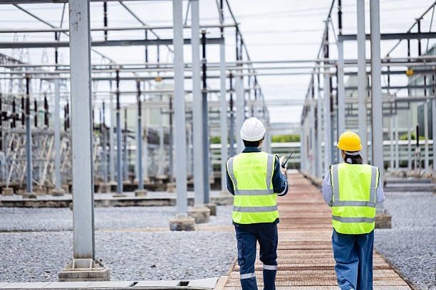
Selecting the correct voltage rating is one of the most important decisions when purchasing a power transformer. An improperly rated transformer can result in inefficient power transmission, equipment damage, increased energy losses, and costly system failures. Because every electrical network has unique voltage requirements, buyers must consider not only the primary and secondary voltages but also insulation levels, system configuration, future expansion, and applicable industry standards. Understanding these voltage ratings ensures reliable operation, regulatory compliance, and long-term system performance.
When selecting a power transformer, the most important voltage ratings to consider include the primary voltage, secondary voltage, highest system voltage, insulation level (BIL), tap changer voltage range, frequency rating, and system grounding configuration. These parameters ensure the transformer is compatible with the electrical network, operates safely under normal and fault conditions, and provides reliable voltage regulation throughout its service life.
Since power transformers are designed to operate for decades, choosing the appropriate voltage ratings from the beginning helps avoid expensive modifications, improves operational efficiency, and supports future growth of the electrical system.
What Voltage Ratings Should Be Considered When Selecting Power Transformers?
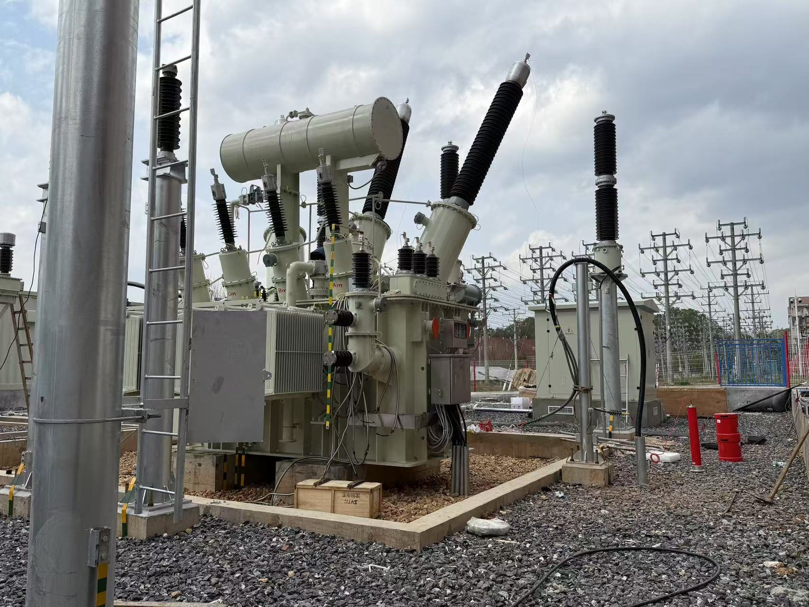
Selecting the correct voltage rating is one of the most critical steps in choosing a power transformer. A transformer with an inappropriate voltage rating can lead to insulation stress, poor voltage regulation, equipment damage, reduced efficiency, and even system failures. Because power systems operate at multiple voltage levels—from generation and transmission to distribution and end-user applications—the transformer must be carefully matched to both the electrical network and the connected load. Understanding primary voltage, secondary voltage, insulation levels, tap changer range, and future system expansion is essential for making the right selection.
When selecting a power transformer, you should consider the primary voltage, secondary voltage, system frequency, insulation level (BIL), voltage regulation requirements, tap changer range, system grounding method, and potential future load expansion. Matching these voltage ratings to your electrical system ensures safe operation, high efficiency, long service life, and compliance with applicable standards.
Choosing a power transformer only requires matching the primary voltage to the utility supply.False
Proper transformer selection requires evaluating both primary and secondary voltages, insulation coordination, voltage regulation, tap changer capability, system frequency, and future operating conditions—not just the incoming supply voltage.
Why are voltage ratings so important?
Power transformers connect electrical systems operating at different voltage levels.
Their primary function is to safely convert one voltage to another while maintaining efficient power transfer.
Incorrect voltage selection may result in:
- Excessive insulation stress
- Overheating
- Poor equipment performance
- Reduced transformer lifespan
- Increased maintenance costs
Proper voltage matching ensures reliable and efficient operation throughout the transformer's service life.
Why voltage ratings matter
| Selection Factor | Impact |
|---|---|
| Correct voltage matching | Safe and reliable operation |
| Proper insulation coordination | Reduced failure risk |
| Suitable voltage regulation | Stable equipment performance |
| Future expansion capability | Longer asset usefulness |
What is the primary voltage rating?
The primary voltage rating is the voltage applied to the transformer's input winding.
It should match the available utility or transmission system voltage.
Typical primary voltages include:
- 11 kV
- 22 kV
- 33 kV
- 66 kV
- 110 kV
- 132 kV
- 220 kV
- 400 kV and above
Selecting the correct primary voltage avoids unnecessary stress on the insulation system and ensures efficient transformer operation.
What is the secondary voltage rating?
The secondary voltage is the output voltage supplied to downstream equipment.
It depends on the application.
Examples include:
| Application | Typical Secondary Voltage |
|---|---|
| Distribution networks | 11 kV, 13.8 kV, 33 kV |
| Industrial plants | 6.6 kV, 11 kV, 13.8 kV |
| Commercial buildings | 400 V, 415 V, 480 V |
| Data centers | 400 V, 480 V |
| Renewable energy substations | Grid-specific voltage levels |
The secondary voltage should match the requirements of connected equipment while maintaining acceptable voltage regulation.
Why should the transformation ratio be considered?
The voltage ratio determines how the transformer converts voltage between the primary and secondary windings.
The correct transformation ratio ensures:
- Proper equipment operating voltage
- Efficient power transfer
- Compliance with system design
- Stable electrical performance
Even a small mismatch can affect sensitive industrial and commercial equipment.
How does system frequency influence voltage selection?
Power transformers are designed for specific operating frequencies, typically:
- 50 Hz
- 60 Hz
Frequency affects:
- Core magnetic flux
- Transformer losses
- Heating characteristics
- Voltage capability
Using a transformer designed for the wrong frequency may lead to excessive core saturation, overheating, and reduced efficiency.
Why is the Basic Insulation Level (BIL) important?
Voltage rating alone does not determine whether a transformer can withstand transient overvoltages.
The Basic Insulation Level (BIL) defines the transformer's ability to withstand:
- Lightning impulses
- Switching surges
- Temporary overvoltages
Higher-voltage installations generally require higher BIL ratings.
Typical considerations
| Installation | Relative BIL Requirement |
|---|---|
| Indoor commercial systems | Moderate |
| Industrial substations | High |
| Utility transmission substations | Very high |
| Renewable energy substations | High |
Proper insulation coordination improves reliability and protects the transformer from surge-related failures.
Why should tap changer range be evaluated?
Power system voltage is rarely constant.
Load changes and network conditions can cause voltage fluctuations.
Tap changers allow the transformer to adjust its voltage ratio to maintain a stable secondary voltage.
Common options include:
- Off-circuit tap changers (OCTC)
- On-load tap changers (OLTC)
An appropriate tap range helps compensate for:
- Utility voltage variations
- Seasonal load changes
- Future network expansion
How does the grounding system affect voltage selection?
Different electrical systems use different grounding methods, including:
- Solid grounding
- Resistance grounding
- Reactance grounding
- Ungrounded systems
Grounding configuration influences:
- Winding connections
- Neutral availability
- Insulation requirements
- Protection system design
Transformer voltage ratings should always be compatible with the intended grounding arrangement.
Why should future expansion be considered?
Many facilities experience increasing electrical demand over time.
When selecting voltage ratings, engineers should evaluate:
- Planned production expansion
- Additional buildings
- Renewable energy integration
- Electric vehicle charging
- Data center growth
Choosing a transformer with appropriate voltage flexibility and tap-changing capability can reduce the need for costly future replacements.
How do voltage requirements differ by industry?
Different industries operate at different voltage levels based on their electrical loads and infrastructure.
Typical industry voltage requirements
| Industry | Typical Voltage Considerations |
|---|---|
| Electric utilities | High-voltage transmission and distribution |
| Manufacturing | Medium-voltage motor systems and process equipment |
| Mining | Long-distance medium-voltage distribution |
| Renewable energy | Generator step-up to transmission voltage |
| Data centers | Medium-voltage supply with low-voltage distribution |
| Commercial buildings | Medium-voltage utility service with low-voltage building distribution |
| Transportation | Traction power and substation voltage conversion |
Selecting voltage ratings appropriate to the industry improves safety, efficiency, and operational reliability.
What international standards should be followed?
Voltage ratings should comply with recognized industry standards to ensure compatibility and safety.
Common standards include those published by the:
- International Electrotechnical Commission
- Institute of Electrical and Electronics Engineers
These standards define requirements for:
- Rated voltages
- Insulation coordination
- Testing procedures
- Temperature rise
- Dielectric performance
Compliance helps ensure that transformers operate reliably within the intended electrical system.
Why Are Primary and Secondary Voltage Ratings Critical for Power Transformers?
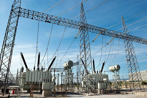
Power transformers are designed to transfer electrical energy efficiently between circuits operating at different voltage levels. Their ability to perform this function safely and reliably depends largely on selecting the correct primary and secondary voltage ratings. If either voltage rating is incorrectly specified, the transformer may experience excessive insulation stress, poor voltage regulation, overheating, reduced efficiency, equipment malfunction, or even catastrophic failure. Whether the transformer is installed in a utility substation, industrial facility, renewable energy plant, data center, or commercial building, accurately matching the input and output voltages to the electrical system is fundamental to ensuring reliable power delivery and long service life.
Primary and secondary voltage ratings are critical because they determine how a power transformer interfaces with the electrical network and connected equipment. The primary voltage must match the incoming supply, while the secondary voltage must provide the correct operating voltage for downstream loads. Proper voltage selection improves efficiency, maintains voltage stability, protects equipment, and ensures compliance with electrical system requirements and international standards.
As long as a transformer has the correct power rating (kVA or MVA), small differences in primary or secondary voltage ratings are not important.False
Voltage ratings are just as important as power ratings. Incorrect primary or secondary voltages can cause equipment damage, poor voltage regulation, insulation stress, and unsafe operating conditions, even if the transformer's power capacity is adequate.
What are primary and secondary voltage ratings?
Every power transformer has two fundamental voltage ratings:
- Primary voltage — the voltage applied to the input winding from the electrical supply.
- Secondary voltage — the voltage delivered by the output winding to the connected electrical load.
The transformer converts electrical energy between these voltage levels while maintaining essentially the same power (minus normal losses).
Correctly specifying both voltages ensures the transformer integrates seamlessly into the electrical system.
Basic transformer voltage relationship
| Voltage Rating | Function |
|---|---|
| Primary voltage | Matches the incoming utility or transmission supply |
| Secondary voltage | Supplies the required operating voltage for equipment |
| Voltage ratio | Determines the transformation between input and output |
Why must the primary voltage match the power supply?
The primary winding is designed to operate at a specific system voltage.
If the applied voltage differs significantly from its rated value:
- Magnetic flux may become too high or too low.
- Core losses may increase.
- Insulation stress can rise.
- Transformer temperature may exceed design limits.
- Equipment lifespan may be reduced.
Operating at the correct primary voltage allows the transformer to achieve its intended efficiency and thermal performance.
Typical primary voltages include:
- 11 kV
- 22 kV
- 33 kV
- 66 kV
- 110 kV
- 132 kV
- 220 kV
- 400 kV and above
Why is the secondary voltage equally important?
The secondary voltage must match the requirements of the connected electrical equipment.
Different applications require different output voltages.
For example:
| Application | Typical Secondary Voltage |
|---|---|
| Industrial motors | 6.6 kV, 11 kV, 13.8 kV |
| Commercial buildings | 400 V, 415 V, 480 V |
| Data centers | 400 V, 480 V |
| Distribution networks | 11 kV, 13.8 kV, 33 kV |
| Renewable energy substations | Utility-specific grid voltage |
Incorrect secondary voltage may result in:
- Motor overheating
- Reduced equipment performance
- Control system malfunctions
- Excessive current draw
- Premature equipment failure
Matching the secondary voltage to the load is therefore essential for safe and efficient operation.
How do voltage ratings determine the transformation ratio?
The relationship between primary and secondary voltages defines the transformer's voltage ratio.
Where:
- (V_p) = Primary voltage
- (V_s) = Secondary voltage
- (N_p) = Primary winding turns
- (N_s) = Secondary winding turns
The correct ratio ensures that electrical equipment receives the voltage it was designed to operate at while maintaining efficient power transfer.
How do incorrect voltage ratings affect transformer performance?
Even when the transformer has sufficient power capacity, incorrect voltage ratings can significantly reduce system performance.
Potential consequences include:
- Increased core losses
- Excessive winding current
- Poor voltage regulation
- Reduced efficiency
- Insulation degradation
- Higher operating temperatures
- Increased maintenance requirements
Selecting the correct voltage ratings minimizes these risks and helps achieve the expected service life.
Effects of incorrect voltage selection
| Issue | Possible Consequence |
|---|---|
| Incorrect primary voltage | Core saturation or under-excitation |
| Incorrect secondary voltage | Improper equipment operation |
| Voltage mismatch | Reduced efficiency and reliability |
| Excessive voltage stress | Insulation aging and failure |
Why is voltage regulation important?
Electrical loads change continuously during operation.
Large motors starting, production equipment cycling, or fluctuating renewable generation can all affect system voltage.
Power transformers help maintain stable output voltage through proper design and, where required, tap-changing mechanisms.
Common solutions include:
- Off-circuit tap changers (OCTCs)
- On-load tap changers (OLTCs)
These devices allow the transformer to compensate for supply voltage variations while maintaining the desired secondary voltage.
Stable voltage improves:
- Motor performance
- Equipment lifespan
- Production quality
- Power system reliability
How do voltage ratings influence insulation design?
Higher voltage ratings require stronger insulation systems.
Transformer insulation must withstand:
- Continuous operating voltage
- Temporary overvoltages
- Lightning impulses
- Switching surges
The required insulation level increases with system voltage, influencing winding design, clearances, and dielectric materials.
Proper insulation coordination helps prevent electrical breakdown and ensures reliable long-term operation.
Why should future expansion be considered?
Electrical systems often grow over time as facilities expand or operating requirements change.
When selecting voltage ratings, engineers should consider:
- Planned production increases
- Additional buildings
- New process equipment
- Renewable energy integration
- Electric vehicle charging infrastructure
Providing appropriate voltage flexibility through transformer design and tap-changing capability can simplify future upgrades and reduce long-term investment costs.
How do voltage requirements vary across industries?
Different industries operate at different voltage levels depending on their equipment and infrastructure.
Typical voltage applications by industry
| Industry | Common Voltage Requirements |
|---|---|
| Electric utilities | High-voltage transmission and distribution |
| Manufacturing | Medium-voltage process equipment |
| Mining | Long-distance medium-voltage distribution |
| Renewable energy | Generator step-up transformers |
| Data centers | Medium-voltage supply with low-voltage distribution |
| Commercial buildings | Medium-voltage service with low-voltage utilization |
| Transportation | Traction substations and station distribution |
Selecting the appropriate voltage ratings for each application improves safety, efficiency, and operational reliability.
Why should voltage ratings comply with international standards?
Voltage ratings should align with recognized engineering standards to ensure compatibility and safe operation.
The most widely used standards are published by the:
- International Electrotechnical Commission
- Institute of Electrical and Electronics Engineers
These standards specify requirements for:
- Rated voltages
- Insulation coordination
- Dielectric testing
- Temperature rise
- Performance verification
Compliance helps ensure transformers perform reliably throughout their expected service life.
How Do System Voltage, Insulation Level, and BIL Affect Transformer Selection?
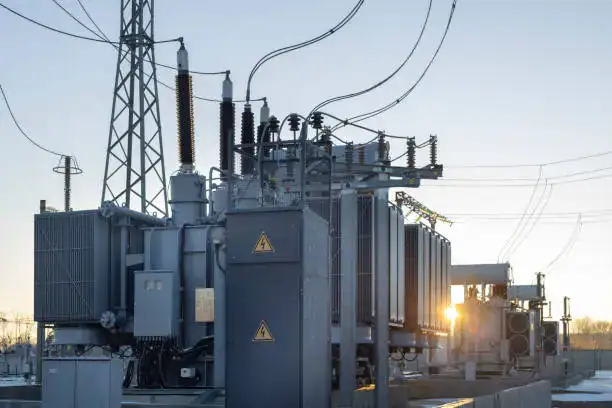
Selecting a power transformer involves much more than matching its power rating and voltage ratio. Engineers must also ensure that the transformer can safely withstand the electrical stresses it will encounter throughout its service life. In addition to the system's operating voltage, factors such as insulation level and Basic Insulation Level (BIL) determine whether the transformer can resist lightning strikes, switching surges, temporary overvoltages, and other transient events. An incorrect insulation specification may not cause immediate problems during normal operation, but it can significantly increase the risk of insulation failure, unplanned outages, and costly equipment damage. Understanding how these three parameters work together is essential for selecting a reliable and durable transformer.
System voltage determines the transformer's normal operating voltage, while the insulation level and Basic Insulation Level (BIL) define its ability to withstand temporary and transient overvoltages. Selecting the correct combination ensures safe operation, reliable insulation performance, compliance with industry standards, and long service life in utility, industrial, commercial, and renewable energy applications.
A transformer with the correct voltage rating automatically has adequate insulation for every installation.False
Voltage rating defines normal operating conditions, while insulation level and Basic Insulation Level (BIL) determine the transformer's ability to withstand lightning impulses, switching surges, and other transient overvoltages. Both must be specified correctly for reliable operation.
Why are system voltage, insulation level, and BIL all important?
Power transformers are exposed to two different types of electrical stress:
- Continuous operating voltage
- Short-duration overvoltages caused by lightning or switching operations
The operating voltage determines how the transformer functions during normal service, while insulation level and BIL ensure it can survive abnormal electrical events without insulation breakdown.
Selecting all three parameters correctly minimizes failure risk and extends transformer life.
What is system voltage?
System voltage is the nominal voltage of the electrical network where the transformer operates.
Examples include:
- 11 kV
- 22 kV
- 33 kV
- 66 kV
- 110 kV
- 132 kV
- 220 kV
- 400 kV and above
The transformer's primary winding must match the incoming system voltage, while the secondary winding supplies the required voltage for downstream equipment.
Incorrect system voltage selection can lead to:
- Excessive magnetic flux
- Increased heating
- Poor efficiency
- Reduced insulation life
- Equipment malfunction
Typical system voltage applications
| Voltage Level | Typical Application |
|---|---|
| 11–33 kV | Distribution networks and industrial facilities |
| 66–132 kV | Regional transmission systems |
| 220–400 kV | High-voltage transmission networks |
| Above 400 kV | Extra-high-voltage transmission systems |
What is insulation level?
The insulation level defines the dielectric strength of the transformer insulation system under normal operating conditions and specified test voltages.
It determines the transformer's ability to withstand:
- Rated power-frequency voltage
- Temporary overvoltages
- Internal electrical stresses
- Aging throughout its service life
The insulation system includes:
- Paper insulation
- Pressboard barriers
- Transformer oil or alternative insulating liquids
- Solid insulation spacers
- Bushings and clearances
Higher system voltages require stronger insulation systems with greater electrical clearances and more robust dielectric materials.
Factors influencing insulation level
| Factor | Influence on Insulation Design |
|---|---|
| System voltage | Determines minimum insulation requirements |
| Installation altitude | May require increased clearances |
| Pollution level | Influences external insulation design |
| Environmental conditions | Affect insulation aging |
| Operating temperature | Impacts insulation lifespan |
What is Basic Insulation Level (BIL)?
Basic Insulation Level (BIL) is a standardized measure of a transformer's ability to withstand high-voltage impulse surges without insulation failure.
These impulse surges are typically caused by:
- Lightning strikes
- Switching operations
- Fault clearing
- Grid disturbances
Unlike the continuous operating voltage, BIL represents a short-duration impulse withstand capability rather than a normal operating condition.
A higher BIL provides greater protection against transient overvoltages and improves system reliability.
Why is BIL different from the rated voltage?
Many engineers mistakenly assume that a transformer operating at a certain voltage automatically has sufficient surge protection.
In reality:
- Rated voltage defines continuous operation.
- BIL defines impulse withstand capability.
For example, two transformers with identical rated voltages may have different BIL ratings depending on their intended installation environment.
A transformer installed in a lightning-prone outdoor substation often requires a higher BIL than one installed inside a protected industrial facility.
Rated voltage vs. BIL
| Parameter | Purpose |
|---|---|
| Rated voltage | Continuous operating voltage |
| Insulation level | Continuous dielectric capability |
| BIL | Lightning and switching impulse withstand capability |
How does installation environment affect insulation requirements?
The installation environment significantly influences insulation selection.
Outdoor substations may experience:
- Direct lightning exposure
- Switching surges
- Pollution
- High humidity
Industrial facilities may experience:
- Harmonics
- Frequent switching
- High temperatures
- Chemical contamination
Coastal installations may require additional insulation coordination because salt contamination increases the likelihood of surface flashover.
Selecting an insulation system appropriate for the operating environment improves long-term reliability.
Why is insulation coordination important?
Insulation coordination ensures that all equipment in a power system has compatible insulation characteristics.
This includes:
- Transformers
- Circuit breakers
- Surge arresters
- Bushings
- Switchgear
- Transmission lines
Proper coordination allows surge arresters to limit overvoltages before they exceed the transformer's BIL, protecting the insulation system from damage.
Without effective insulation coordination, even a transformer with an adequate voltage rating may be vulnerable to transient failures.
Components involved in insulation coordination
| Equipment | Protective Function |
|---|---|
| Transformer | Voltage transformation |
| Surge arrester | Limits transient overvoltages |
| Circuit breaker | Clears fault conditions |
| Bushings | Provide insulated conductor passage |
| Switchgear | Controls and isolates circuits |
How do industry applications influence BIL selection?
Different industries experience different electrical environments.
Typical considerations include:
| Industry | Typical Insulation Considerations |
|---|---|
| Electric utilities | High BIL for outdoor substations and transmission systems |
| Manufacturing | Strong insulation for motor switching and industrial surges |
| Renewable energy | High BIL for exposed solar and wind installations |
| Mining | Robust insulation for harsh operating environments |
| Data centers | Stable insulation performance for high reliability |
| Commercial buildings | Moderate BIL for protected indoor substations |
| Transportation | Enhanced insulation for traction substations and switching operations |
Selecting an appropriate BIL improves operational reliability while avoiding unnecessary equipment costs.
Why should future system expansion be considered?
Electrical systems often evolve over decades.
Future changes may include:
- Higher operating voltages
- Grid expansion
- Renewable energy integration
- Additional substations
- Increased switching activity
Considering future electrical stresses during transformer selection helps avoid premature equipment replacement and supports long-term infrastructure planning.
How do international standards define insulation requirements?
Transformer insulation requirements are established by internationally recognized standards to ensure consistent performance and safety.
The most widely used standards are published by the:
- International Electrotechnical Commission
- Institute of Electrical and Electronics Engineers
These standards specify:
- Rated voltages
- Insulation levels
- BIL values
- Dielectric test procedures
- Impulse withstand tests
- Clearance requirements
Compliance helps ensure transformers can safely withstand both normal operating conditions and expected transient overvoltages.
What Role Do Tap Changers Play in Maintaining Correct Voltage Levels?
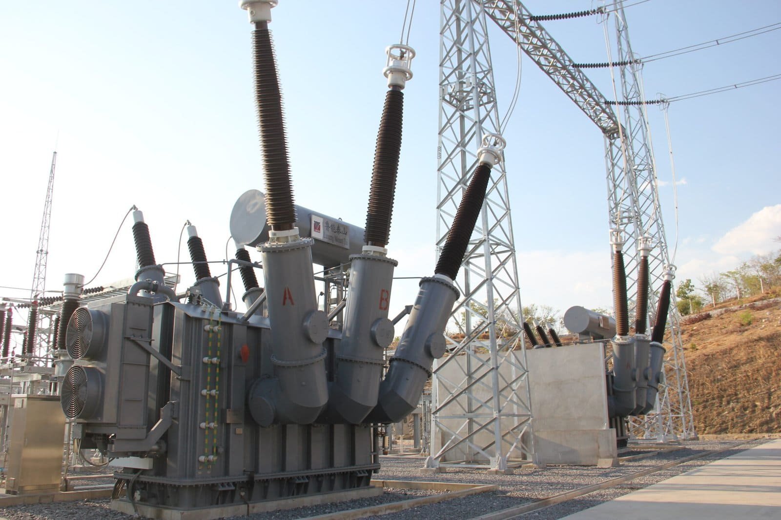
Maintaining a stable voltage is essential for the reliable operation of power systems. However, voltage levels naturally fluctuate due to changing electrical loads, transmission distances, power generation variations, and network operating conditions. Without compensation, these fluctuations can lead to inefficient equipment operation, increased energy losses, overheating, and reduced service life for both transformers and connected electrical equipment. Tap changers address this challenge by adjusting the transformer's voltage ratio, allowing it to maintain the desired output voltage despite variations in the incoming supply or system load. As a result, they are a critical component in modern utility, industrial, renewable energy, and commercial power systems.
Tap changers maintain correct voltage levels by adjusting the effective turns ratio of a power transformer. They compensate for changes in supply voltage and load conditions, helping keep the secondary voltage within acceptable limits. Off-circuit tap changers are adjusted when the transformer is de-energized, while on-load tap changers automatically regulate voltage during normal operation without interrupting the power supply.
Power transformers automatically maintain a constant output voltage without any tap-changing mechanism.False
Transformer output voltage varies with changes in input voltage and load conditions. Tap changers adjust the winding turns ratio to compensate for these variations and maintain the required voltage level.
Why does transformer voltage change?
A transformer's output voltage is influenced by several operating conditions, including:
- Variations in utility supply voltage
- Load fluctuations
- Transmission line voltage drops
- Reactive power demand
- Changes in generation output
Without voltage regulation, these factors may cause the secondary voltage to drift outside the acceptable operating range, affecting connected equipment and overall power quality.
Tap changers compensate for these variations by modifying the transformer's effective voltage ratio.
Common causes of voltage variation
| Cause | Effect on Voltage |
|---|---|
| Heavy electrical loads | Voltage reduction |
| Light loading | Voltage increase |
| Long transmission distances | Line voltage drop |
| Renewable generation variability | Voltage fluctuation |
| Network switching | Temporary voltage changes |
What is a tap changer?
A tap changer is a mechanism that changes the number of active turns in a transformer's winding.
Changing the number of turns alters the voltage ratio between the primary and secondary windings.
Where:
- (V_p) = Primary voltage
- (V_s) = Secondary voltage
- (N_p) = Primary winding turns
- (N_s) = Secondary winding turns
By increasing or decreasing the effective winding turns, the transformer can raise or lower its output voltage to maintain the desired level.
What are the main types of tap changers?
Power transformers generally use one of two tap-changing methods.
Off-circuit tap changers (OCTC)
Off-circuit tap changers can only be operated after the transformer has been completely de-energized.
They are commonly used in applications where voltage adjustments are infrequent.
Typical applications include:
- Industrial plants
- Commercial buildings
- Renewable energy installations with stable operating conditions
Advantages include:
- Simple construction
- Lower cost
- Minimal maintenance
- High reliability
On-load tap changers (OLTC)
On-load tap changers adjust the voltage while the transformer remains energized and supplying electricity.
They are widely used in:
- Utility substations
- Transmission networks
- Distribution systems
- Large industrial facilities
OLTCs automatically respond to voltage changes without interrupting power delivery.
Advantages include:
- Continuous voltage regulation
- Improved power quality
- Stable customer voltage
- Better grid reliability
Comparison of tap changer types
| Feature | Off-Circuit Tap Changer | On-Load Tap Changer |
|---|---|---|
| Operates while energized | No | Yes |
| Automatic regulation | No | Yes |
| Typical applications | Industrial and commercial facilities | Utility and transmission systems |
| Complexity | Lower | Higher |
| Maintenance requirements | Lower | Moderate |
How do tap changers maintain voltage stability?
As electrical demand changes throughout the day, transformer loading also changes.
For example:
- Peak demand increases current and causes voltage drops.
- Reduced demand may cause voltage to rise.
An on-load tap changer continuously monitors the secondary voltage.
When the voltage moves outside a predefined range, the tap changer automatically changes to a higher or lower tap position to restore the desired voltage.
This process helps maintain stable electrical service for connected customers and equipment.
Why is voltage regulation important?
Proper voltage regulation benefits both utilities and end users.
Stable voltage helps:
- Protect electrical equipment
- Improve motor performance
- Reduce overheating
- Improve lighting quality
- Enhance process consistency
- Lower system losses
Poor voltage regulation may result in:
- Motor damage
- Reduced equipment efficiency
- Increased maintenance costs
- Unexpected production interruptions
How do tap changers improve grid reliability?
Modern electrical grids experience continuous changes in:
- Customer demand
- Renewable energy output
- Power generation dispatch
- Network switching
Tap changers allow utilities to:
- Maintain system voltage
- Balance power flow
- Reduce customer voltage complaints
- Improve overall network stability
They also reduce the need for manual voltage adjustments, enabling more efficient grid operation.
Benefits for power systems
| Benefit | Operational Impact |
|---|---|
| Stable voltage | Improved equipment performance |
| Automatic regulation | Reduced operator intervention |
| Better power quality | Increased customer satisfaction |
| Improved grid stability | Higher network reliability |
Why are tap changers especially important for renewable energy?
Renewable energy sources such as solar and wind produce variable electrical output.
Changes in:
- Solar irradiance
- Wind speed
- Battery charging and discharging
can all affect system voltage.
Tap changers help compensate for these fluctuations by automatically adjusting transformer voltage ratios, making renewable energy integration more reliable and supporting compliance with utility grid codes.
How do tap changers support industrial operations?
Manufacturing facilities often operate equipment with rapidly changing electrical demands, including:
- Large motors
- Arc furnaces
- Compressors
- Rolling mills
- Pumps
These loads can create significant voltage variations.
Tap changers help maintain stable voltage, improving:
- Production quality
- Equipment efficiency
- Motor performance
- Overall plant reliability
What factors should be considered when selecting a tap changer?
The appropriate tap-changing system depends on the application and operating conditions.
Key selection factors include:
- Frequency of voltage changes
- Required regulation accuracy
- Load variability
- Maintenance capabilities
- System reliability requirements
- Initial investment budget
Typical application recommendations
| Application | Recommended Tap Changer |
|---|---|
| Utility transmission | On-load tap changer |
| Distribution substation | On-load tap changer |
| Industrial facility | Off-circuit or on-load, depending on load variation |
| Renewable energy plant | On-load tap changer |
| Commercial building | Off-circuit tap changer |
How do international standards address tap changers?
Tap changers are designed and tested according to internationally recognized standards to ensure safe operation and reliable performance.
Key standards are published by the:
- International Electrotechnical Commission
- Institute of Electrical and Electronics Engineers
These standards establish requirements for:
- Voltage regulation performance
- Mechanical endurance
- Electrical endurance
- Temperature rise
- Testing procedures
- Operational reliability
Compliance helps ensure that tap changers perform consistently throughout the transformer's service life.
How Do Frequency and Grounding Configuration Influence Power Transformer Performance?
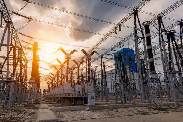
Selecting a power transformer requires careful consideration of many electrical parameters beyond voltage and capacity. Among these, operating frequency and grounding configuration have a significant impact on transformer design, efficiency, insulation performance, protection requirements, and long-term reliability. A transformer designed for the wrong frequency may experience excessive losses, overheating, or magnetic saturation, while an unsuitable grounding configuration can create safety risks, abnormal fault currents, and protection system failures. Understanding how frequency and grounding affect transformer performance helps engineers choose equipment that operates safely and efficiently in utility networks, industrial facilities, renewable energy projects, and commercial infrastructure.
Frequency and grounding configuration influence power transformer performance by affecting magnetic flux, core losses, insulation requirements, fault behavior, protection coordination, and system stability. The correct operating frequency ensures efficient electromagnetic operation, while the appropriate grounding configuration controls fault currents, improves safety, and allows protection systems to function correctly.
Transformer performance is unaffected by operating frequency as long as the voltage rating is correct.False
Operating frequency directly affects magnetic flux density, core losses, heating, and transformer efficiency. A transformer designed for one frequency may not operate safely or efficiently at another frequency.
Why is operating frequency important for power transformers?
A power transformer operates through electromagnetic induction, where alternating current creates a changing magnetic field in the transformer core.
The operating frequency determines how quickly this magnetic field changes.
Common power system frequencies are:
- 50 Hz
- 60 Hz
These frequencies are standard in different regions around the world.
The transformer core, winding design, insulation system, and cooling system must all be optimized for the intended frequency.
Frequency effects on transformer design
| Parameter | Effect of Frequency Change |
|---|---|
| Core flux density | Changes with frequency variation |
| Core losses | Increase if frequency is unsuitable |
| Transformer size | Lower frequency may require larger cores |
| Heating | Can increase under improper operation |
| Efficiency | Depends on optimized frequency design |
How does frequency affect magnetic flux in transformers?
Transformer cores operate within a specific magnetic flux range.
When frequency decreases while voltage remains constant, the magnetic flux density increases.
This may cause:
- Core saturation
- Higher magnetizing current
- Increased losses
- Excessive heating
For example, a transformer designed for 60 Hz operation may experience higher magnetic stress if operated at 50 Hz without proper design adjustments.
Conversely, operating a 50 Hz transformer at 60 Hz is generally less problematic because the magnetic flux decreases, but other design factors still need consideration.
How does frequency influence transformer efficiency?
Transformer efficiency depends on minimizing different types of losses.
Major losses include:
- Core losses (iron losses)
- Copper losses
- Stray losses
Frequency affects core losses because higher frequencies increase:
- Eddy current losses
- Hysteresis losses
Transformer manufacturers optimize:
- Core material
- Lamination thickness
- Magnetic flux density
- Winding arrangement
for the specified frequency.
Frequency impact on performance
| Frequency Condition | Possible Result |
|---|---|
| Correct rated frequency | Maximum efficiency |
| Lower-than-designed frequency | Increased saturation risk |
| Higher-than-designed frequency | Increased core losses |
| Incorrect frequency operation | Reduced reliability |
Why must transformers be designed specifically for 50 Hz or 60 Hz systems?
Although transformers operate on the same electromagnetic principles worldwide, regional power systems use different frequencies.
For example:
- Many countries use 50 Hz networks.
- Other regions use 60 Hz networks.
A transformer designed for a specific frequency considers:
- Core dimensions
- Number of winding turns
- Insulation coordination
- Thermal design
- Loss calculations
Using the correct frequency specification ensures the transformer achieves its expected:
- Efficiency
- Temperature rise limits
- Service life
- Reliability
What is grounding configuration in a power transformer?
Grounding configuration refers to how the transformer windings and neutral points are connected to earth.
The grounding method determines:
- Fault current magnitude
- System voltage behavior during faults
- Protection system operation
- Safety performance
Common transformer grounding configurations include:
- Solid grounding
- Resistance grounding
- Reactance grounding
- Ungrounded systems
- Delta and wye (star) winding arrangements
How does grounding affect transformer protection?
Grounding configuration directly influences how electrical faults behave.
During a ground fault, the grounding method determines the amount of current flowing through the fault path.
Protection systems use this information to:
- Detect faults
- Trip circuit breakers
- Isolate damaged equipment
An incorrect grounding design may cause:
- Insufficient fault current for protection operation
- Excessive fault currents
- Equipment damage
- Safety hazards
Grounding methods comparison
| Grounding Method | Characteristics | Typical Applications |
|---|---|---|
| Solid grounding | High fault current, fast protection response | Utility systems |
| Resistance grounding | Limits fault current | Industrial facilities |
| Reactance grounding | Controls fault magnitude | Medium/high voltage networks |
| Ungrounded | Minimal ground current | Specialized systems |
Why are transformer winding connections important?
Transformer winding connections determine how the transformer interacts with the electrical system.
Common configurations include:
- Delta-delta
- Delta-star
- Star-star
- Star-delta
Each configuration affects:
- Neutral availability
- Harmonic behavior
- Fault current paths
- Phase relationships
For example, a star-connected secondary winding can provide a neutral point for grounding and low-voltage distribution systems.
How does grounding influence insulation requirements?
Grounding affects the voltage stresses experienced by transformer insulation.
A grounded system generally provides better control of:
- Phase-to-ground voltage
- Transient overvoltages
- Fault conditions
An ungrounded system may experience higher temporary overvoltages during ground faults.
Therefore, transformer insulation design must consider:
- System grounding method
- Surge protection
- Basic Insulation Level (BIL)
- Environmental conditions
How do grounding systems improve safety?
Proper grounding provides a controlled path for fault currents.
This helps:
- Protect personnel
- Reduce equipment damage
- Improve fault clearing speed
- Stabilize system voltage
In industrial facilities, grounding design is especially important because large electrical equipment, motors, and process systems can create significant fault energy.
How do frequency and grounding affect renewable energy transformers?
Renewable energy projects introduce additional challenges due to variable generation and complex grid connections.
Solar and wind transformer designs must consider:
- Grid frequency compatibility
- Inverter output characteristics
- Harmonic distortion
- Ground fault behavior
- Grid protection requirements
Proper grounding helps renewable facilities maintain safe operation and comply with grid connection standards.
How do frequency and grounding affect industrial transformers?
Industrial facilities often operate large motors, furnaces, compressors, and production equipment.
Transformers must handle:
- Frequent load changes
- Motor starting currents
- Electrical disturbances
- Harmonic currents
Grounding configuration helps protect equipment from faults, while correct frequency design ensures efficient electromagnetic operation.
Industrial considerations
| Requirement | Performance Impact |
|---|---|
| Correct frequency | Efficient operation and reduced heating |
| Proper grounding | Reliable fault protection |
| Suitable winding connection | Stable voltage performance |
| Correct insulation design | Longer service life |
What standards define frequency and grounding requirements?
Power transformer design follows internationally recognized standards that define electrical performance, testing, and safety requirements.
Important standards are published by:
- International Electrotechnical Commission
- Institute of Electrical and Electronics Engineers
These standards address:
- Rated frequency
- Transformer insulation
- Grounding practices
- Dielectric testing
- Fault withstand capability
- Protection coordination
Compliance ensures transformers operate safely within their intended electrical systems.
How Can You Choose the Right Voltage Rating for Your Power Transformer Application?
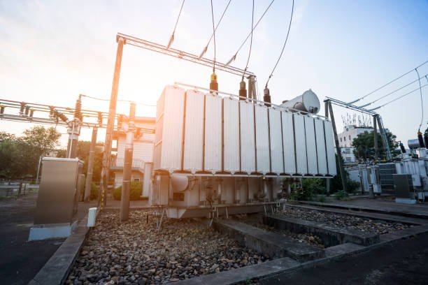
Selecting the correct voltage rating is one of the most important decisions when specifying a power transformer. An incorrectly rated transformer can lead to voltage instability, excessive insulation stress, overheating, reduced efficiency, equipment damage, and unnecessary operating costs. Since every electrical system has unique voltage levels, load characteristics, grounding methods, and future expansion plans, choosing the right voltage rating requires a comprehensive evaluation of both current and long-term operating requirements. By carefully matching the transformer's electrical characteristics to the application, users can improve reliability, maximize efficiency, and extend equipment service life.
To choose the right voltage rating for a power transformer, evaluate the incoming system voltage, required output voltage, system frequency, insulation level, Basic Insulation Level (BIL), grounding configuration, voltage regulation requirements, and future load expansion. Selecting a transformer that matches these parameters ensures safe operation, high efficiency, reliable voltage regulation, and long-term performance.
Selecting the highest available voltage rating always provides the best transformer performance.False
A transformer should be matched to the actual electrical system. Overspecifying voltage ratings can increase costs unnecessarily, while underspecifying them can compromise safety, efficiency, and reliability.
Why is voltage rating selection so important?
A power transformer must operate safely under both normal and abnormal electrical conditions.
Its voltage ratings determine:
- Compatibility with the utility supply
- Proper operation of connected equipment
- Insulation requirements
- Voltage regulation capability
- Long-term reliability
Selecting the appropriate voltage ratings reduces electrical stress and improves overall system performance.
Step 1: Identify the primary (input) voltage
The primary voltage must match the voltage supplied by the utility or upstream electrical network.
Typical primary voltages include:
- 11 kV
- 22 kV
- 33 kV
- 66 kV
- 110 kV
- 132 kV
- 220 kV
- 400 kV and above
Using the correct primary voltage ensures the transformer operates within its designed magnetic flux and insulation limits.
Typical primary voltage applications
| Voltage Level | Typical Application |
|---|---|
| 11–33 kV | Distribution systems and industrial facilities |
| 66–132 kV | Regional transmission |
| 220–400 kV | High-voltage transmission |
| Above 400 kV | Extra-high-voltage transmission |
Step 2: Determine the required secondary (output) voltage
The secondary voltage should match the operating requirements of downstream equipment.
Examples include:
| Application | Typical Secondary Voltage |
|---|---|
| Commercial buildings | 400 V, 415 V, 480 V |
| Manufacturing | 6.6 kV, 11 kV, 13.8 kV |
| Data centers | 400 V, 480 V |
| Distribution substations | 11 kV, 13.8 kV, 33 kV |
| Renewable energy | Utility-specific interconnection voltage |
An incorrect secondary voltage can reduce equipment performance and increase maintenance requirements.
Step 3: Verify the voltage transformation ratio
The ratio between the primary and secondary voltages determines the transformer's turns ratio.
Choosing the correct transformation ratio ensures:
- Proper equipment voltage
- Efficient power transfer
- Stable system operation
- Compliance with electrical design requirements
Step 4: Confirm the operating frequency
Power transformers are designed for specific system frequencies, most commonly:
- 50 Hz
- 60 Hz
Using the wrong frequency can result in:
- Increased core losses
- Magnetic saturation
- Excessive heating
- Reduced efficiency
The transformer's rated frequency should always match the power system where it will operate.
Step 5: Evaluate insulation level and Basic Insulation Level (BIL)
Voltage rating alone is not sufficient.
The transformer must also withstand:
- Lightning impulses
- Switching surges
- Temporary overvoltages
The required insulation level and Basic Insulation Level (BIL) depend on:
- System voltage
- Installation environment
- Surge exposure
- Utility requirements
Outdoor transmission substations generally require higher BIL ratings than indoor commercial installations.
Electrical insulation considerations
| Factor | Design Impact |
|---|---|
| System voltage | Determines insulation requirements |
| BIL | Protects against impulse surges |
| Installation location | Influences surge exposure |
| Environmental conditions | Affects insulation aging |
Step 6: Consider voltage regulation requirements
Power systems rarely operate at a perfectly constant voltage.
Voltage variations occur because of:
- Load changes
- Transmission line impedance
- Renewable generation variability
- Utility network conditions
If precise voltage control is required, consider transformers equipped with:
- Off-circuit tap changers (OCTCs)
- On-load tap changers (OLTCs)
These devices help maintain the desired secondary voltage under changing operating conditions.
Step 7: Review the grounding configuration
The grounding system affects:
- Fault current levels
- Protection coordination
- Insulation design
- Neutral availability
Common configurations include:
- Solid grounding
- Resistance grounding
- Reactance grounding
- Ungrounded systems
The transformer's winding arrangement and voltage ratings should be compatible with the system grounding method.
Step 8: Plan for future expansion
Many electrical systems grow over time.
When selecting voltage ratings, consider future requirements such as:
- Facility expansion
- Additional production equipment
- Renewable energy integration
- Electric vehicle charging
- Increased electrical demand
Allowing for reasonable future growth can reduce the need for costly transformer replacements.
How do voltage requirements differ by industry?
Different industries operate at different voltage levels and have distinct operational priorities.
Industry-specific voltage considerations
| Industry | Primary Voltage Considerations |
|---|---|
| Electric utilities | High-voltage transmission and distribution |
| Manufacturing | Medium-voltage motors and process equipment |
| Mining | Long-distance medium-voltage distribution |
| Renewable energy | Generator step-up transformers |
| Data centers | Medium-voltage service with low-voltage distribution |
| Commercial buildings | Medium-voltage utility supply with low-voltage utilization |
| Transportation | Traction substations and station power systems |
Understanding the operating environment helps ensure the selected transformer meets both technical and regulatory requirements.
Why should international standards be followed?
Transformer voltage ratings should comply with recognized international standards to ensure safe, reliable operation.
The most widely referenced standards are published by the:
- International Electrotechnical Commission
- Institute of Electrical and Electronics Engineers
These standards define requirements for:
- Rated voltages
- Frequency
- Insulation levels
- BIL
- Dielectric testing
- Temperature rise
- Performance verification
Compliance helps ensure compatibility with electrical networks worldwide.
Conclusion
Choosing the correct voltage ratings is essential for ensuring the safe, efficient, and reliable operation of a power transformer. Beyond matching the primary and secondary voltages, buyers should evaluate the highest system voltage, insulation coordination, basic impulse insulation level (BIL), tap changer range, operating frequency, and grounding method. Carefully considering these factors helps prevent compatibility issues, enhances voltage regulation, improves equipment longevity, and reduces lifecycle costs. By working with an experienced transformer manufacturer and accurately defining system requirements, organizations can select a power transformer that delivers dependable performance today while supporting future expansion and evolving power system demands.
FAQ
Q1: What voltage ratings should be considered when selecting a power transformer?
Choosing the correct voltage rating is one of the most important aspects of power transformer selection. The transformer must match the electrical characteristics of both the power source and the connected load while complying with applicable standards and safety requirements.
Key voltage-related specifications include:
Primary (input) voltage
Secondary (output) voltage
Highest system voltage
Basic Insulation Level (BIL)
Rated insulation level
Frequency (50 Hz or 60 Hz)
Voltage regulation requirements
Tap changer voltage range
Selecting the proper voltage ratings ensures safe operation, reliable performance, and long equipment life.
Q2: What is the difference between primary and secondary voltage ratings?
A power transformer has two main voltage ratings:
Primary Voltage
The rated voltage applied to the transformer's input winding.
Examples include:
11 kV
33 kV
66 kV
132 kV
220 kV
400 kV
Secondary Voltage
The voltage delivered from the output winding to the electrical system or load.
Examples include:
400 V
415 V
6.6 kV
11 kV
33 kV
The ratio between the primary and secondary voltages determines whether the transformer steps voltage up or down.
Q3: Why is the highest system voltage important?
The highest system voltage is the maximum operating voltage that may occur under normal system conditions. It is typically higher than the nominal voltage and determines the insulation requirements of the transformer.
For example:
Nominal Voltage Highest System Voltage
11 kV 12 kV
33 kV 36 kV
66 kV 72.5 kV
132 kV 145 kV
220 kV 245 kV
Selecting a transformer with the correct highest system voltage helps prevent insulation failure during voltage fluctuations.
Q4: What is Basic Insulation Level (BIL), and why does it matter?
Basic Insulation Level (BIL) represents the transformer's ability to withstand high-voltage impulses caused by lightning strikes or switching surges.
Higher system voltages require higher BIL ratings to protect the transformer from transient overvoltages.
Typical BIL values include:
95 kV
200 kV
350 kV
550 kV
750 kV
1050 kV
Choosing the correct BIL improves system reliability and protects transformer insulation.
Q5: How do tap changers affect voltage selection?
Tap changers allow the transformer to adjust its turns ratio to compensate for variations in supply voltage or load conditions.
Common types include:
Off-Circuit Tap Changer (OCTC)
Voltage adjustment when the transformer is de-energized.
On-Load Tap Changer (OLTC)
Voltage adjustment while the transformer remains in service.
Typical tap ranges include:
±2 × 2.5%
±5%
±8 × 1.25%
±10%
Selecting an appropriate tap range helps maintain stable output voltage under changing operating conditions.
Q6: How does system frequency influence transformer selection?
Power transformers are designed for a specific operating frequency, usually:
50 Hz (Europe, Asia, Africa, and many other regions)
60 Hz (North America and parts of South America)
Using a transformer at the wrong frequency can increase core losses, overheating, and reduce efficiency. Therefore, the frequency rating must match the power system where the transformer will operate.
Q7: Which international standards specify transformer voltage ratings?
Power transformer voltage ratings are defined by internationally recognized standards, including:
IEC 60076 – Power Transformers
IEEE C57 Series – Power Transformer Standards
IEC 60038 – Standard Voltages
ANSI/IEEE voltage classifications
National grid codes and utility specifications
Compliance with these standards ensures compatibility, safety, and reliable operation within the intended power network.
Q8: What other electrical factors should be evaluated along with voltage ratings?
In addition to voltage ratings, engineers should consider:
Rated power (kVA or MVA)
Impedance percentage
Cooling method (ONAN, ONAF, OFAF, etc.)
Vector group
Short-circuit withstand capability
Efficiency and losses
Ambient operating temperature
Altitude
Indoor or outdoor installation
Future load growth
Evaluating these parameters alongside voltage ratings ensures the transformer is properly matched to the application, improving reliability, efficiency, and lifecycle performance.
References
IEC 60076 – Power Transformers
https://webstore.iec.ch/publication/602
IEC 60038 – IEC Standard Voltages
https://webstore.iec.ch
IEEE C57 Series – Power Transformer Standards
https://standards.ieee.org
ANSI C84.1 – Electric Power Systems and Equipment Voltage Ratings
https://www.nema.org
Electrical Engineering Portal – Transformer Voltage Ratings Explained
https://electrical-engineering-portal.com