
The winding system is one of the most critical components that determines the performance, reliability, and service life of a power transformer. Although transformer windings may appear simple, their design directly affects electrical efficiency, short-circuit strength, temperature control, voltage regulation, and operational durability. Poorly designed windings can result in excessive losses, overheating, insulation failures, and mechanical damage during fault conditions. Understanding how winding designs influence transformer performance helps buyers and engineers evaluate transformer quality and select equipment that meets long-term operational requirements.
Winding designs affect the performance of power transformers by influencing load losses, thermal performance, voltage regulation, short-circuit withstand capability, insulation reliability, and overall efficiency. Factors such as winding type, conductor arrangement, insulation structure, mechanical reinforcement, and manufacturing precision determine how effectively a transformer handles electrical loads, withstands faults, dissipates heat, and operates reliably throughout its service life.
Modern power transformers use carefully engineered winding designs to balance electrical performance, mechanical strength, and manufacturing efficiency. By understanding the relationship between winding design and transformer operation, buyers can make better decisions when selecting transformers for utility, industrial, and renewable energy applications.
How Do Winding Designs Affect the Performance of Power Transformers?
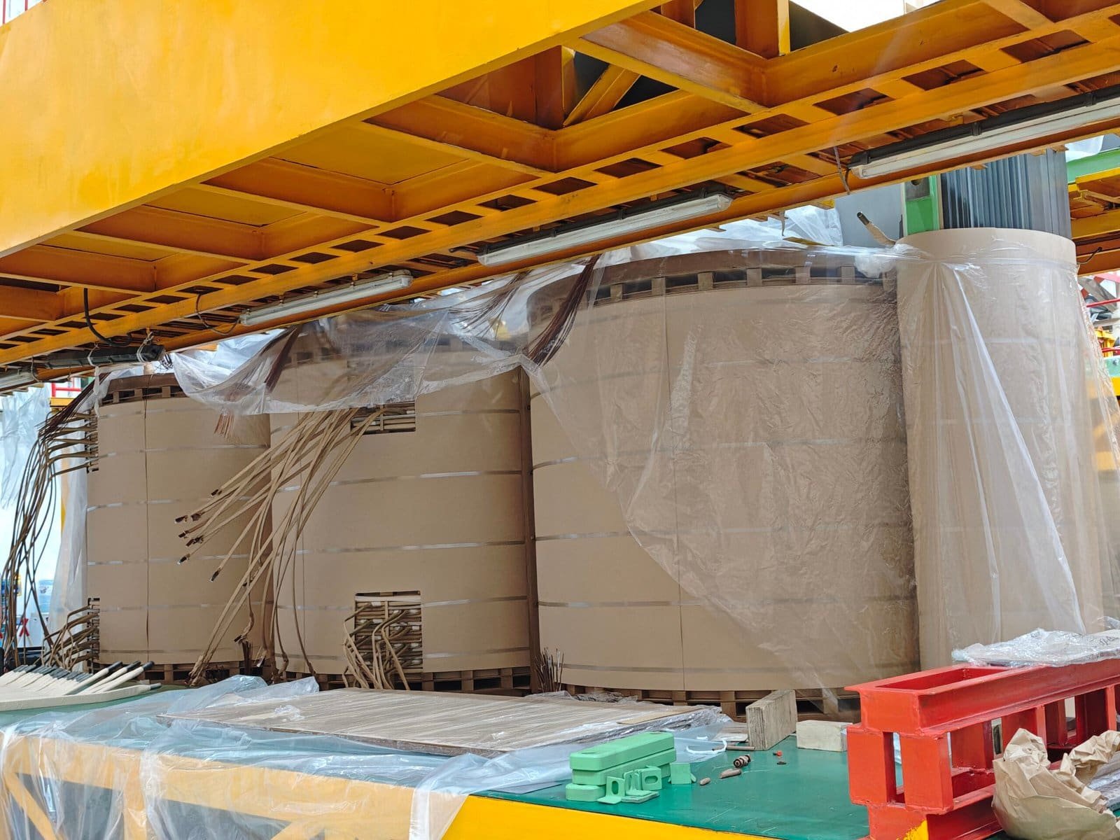
Power transformer winding design is one of the most important factors influencing transformer efficiency, reliability, mechanical strength, thermal performance, and service life. Although the transformer core provides the magnetic path required for voltage transformation, the windings carry electrical energy and directly experience thermal stress, electromagnetic forces, and insulation stress during operation. Poor winding design can lead to overheating, excessive losses, insulation aging, mechanical deformation, and premature transformer failure. Advanced winding designs, optimized conductor arrangements, improved cooling channels, and stronger mechanical structures allow manufacturers to build transformers that operate safely under demanding electrical conditions.
Winding designs affect power transformer performance by determining electrical losses, voltage regulation, short-circuit strength, cooling efficiency, insulation reliability, and resistance to mechanical forces. Engineers optimize winding structure, conductor arrangement, insulation systems, and mechanical support to reduce losses, control temperature rise, improve fault withstand capability, and extend transformer service life.
Transformer winding design has little influence on performance because the transformer core determines most operating characteristics.False
Winding design strongly affects transformer losses, thermal behavior, voltage regulation, mechanical strength, insulation performance, and reliability during normal and fault conditions.
Why are transformer windings critical to transformer performance?
Transformer windings are conductive coils that transfer electrical energy through electromagnetic induction. They are responsible for:
- Carrying load current
- Producing magnetic coupling with the core
- Maintaining voltage transformation
- Withstanding electrical and mechanical stress
The winding system must operate reliably under:
- Continuous rated load
- Short-term overload
- Short-circuit conditions
- Voltage fluctuations
- Thermal cycling
A transformer with a high-quality winding design can achieve:
- Lower losses
- Better efficiency
- Improved cooling
- Longer insulation life
- Higher fault resistance
| Winding Design Factor | Performance Impact |
|---|---|
| Conductor arrangement | Determines losses |
| Insulation structure | Determines dielectric reliability |
| Mechanical support | Determines fault withstand strength |
| Cooling channels | Determines temperature control |
How does winding design influence transformer efficiency?
Transformer efficiency is strongly affected by winding resistance and conductor losses.
The primary source of winding-related losses is copper loss, which occurs when current flows through conductors.
Factors affecting copper loss include:
- Conductor material
- Conductor cross-sectional area
- Winding length
- Current density
- Operating temperature
A well-designed winding minimizes unnecessary resistance while maintaining mechanical strength.
| Design Approach | Efficiency Effect |
|---|---|
| Larger conductor area | Reduces resistance losses |
| Optimized winding length | Reduces copper consumption |
| Better conductor arrangement | Improves current distribution |
| Lower resistance design | Improves efficiency |
How do different winding types affect transformer performance?
Manufacturers use different winding structures depending on voltage level, power rating, and application requirements.
Common winding types include:
- Layer windings
- Helical windings
- Disc windings
- Continuous disc windings
- Foil windings
Each design provides different advantages.
| Winding Type | Common Application | Main Advantage |
|---|---|---|
| Layer winding | Distribution transformers | Simple construction |
| Helical winding | High-current transformers | Strong mechanical design |
| Disc winding | High-voltage transformers | Excellent voltage distribution |
| Foil winding | Low-voltage high-current units | Reduced leakage effects |
How do disc windings improve high-voltage transformer performance?
Disc windings are widely used in high-voltage power transformers because they provide excellent insulation control.
Disc windings divide the coil into multiple sections separated by insulation barriers.
Advantages include:
- Better impulse voltage distribution
- Improved dielectric strength
- Reduced electrical stress concentration
- Better cooling oil circulation
They are commonly used in:
- Transmission transformers
- Large utility transformers
- Industrial power transformers
How do conductor arrangement and transposition affect transformer losses?
Large transformer windings may experience uneven current distribution due to electromagnetic effects.
These effects include:
- Eddy current losses
- Circulating currents
- Uneven heating
Manufacturers use techniques such as:
- Continuously transposed conductors (CTC)
- Strand transposition
- Optimized conductor placement
These methods help:
- Reduce additional losses
- Improve temperature distribution
- Increase efficiency
| Conductor Technique | Benefit |
|---|---|
| Transposed conductors | Reduce eddy losses |
| Multiple strands | Improve current sharing |
| Optimized placement | Reduce hot spots |
How does winding design affect transformer cooling?
Heat generated inside windings must be effectively removed to maintain safe operating temperatures.
Winding design affects cooling through:
- Oil flow paths
- Cooling duct arrangement
- Conductor spacing
- Heat transfer surfaces
Poor cooling design can create:
- Hot spots
- Accelerated insulation aging
- Reduced loading capability
Engineers optimize:
- Vertical oil channels
- Horizontal cooling ducts
- Winding spacing
| Cooling Feature | Function |
|---|---|
| Oil ducts | Remove heat |
| Proper spacing | Improve circulation |
| Optimized geometry | Reduce hot spots |
How does winding design influence transformer temperature rise?
Temperature rise is one of the most important transformer design parameters.
Higher temperatures accelerate insulation aging.
Winding design affects:
- Average winding temperature
- Hot spot temperature
- Thermal gradients
A well-designed winding ensures:
- Uniform heat distribution
- Effective cooling
- Lower insulation stress
| Thermal Issue | Winding Design Solution |
|---|---|
| Hot spots | Improve oil circulation |
| High resistance loss | Increase conductor efficiency |
| Uneven heating | Optimize conductor arrangement |
How do winding designs improve short-circuit withstand capability?
Short circuits create extremely high currents that generate powerful electromagnetic forces.
These forces can cause:
- Axial movement
- Radial deformation
- Conductor displacement
- Insulation damage
A transformer winding must withstand these forces without permanent deformation.
Manufacturers improve mechanical strength through:
- Strong clamping structures
- Reinforced insulation blocks
- Optimized winding geometry
- High-strength conductors
| Mechanical Feature | Benefit |
|---|---|
| Strong clamping | Prevents movement |
| Rigid winding structure | Improves fault resistance |
| Reinforced insulation | Supports conductors |
How do electromagnetic forces affect transformer windings?
During short circuits, electromagnetic forces increase rapidly.
The forces depend on:
- Fault current magnitude
- Winding geometry
- Leakage flux distribution
High forces may cause:
- Compression stress
- Tensile stress
- Bending forces
Engineers use advanced design calculations and simulations to predict these stresses.
How does winding design affect voltage regulation?
Voltage regulation describes how transformer output voltage changes with load.
Winding characteristics influencing voltage regulation include:
- Resistance
- Leakage reactance
- Winding arrangement
A well-designed winding reduces unwanted voltage variation.
| Winding Parameter | Voltage Regulation Effect |
|---|---|
| Lower resistance | Reduced voltage drop |
| Controlled leakage reactance | Improved regulation |
| Optimized geometry | Better performance |
How does leakage reactance depend on winding design?
Leakage reactance occurs because not all magnetic flux links both windings.
It is influenced by:
- Distance between windings
- Winding height
- Radial arrangement
- Axial positioning
Proper control is necessary because:
- Too much leakage reactance reduces voltage regulation.
- Too little leakage reactance may increase short-circuit stress.
Engineers optimize winding geometry to achieve the correct balance.
How does insulation design within windings improve reliability?
Winding insulation prevents electrical breakdown between:
- Turns
- Layers
- Windings
- Grounded components
Insulation design includes:
- Paper insulation
- Pressboard barriers
- Oil insulation
- Epoxy materials
Important considerations include:
- Voltage stress distribution
- Impulse withstand capability
- Aging resistance
| Insulation Component | Function |
|---|---|
| Turn insulation | Prevent turn-to-turn faults |
| Layer insulation | Separate winding sections |
| Main insulation | Isolate high-voltage parts |
| Pressboard structures | Provide mechanical support |
How do manufacturers test transformer winding quality?
Factory testing verifies winding performance before shipment.
Important tests include:
| Test | Purpose |
|---|---|
| Winding resistance test | Verify conductor integrity |
| Impedance test | Confirm winding characteristics |
| Insulation test | Verify dielectric strength |
| Partial discharge test | Detect insulation defects |
| Temperature rise test | Verify thermal performance |
These tests confirm that winding design meets technical requirements.
How does winding design affect transformer lifespan?
Transformer lifespan is strongly related to insulation aging.
The winding system influences:
- Operating temperature
- Mechanical stress
- Electrical stress
A high-quality winding design reduces:
- Thermal degradation
- Mechanical damage
- Insulation breakdown
| Design Improvement | Lifespan Benefit |
|---|---|
| Better cooling | Slower insulation aging |
| Stronger structure | Higher fault resistance |
| Improved insulation | Longer dielectric life |
| Lower losses | Reduced thermal stress |
What winding design considerations are important for different applications?
Different transformer applications require different winding solutions.
| Application | Key Winding Requirement |
|---|---|
| Utility transformers | High short-circuit strength |
| Industrial transformers | Strong overload capability |
| Renewable energy transformers | Variable load performance |
| Data center transformers | High reliability |
| Distribution transformers | Cost efficiency |
How do advanced simulation tools improve winding design?
Modern transformer manufacturers use:
- Electromagnetic simulation
- Thermal analysis
- Mechanical stress modeling
- Computational fluid dynamics
These tools help optimize:
- Magnetic field distribution
- Temperature performance
- Mechanical strength
- Material usage
Simulation reduces design risks before manufacturing begins.
How should buyers evaluate transformer winding design?
When purchasing a power transformer, buyers should ask manufacturers about:
| Evaluation Item | Why It Matters |
|---|---|
| Winding type | Determines application suitability |
| Conductor design | Affects losses |
| Short-circuit capability | Ensures mechanical reliability |
| Cooling design | Controls temperature |
| Factory testing | Verifies quality |
Buyers should consider winding design as a key indicator of transformer quality.
How do international standards support winding design quality?
Power transformer winding design and testing commonly follow international standards from:
- International Electrotechnical Commission
- Institute of Electrical and Electronics Engineers
These standards provide guidance for:
- Transformer construction
- Insulation coordination
- Short-circuit withstand testing
- Performance verification
Compliance helps ensure reliable transformer operation.
What Types of Winding Designs Are Used in Power Transformers?
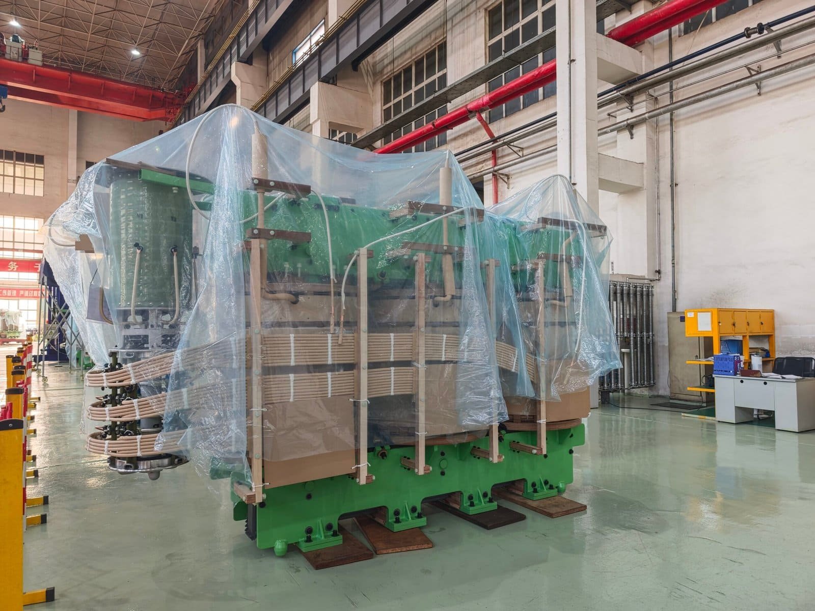
Power transformer winding design plays a fundamental role in determining electrical performance, efficiency, mechanical strength, thermal behavior, and long-term reliability. The winding system is responsible for carrying current and transferring electrical energy between circuits through electromagnetic induction, which means its structure must withstand continuous operating stress as well as abnormal conditions such as short circuits and voltage surges. Different transformer applications require different winding designs because voltage level, current capacity, power rating, insulation requirements, and mechanical strength demands vary significantly. Understanding the main types of power transformer winding designs helps engineers, buyers, and operators select equipment that provides reliable performance throughout its service life.
The main types of winding designs used in power transformers include layer windings, helical windings, disc windings, continuous disc windings, foil windings, and interleaved windings. Each design has specific advantages: layer windings are commonly used for lower-voltage applications, helical windings are suitable for high-current transformers, disc windings provide excellent insulation control for high-voltage transformers, continuous disc windings improve voltage distribution, foil windings support compact low-voltage high-current designs, and interleaved windings enhance impulse voltage performance.
Disc windings are used only in small distribution transformers because they cannot withstand high-voltage applications.False
Disc windings are widely used in high-voltage and large power transformers because they provide excellent voltage distribution, insulation control, and impulse withstand capability.
Why is winding design important in power transformers?
The winding assembly is one of the most critical components inside a power transformer. While the core provides the magnetic path, the windings directly handle electrical energy transfer and experience many operational stresses.
A properly designed winding must achieve:
- Low electrical losses
- Effective heat dissipation
- High insulation strength
- Strong short-circuit resistance
- Stable voltage regulation
- Long service life
Poor winding design can lead to:
- Excessive copper losses
- High temperature rise
- Insulation deterioration
- Mechanical deformation
- Internal faults
| Winding Design Requirement | Performance Impact |
|---|---|
| Low resistance | Improves efficiency |
| Strong mechanical support | Improves fault withstand capability |
| Optimized insulation | Prevents electrical breakdown |
| Good cooling channels | Reduces overheating |
What factors determine the selection of transformer winding design?
Manufacturers select winding structures based on several technical parameters.
Important factors include:
- Rated voltage
- Rated current
- Transformer capacity
- Frequency
- Short-circuit requirements
- Cooling method
- Insulation level
- Manufacturing limitations
For example:
A high-voltage transmission transformer requires excellent insulation distribution, while a low-voltage high-current transformer requires strong current-carrying capability and efficient heat removal.
| Application Requirement | Preferred Winding Consideration |
|---|---|
| High voltage | Strong insulation design |
| High current | Low resistance structure |
| High short-circuit level | Strong mechanical support |
| Compact design | Optimized conductor arrangement |
What Is a Layer Winding Design?
Layer winding is one of the simplest and most economical transformer winding structures. In this design, insulated conductors are arranged in multiple layers along the winding axis.
Layer windings are commonly used in:
- Small distribution transformers
- Control transformers
- Low-power transformers
The main characteristics include:
- Simple manufacturing process
- Low production cost
- Compact structure
- Easy insulation arrangement
However, layer windings have limitations for high-voltage applications because voltage distribution between layers becomes more difficult as voltage increases.
| Feature | Layer Winding |
|---|---|
| Manufacturing complexity | Low |
| Cost | Low |
| Voltage application | Low to medium |
| Current capability | Moderate |
| Common use | Distribution transformers |
Advantages of layer windings
Layer windings provide several benefits:
- Simple construction
The winding process is relatively straightforward, reducing manufacturing complexity.
- Cost efficiency
The design requires fewer specialized manufacturing processes.
- Compact structure
Layer arrangements can achieve efficient space utilization in smaller transformers.
Limitations of layer windings
Despite their advantages, layer windings are less suitable for large high-voltage transformers because:
- Electric stress between layers increases
- Impulse voltage distribution becomes more challenging
- Cooling performance may be limited
What Is a Helical Winding Design?
Helical windings are designed primarily for applications requiring high current capacity.
In a helical winding, conductors are arranged in a spiral pattern around the transformer core.
They are commonly used in:
- Low-voltage high-current windings
- Large industrial transformers
- Generator transformers
Helical winding designs provide:
- Large conductor cross-sectional area
- Good mechanical strength
- Efficient current distribution
| Feature | Helical Winding |
|---|---|
| Current capability | Very high |
| Mechanical strength | High |
| Voltage application | Low to medium |
| Manufacturing complexity | Medium |
Why are helical windings suitable for high-current transformers?
High-current transformers require conductors capable of carrying large electrical currents without excessive heating.
Helical windings provide:
- Short current paths
- Reduced conductor resistance
- Strong structural support
They are especially useful where:
- Current is high
- Voltage is relatively lower
- Mechanical strength is important
How do helical windings improve mechanical strength?
During short circuits, electromagnetic forces can create large mechanical stresses.
Helical windings resist these forces through:
- Strong conductor arrangement
- Continuous winding support
- Improved axial strength
This makes them suitable for demanding industrial applications.
What Is a Disc Winding Design?
Disc winding is one of the most widely used winding designs for high-voltage power transformers.
In this structure, the winding is divided into multiple disc-shaped sections connected electrically in series.
Disc windings are commonly used in:
- Transmission transformers
- Large utility transformers
- High-voltage industrial transformers
Their main advantage is excellent control of voltage distribution.
| Feature | Disc Winding |
|---|---|
| Voltage capability | High |
| Insulation performance | Excellent |
| Mechanical strength | High |
| Application | Large power transformers |
Why are disc windings preferred for high-voltage transformers?
High-voltage transformers experience significant electrical stress during:
- Normal operation
- Switching events
- Lightning impulses
Disc windings improve reliability by:
- Distributing voltage evenly
- Reducing electrical stress concentration
- Improving impulse withstand capability
What are continuous disc windings?
Continuous disc windings are an advanced form of disc winding technology.
They consist of multiple discs connected continuously with optimized conductor paths.
Advantages include:
- Improved mechanical strength
- Better voltage distribution
- Reduced circulating losses
- Higher reliability
They are commonly used in:
- Large oil-immersed power transformers
- Utility transmission equipment
| Design Feature | Benefit |
|---|---|
| Continuous conductor path | Reduced connection points |
| Disc structure | Improved insulation |
| Strong support | Better short-circuit resistance |
What Is a Foil Winding Design?
Foil windings use wide, thin conductive sheets instead of round wire conductors.
They are commonly used in:
- Low-voltage transformers
- Dry-type transformers
- Compact power supplies
The foil conductor provides:
- Uniform current distribution
- Reduced leakage effects
- Compact construction
| Feature | Foil Winding |
|---|---|
| Current distribution | Excellent |
| Manufacturing speed | High |
| Voltage capability | Low to medium |
| Common application | Low-voltage transformers |
What are the advantages of foil windings?
Foil windings offer several benefits:
- Reduced winding height
- Better conductor utilization
- Lower leakage flux effects
- Improved mechanical stability
They are especially effective when:
- Current is high
- Voltage is relatively low
- Space is limited
What Is an Interleaved Winding Design?
Interleaved windings are designed to improve impulse voltage performance.
In this arrangement, winding sections are specially arranged to control voltage distribution during transient events.
They are used in applications requiring high dielectric strength.
Advantages include:
- Improved lightning impulse performance
- Reduced turn-to-turn voltage stress
- Better insulation coordination
| Feature | Interleaved Winding |
|---|---|
| Impulse performance | Excellent |
| Manufacturing complexity | Higher |
| Application | High-voltage transformers |
How do different winding designs compare?
| Winding Type | Voltage Range | Current Capability | Main Advantage | Typical Application |
|---|---|---|---|---|
| Layer winding | Low-medium | Medium | Simple and economical | Distribution transformers |
| Helical winding | Low-medium | High | Strong current capability | Industrial transformers |
| Disc winding | High | Medium-high | Excellent insulation control | Utility transformers |
| Continuous disc winding | High | High | Mechanical reliability | Large power transformers |
| Foil winding | Low | High | Compact structure | Low-voltage transformers |
| Interleaved winding | High | Medium | Strong impulse performance | High-voltage transformers |
How do winding designs affect transformer reliability?
Different winding structures influence major reliability factors.
Thermal performance
Winding design determines:
- Heat generation
- Oil circulation
- Temperature distribution
Better cooling reduces insulation aging.
Mechanical strength
A strong winding structure helps resist:
- Short-circuit forces
- Vibration
- Transportation stress
Electrical performance
Winding arrangement affects:
- Leakage reactance
- Voltage regulation
- Impulse withstand capability
Service life
A well-designed winding reduces:
- Thermal stress
- Electrical stress
- Mechanical damage
| Reliability Factor | Winding Design Influence |
|---|---|
| Insulation life | Controls electrical stress |
| Cooling performance | Controls temperature |
| Fault resistance | Controls mechanical strength |
| Efficiency | Controls losses |
How are winding designs tested during transformer manufacturing?
Manufacturers perform multiple tests to verify winding quality.
Common tests include:
| Test | Purpose |
|---|---|
| Winding resistance test | Verify conductor quality |
| Impedance test | Confirm winding characteristics |
| Short-circuit test | Verify mechanical strength |
| Insulation test | Confirm dielectric performance |
| Temperature rise test | Verify thermal design |
These tests ensure the winding design meets required standards.
How should buyers evaluate transformer winding design?
Before purchasing a power transformer, buyers should consider:
- Transformer application
- Voltage level
- Load characteristics
- Short-circuit requirements
- Expected service life
Important questions include:
| Buyer Question | Purpose |
|---|---|
| What winding type is used? | Confirm application suitability |
| What conductor technology is applied? | Evaluate efficiency |
| How is short-circuit strength achieved? | Assess reliability |
| What tests verify winding quality? | Confirm manufacturing capability |
How do international standards influence winding design?
Power transformer winding design and testing commonly follow standards from:
- International Electrotechnical Commission
- Institute of Electrical and Electronics Engineers
These standards define requirements for:
- Transformer performance
- Insulation coordination
- Short-circuit withstand capability
- Factory testing procedures
Compliance with recognized standards helps ensure that winding designs meet international reliability expectations.
How Does Winding Design Influence Transformer Efficiency and Energy Losses?
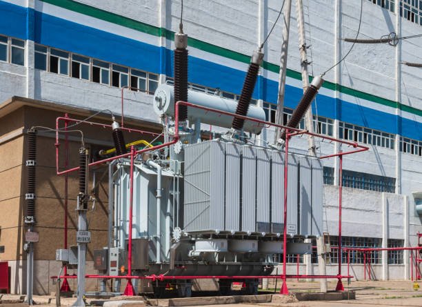
Power transformer efficiency is closely related to winding design because the windings are responsible for carrying electrical current and transferring energy between circuits. Although transformer cores determine magnetic performance, winding structures directly influence copper losses, stray losses, temperature rise, voltage regulation, and overall operating costs. Poorly designed windings can increase electrical resistance, create uneven current distribution, generate excessive heat, and accelerate insulation aging. Advanced winding designs help manufacturers reduce energy losses, improve thermal performance, and achieve higher efficiency throughout the transformer’s service life.
Winding design influences transformer efficiency and energy losses by controlling conductor resistance, current distribution, eddy current effects, leakage flux, cooling performance, and mechanical stability. Optimized winding designs use appropriate conductor sizes, transposed conductors, improved winding arrangements, and effective cooling channels to reduce copper losses, minimize stray losses, lower operating temperatures, and improve total transformer efficiency.
Transformer winding design mainly affects mechanical strength and has little influence on transformer energy efficiency.False
Winding design directly affects conductor resistance, copper losses, stray losses, heat generation, and therefore the overall efficiency of power transformers.
Why does winding design affect transformer efficiency?
Transformer efficiency represents how effectively electrical input power is converted into useful output power.
Energy losses inside a transformer mainly come from:
- Core losses
- Winding copper losses
- Stray load losses
- Dielectric losses
- Mechanical and auxiliary losses
Among these losses, winding-related losses can represent a significant portion, especially when the transformer operates under heavy load.
A winding design determines:
- Electrical resistance
- Current density
- Heat generation
- Magnetic leakage behavior
- Cooling efficiency
| Winding Parameter | Effect on Efficiency |
|---|---|
| Conductor size | Determines resistance losses |
| Current density | Controls heat generation |
| Winding arrangement | Influences stray losses |
| Cooling design | Affects operating temperature |
How do winding resistance and copper losses affect transformer performance?
The largest winding-related energy loss is copper loss, which occurs because conductors have electrical resistance.
Copper loss increases according to:
where higher resistance and higher current create greater heat generation.
Winding resistance depends on:
- Conductor material
- Conductor length
- Cross-sectional area
- Operating temperature
- Winding arrangement
A well-designed winding reduces resistance by:
- Increasing conductor cross-sectional area
- Optimizing conductor length
- Using high-quality copper or aluminum conductors
- Improving conductor arrangement
| Design Improvement | Impact on Copper Loss |
|---|---|
| Larger conductor area | Lower resistance |
| Shorter current path | Reduced losses |
| Better conductor material | Improved conductivity |
| Optimized winding geometry | Better efficiency |
How does conductor size influence transformer energy losses?
The size of the winding conductor is one of the most important efficiency factors.
If the conductor is too small:
- Resistance increases
- Copper losses increase
- Temperature rises
- Insulation aging accelerates
If the conductor is appropriately sized:
- Current density decreases
- Heat generation is reduced
- Efficiency improves
Manufacturers select conductor dimensions based on:
- Rated current
- Cooling method
- Transformer capacity
- Temperature limits
| Conductor Design | Efficiency Result |
|---|---|
| Undersized conductor | Higher losses |
| Optimized conductor | Lower losses |
| Oversized conductor | Lower losses but higher material cost |
How does current density affect transformer efficiency?
Current density describes how much current flows through a conductor area.
High current density causes:
- Increased copper losses
- Higher winding temperature
- Reduced insulation life
Low current density improves:
- Thermal performance
- Reliability
- Efficiency
However, excessively reducing current density increases:
- Transformer size
- Material consumption
- Manufacturing cost
Engineers must balance efficiency and economic design.
| Current Density Level | Effect |
|---|---|
| Too high | Excess heating |
| Optimized | Best efficiency |
| Too low | Larger and more expensive transformer |
How do winding arrangements reduce energy losses?
Different winding structures affect how electrical current and magnetic fields interact.
Common winding arrangements include:
- Layer windings
- Helical windings
- Disc windings
- Continuous disc windings
- Foil windings
Each design provides different efficiency characteristics.
| Winding Type | Efficiency Advantage |
|---|---|
| Helical winding | Suitable for high current with low resistance |
| Disc winding | Good voltage distribution and reduced losses |
| Foil winding | Uniform current distribution |
| Continuous disc winding | Reduced circulating losses |
How do continuously transposed conductors improve efficiency?
Large power transformer windings often use continuously transposed conductors (CTC) to reduce additional losses.
Large conductors can experience uneven current distribution due to electromagnetic effects.
This can create:
- Eddy current losses
- Circulating currents
- Uneven heating
CTC technology improves performance by:
- Transposing conductor strands
- Equalizing magnetic exposure
- Reducing circulating currents
| CTC Benefit | Result |
|---|---|
| Better current sharing | Lower losses |
| Reduced eddy currents | Improved efficiency |
| More uniform heating | Better reliability |
How do eddy currents increase transformer losses?
Eddy currents are unwanted circulating currents generated by changing magnetic fields.
In transformer windings, they can occur because:
- Conductors are exposed to leakage flux
- Large conductors create internal current loops
- Magnetic fields are uneven
Eddy current losses cause:
- Additional heating
- Reduced efficiency
- Increased thermal stress
Manufacturers reduce these losses through:
- Strand transposition
- Proper conductor positioning
- Optimized winding geometry
How does leakage flux influence winding losses?
Not all magnetic flux produced by one winding links perfectly with the other winding.
The unlinked portion is leakage flux.
Leakage flux can create:
- Stray losses
- Additional conductor heating
- Uneven temperature distribution
Winding design controls leakage flux through:
- Proper winding spacing
- Optimized radial arrangement
- Balanced winding geometry
| Leakage Flux Control Method | Benefit |
|---|---|
| Optimized winding position | Reduced stray losses |
| Proper spacing | Better magnetic balance |
| Improved geometry | Lower heating |
How does winding cooling design improve efficiency?
Energy losses eventually become heat, so efficient cooling is essential.
Winding design affects:
- Oil circulation
- Heat transfer
- Hot spot temperature
Common cooling improvements include:
- Radial cooling ducts
- Axial oil channels
- Optimized conductor spacing
Better cooling provides:
- Lower operating temperature
- Reduced insulation stress
- Higher allowable loading
| Cooling Feature | Efficiency Benefit |
|---|---|
| Oil channels | Removes heat |
| Proper spacing | Improves circulation |
| Thermal optimization | Reduces aging |
How does temperature affect transformer energy losses?
Winding resistance increases as temperature rises.
Higher temperature causes:
- Increased copper losses
- Reduced efficiency
- Faster insulation degradation
A transformer operating at high temperature experiences:
- Greater energy waste
- Shorter service life
- Higher maintenance requirements
Good winding design maintains acceptable temperatures by balancing:
- Electrical loading
- Heat generation
- Cooling capability
How do winding designs affect transformer load efficiency?
Transformer efficiency changes depending on load level.
At low load:
- Core losses dominate
At high load:
- Copper losses become more significant
Therefore, winding design is especially important for:
- Industrial transformers
- Renewable energy transformers
- Utility transformers
| Load Condition | Main Loss Concern |
|---|---|
| No load | Core losses |
| Medium load | Balanced losses |
| Full load | Copper losses |
How do winding designs improve voltage regulation?
Winding design also affects voltage regulation, which influences system performance.
Important factors include:
- Winding resistance
- Leakage reactance
- Winding arrangement
Better winding design helps maintain stable output voltage.
Advantages include:
- Reduced voltage drop
- Improved power quality
- Better equipment performance
How do manufacturers optimize winding design for energy efficiency?
Modern transformer manufacturers use advanced engineering methods, including:
- Electromagnetic simulation
- Thermal modeling
- Finite element analysis
- Computational fluid dynamics
These tools help optimize:
- Conductor arrangement
- Magnetic field distribution
- Cooling paths
- Loss performance
| Optimization Method | Purpose |
|---|---|
| Electromagnetic simulation | Reduce stray losses |
| Thermal simulation | Control temperature |
| Mechanical analysis | Improve reliability |
| Material optimization | Reduce losses |
What tests verify transformer winding efficiency performance?
Manufacturers perform factory tests to confirm winding performance.
Important tests include:
| Test | Purpose |
|---|---|
| Winding resistance test | Measure conductor resistance |
| Load loss test | Verify copper losses |
| Temperature rise test | Confirm thermal performance |
| Impedance test | Evaluate winding characteristics |
| Efficiency calculation | Confirm performance |
These tests verify that the transformer meets design expectations.
How should buyers evaluate winding design when purchasing transformers?
Buyers should consider winding design as an important indicator of transformer quality.
Key questions include:
| Buyer Question | Importance |
|---|---|
| What winding type is used? | Determines suitability |
| What conductor technology is applied? | Affects losses |
| How are stray losses controlled? | Improves efficiency |
| What efficiency tests are performed? | Confirms performance |
Buyers should evaluate both initial purchase cost and long-term energy costs.
How do energy-efficient winding designs reduce lifecycle costs?
A transformer operates for decades, so even small efficiency improvements can produce significant savings.
Benefits include:
- Lower electricity losses
- Reduced operating costs
- Less cooling demand
- Longer insulation life
For large transformers, reduced losses can save substantial energy costs over the equipment lifecycle.
| Efficiency Improvement | Long-Term Benefit |
|---|---|
| Reduced copper loss | Lower electricity waste |
| Better cooling | Longer service life |
| Lower temperature | Reduced maintenance |
| Optimized design | Higher reliability |
How do international standards support transformer efficiency design?
Power transformer efficiency and loss evaluation commonly follow international standards from:
- International Electrotechnical Commission
- Institute of Electrical and Electronics Engineers
These standards define requirements for:
- Transformer losses
- Efficiency evaluation
- Testing procedures
- Performance verification
Compliance ensures that transformer winding designs meet recognized technical requirements.
Why Is Mechanical Strength Important in Power Transformer Windings?
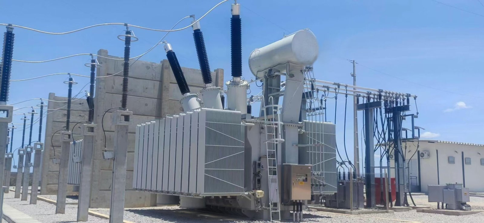
Power transformer windings are exposed to some of the highest mechanical stresses within the transformer during operation, especially when short-circuit faults occur. Although windings are primarily designed to conduct electrical current and transfer energy, they must also withstand powerful electromagnetic forces, thermal expansion, vibration, and transportation impacts without deformation. Insufficient mechanical strength can cause winding displacement, insulation damage, internal faults, and catastrophic transformer failure. Therefore, mechanical strength is a critical design requirement that directly affects transformer reliability, safety, and service life.
Mechanical strength is important in power transformer windings because it enables the windings to withstand short-circuit electromagnetic forces, mechanical vibration, thermal expansion, and operational stresses without deformation. Strong winding structures maintain conductor alignment, protect insulation systems, prevent internal failures, and ensure reliable transformer operation throughout the equipment’s service life.
Transformer windings only need electrical insulation because mechanical forces inside transformers are too small to cause damage.False
Transformer windings experience significant electromagnetic forces during short circuits and must be mechanically reinforced to prevent deformation and insulation failure.
Why do transformer windings experience mechanical stress?
Transformer windings operate under continuous electrical and environmental conditions that create mechanical stress.
The main sources of mechanical stress include:
- Short-circuit electromagnetic forces
- Thermal expansion and contraction
- Electromagnetic vibration
- Transportation shocks
- Manufacturing tolerances
During normal operation, these forces are usually manageable. However, during a short circuit, current can increase many times above rated levels, producing extremely high electromagnetic forces.
| Stress Source | Effect on Windings |
|---|---|
| Short-circuit current | Creates strong mechanical forces |
| Thermal cycling | Causes expansion and contraction |
| Vibration | Produces fatigue over time |
| Transportation impact | May loosen structures |
How do short circuits affect transformer winding mechanical strength?
Short-circuit events are the most severe mechanical challenge for transformer windings.
When a short circuit occurs:
- Current increases dramatically.
- Magnetic fields around conductors become stronger.
- Electromagnetic forces act on the windings.
- Conductors experience compression, tension, and bending forces.
The resulting forces can cause:
- Radial deformation
- Axial movement
- Conductor buckling
- Insulation damage
Although electromagnetic force calculations in transformers are more complex than point-charge interactions, the principle remains that electromagnetic forces increase rapidly as electrical conditions become more severe.
Why are short-circuit withstand capabilities important?
A power transformer may experience short circuits caused by:
- Grid faults
- Equipment failures
- Lightning-related events
- Switching problems
The transformer must survive these events without permanent damage.
A mechanically strong winding allows:
- Safe fault current handling
- Minimal conductor movement
- Preservation of insulation integrity
- Faster return to service
| Short-Circuit Requirement | Mechanical Design Solution |
|---|---|
| High radial forces | Strong conductor support |
| Axial compression | Reinforced clamping system |
| Winding movement prevention | Rigid winding structure |
How do electromagnetic forces deform transformer windings?
Electromagnetic forces inside transformers generally act in two major directions:
Radial forces
Radial forces push conductors inward or outward.
Potential problems include:
- Conductor distortion
- Insulation compression
- Winding instability
Axial forces
Axial forces push winding sections vertically along the transformer axis.
Potential problems include:
- Winding displacement
- Clamping failure
- Insulation damage
| Force Direction | Main Risk |
|---|---|
| Radial | Buckling and deformation |
| Axial | Movement and collapse |
How do winding designs improve mechanical strength?
Manufacturers improve winding strength through careful structural design.
Important methods include:
- Optimized winding geometry
- Strong mechanical clamping
- Reinforced insulation materials
- High-strength conductors
- Controlled manufacturing processes
Common mechanical reinforcement features include:
- Press rings
- Spacer blocks
- Axial supports
- Radial supports
| Design Feature | Function |
|---|---|
| Clamping structures | Prevent movement |
| Insulation blocks | Support conductors |
| Strong conductors | Resist deformation |
| Precision assembly | Maintain alignment |
How does conductor arrangement influence winding strength?
The arrangement of conductors inside the winding affects how forces are distributed.
Poor conductor arrangement can create:
- Uneven force concentration
- Localized stress points
- Weak mechanical areas
Optimized arrangements provide:
- Better force distribution
- Improved stability
- Reduced deformation risk
Examples include:
- Disc winding structures
- Helical winding structures
- Continuously transposed conductors
| Conductor Arrangement | Mechanical Benefit |
|---|---|
| Disc winding | Strong axial support |
| Helical winding | High current mechanical stability |
| CTC conductors | Improved force distribution |
Why are disc windings mechanically strong?
Disc windings are widely used in high-voltage power transformers because they provide excellent mechanical performance.
Their advantages include:
- Strong structural arrangement
- Good axial stability
- Effective force distribution
- High insulation support
Disc windings divide the winding into multiple sections, allowing manufacturers to control:
- Electrical stress
- Mechanical forces
- Cooling paths
They are commonly used in:
- Transmission transformers
- Large utility transformers
- High-voltage industrial transformers
How do clamping systems improve transformer winding reliability?
Clamping systems maintain the mechanical position of windings.
They prevent:
- Movement during faults
- Loosening over time
- Damage caused by vibration
A good clamping system provides:
- Proper compression pressure
- Stable winding positioning
- Long-term mechanical support
However, excessive clamping pressure can also damage insulation, so manufacturers must carefully optimize the design.
| Clamping Condition | Result |
|---|---|
| Too loose | Winding movement |
| Optimized | Maximum reliability |
| Too tight | Insulation damage risk |
How does insulation contribute to mechanical strength?
Transformer insulation materials do more than provide electrical isolation.
Materials such as:
- Pressboard
- Kraft paper
- Laminated insulation blocks
also provide mechanical support.
They help:
- Maintain conductor spacing
- Absorb mechanical forces
- Prevent movement between winding sections
| Insulation Material | Mechanical Function |
|---|---|
| Pressboard | Structural support |
| Paper insulation | Turn separation |
| Spacer blocks | Maintain winding geometry |
How does thermal expansion affect winding mechanical strength?
Transformer windings heat up during operation and expand.
Temperature changes cause:
- Conductor expansion
- Insulation expansion
- Mechanical stress cycles
Repeated thermal cycling can lead to:
- Material fatigue
- Reduced clamping force
- Winding looseness
A strong winding design considers:
- Expansion allowance
- Material compatibility
- Long-term mechanical stability
How does vibration influence transformer winding life?
Transformers experience vibration from:
- Magnetic forces
- Core vibration
- Cooling equipment
- External mechanical sources
Long-term vibration may cause:
- Loose connections
- Insulation wear
- Mechanical fatigue
Strong winding structures minimize these effects by maintaining rigid support.
How do manufacturers test winding mechanical strength?
Manufacturers verify mechanical performance through multiple tests.
Important tests include:
| Test | Purpose |
|---|---|
| Short-circuit withstand test | Verify fault resistance |
| Impulse test | Evaluate insulation coordination |
| Vibration inspection | Check mechanical stability |
| Winding resistance measurement | Detect deformation |
| Frequency response analysis (FRA) | Identify winding movement |
What is frequency response analysis (FRA) and why is it useful?
Frequency response analysis is a diagnostic method used to detect winding deformation.
It compares the transformer’s electrical response before and after events such as:
- Short circuits
- Transportation
- Severe faults
Changes in response patterns may indicate:
- Winding displacement
- Structural damage
- Mechanical changes
FRA is especially valuable for large transformers where internal inspection is difficult.
How does mechanical strength affect transformer service life?
A mechanically strong winding extends transformer lifespan by preventing:
- Repeated deformation
- Insulation breakdown
- Internal short circuits
Long-term benefits include:
- Higher reliability
- Reduced maintenance requirements
- Lower failure risk
| Mechanical Improvement | Service Life Benefit |
|---|---|
| Stronger clamping | Prevents movement |
| Better support structures | Reduces fatigue |
| Improved conductor design | Handles faults |
| Better manufacturing control | Improves reliability |
How should buyers evaluate transformer winding mechanical strength?
Before purchasing a power transformer, buyers should evaluate:
- Short-circuit withstand capability
- Winding construction method
- Manufacturing quality
- Testing procedures
- Material selection
Important questions include:
| Buyer Question | Purpose |
|---|---|
| What short-circuit level can the transformer withstand? | Evaluate fault capability |
| What winding structure is used? | Confirm application suitability |
| Are mechanical tests performed? | Verify reliability |
| Is FRA testing available? | Support condition assessment |
How do international standards ensure winding mechanical reliability?
Transformer winding mechanical design and testing commonly follow standards from:
- International Electrotechnical Commission
- Institute of Electrical and Electronics Engineers
These standards provide requirements for:
- Short-circuit withstand capability
- Transformer testing
- Mechanical design verification
- Performance evaluation
Compliance helps ensure transformers can withstand expected operating stresses.
How Do Winding Designs Affect Cooling and Insulation Performance?
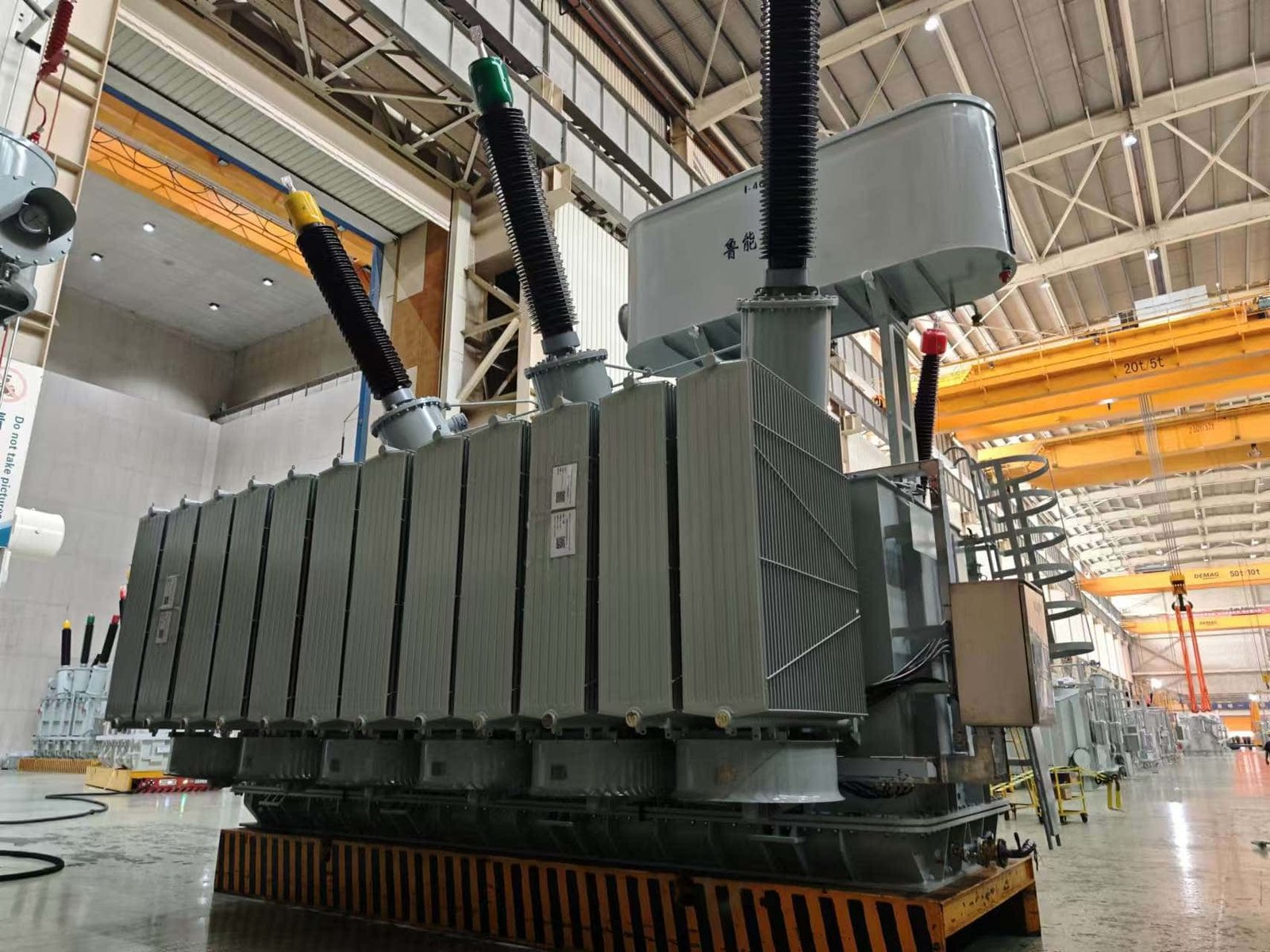
Power transformer winding design has a direct influence on cooling efficiency and insulation reliability because windings are the primary sources of heat generation and electrical stress inside the transformer. During operation, winding conductors produce heat through electrical resistance, while insulation systems must withstand continuous voltage stress, thermal aging, and transient overvoltage conditions. An improper winding structure can create hot spots, uneven oil circulation, excessive temperature rise, and accelerated insulation deterioration. Advanced winding designs optimize conductor arrangement, cooling channels, insulation spacing, and electric field distribution to improve heat dissipation, prevent insulation failures, and extend transformer service life.
Winding designs affect transformer cooling and insulation performance by controlling heat generation, oil flow paths, temperature distribution, electric field stress, and insulation aging rates. Optimized winding structures use proper conductor arrangements, cooling ducts, insulation barriers, and mechanical support systems to reduce hot spots, improve heat transfer, maintain dielectric strength, and increase long-term transformer reliability.
Winding design only affects electrical performance and has no significant impact on transformer cooling or insulation life.False
Winding design directly determines heat generation, cooling efficiency, temperature distribution, electric field stress, and insulation aging performance.
Why are winding designs important for transformer cooling and insulation?
The winding system performs two critical functions:
- Transfers electrical energy through electromagnetic induction.
- Maintains safe operating conditions by managing heat and electrical stress.
During operation, windings experience:
- Copper losses
- Thermal expansion
- Electrical voltage stress
- Insulation aging
- Cooling fluid movement
The winding structure determines how effectively these stresses are controlled.
| Winding Design Factor | Cooling Impact | Insulation Impact |
|---|---|---|
| Conductor arrangement | Controls heat generation | Influences electric stress |
| Cooling ducts | Improves heat removal | Reduces thermal aging |
| Insulation spacing | Affects oil circulation | Improves dielectric strength |
| Winding geometry | Controls temperature distribution | Reduces stress concentration |
How does winding design influence transformer heat generation?
The first step in effective cooling design is reducing unnecessary heat generation.
Winding losses mainly come from:
- DC resistance losses
- Eddy current losses
- Circulating current losses
- Stray load losses
These losses convert electrical energy into heat.
Poor winding designs may cause:
- High current density
- Uneven current distribution
- Excessive conductor temperature
Advanced designs reduce losses through:
- Optimized conductor dimensions
- Proper strand arrangement
- Transposed conductors
- Improved winding geometry
| Heat Generation Source | Winding Design Solution |
|---|---|
| High resistance loss | Larger conductor area |
| Eddy current loss | Strand transposition |
| Uneven heating | Improved conductor layout |
| High current density | Optimized conductor selection |
How do winding structures improve transformer oil circulation?
In oil-immersed power transformers, cooling depends heavily on oil movement through winding channels.
The winding design determines:
- Oil flow direction
- Flow resistance
- Heat transfer efficiency
- Temperature distribution
Common cooling features include:
- Axial cooling ducts
- Radial cooling ducts
- Oil circulation channels
- Directed oil flow structures
A well-designed winding allows cooling oil to pass evenly through the hottest areas.
| Cooling Structure | Function |
|---|---|
| Axial ducts | Allow vertical oil movement |
| Radial ducts | Remove heat from conductors |
| Directed flow channels | Improve cooling efficiency |
| Optimized spacing | Prevent overheating |
How do winding designs prevent transformer hot spots?
Hot spots are areas where winding temperatures become significantly higher than the average winding temperature.
They are dangerous because insulation aging accelerates rapidly at high temperatures.
Hot spots can be caused by:
- Poor oil circulation
- Uneven conductor loading
- Excessive losses
- Incorrect winding arrangement
Manufacturers reduce hot spots through:
- Improved cooling duct design
- Better conductor positioning
- Thermal simulation
- Optimized winding dimensions
| Hot Spot Problem | Design Solution |
|---|---|
| Uneven temperature | Improve oil distribution |
| Poor cooling path | Add cooling ducts |
| High local losses | Optimize conductors |
How does winding design affect insulation temperature aging?
Transformer insulation life is strongly related to temperature.
Higher temperatures accelerate:
- Paper insulation degradation
- Oil oxidation
- Loss of mechanical strength
Winding design affects insulation aging by controlling:
- Hot spot temperature
- Heat transfer rate
- Thermal stress
A cooler winding system generally provides longer insulation life.
| Temperature Condition | Insulation Effect |
|---|---|
| Low operating temperature | Slow aging |
| Controlled temperature | Longer service life |
| Excessive temperature | Accelerated aging |
How do cooling channels improve insulation reliability?
Cooling channels are not only thermal features; they also protect insulation performance.
Effective cooling channels:
- Reduce conductor temperature
- Limit thermal stress
- Prevent insulation breakdown
- Maintain oil insulation quality
In large power transformers, manufacturers carefully design oil channels between winding sections.
Typical arrangements include:
- Disc winding oil ducts
- Layer winding cooling passages
- Helical winding cooling paths
How do disc windings improve cooling and insulation performance?
Disc windings are widely used in high-voltage power transformers because they provide excellent electrical and thermal control.
Their structure creates:
- Multiple oil flow paths
- Controlled voltage distribution
- Strong mechanical support
Advantages include:
- Better heat removal
- Lower hot spot risk
- Improved impulse withstand capability
| Disc Winding Feature | Performance Benefit |
|---|---|
| Disc separation | Better oil circulation |
| Insulation barriers | Better voltage control |
| Strong structure | Improved reliability |
How do foil windings influence cooling performance?
Foil windings are often used in low-voltage high-current transformers.
Their advantages include:
- Uniform conductor distribution
- Reduced current concentration
- Compact structure
However, because foil windings use large conductor surfaces, manufacturers must carefully design cooling paths.
Benefits include:
- Lower resistance
- Good current distribution
- Stable thermal performance
| Foil Winding Characteristic | Cooling Effect |
|---|---|
| Wide conductor surface | Better heat transfer |
| Compact structure | Requires optimized cooling |
| Uniform current flow | Reduces local heating |
How does conductor arrangement affect insulation performance?
Electrical insulation must withstand voltage differences between:
- Turns
- Layers
- Windings
- Grounded components
Winding arrangement influences:
- Electric field distribution
- Voltage stress concentration
- Insulation requirements
Poor arrangements may cause:
- Partial discharge
- Insulation breakdown
- Turn-to-turn faults
Optimized winding designs provide:
- Uniform voltage distribution
- Reduced electrical stress
- Better insulation coordination
| Insulation Challenge | Winding Design Solution |
|---|---|
| High turn voltage | Improved turn insulation |
| Uneven electric field | Optimized winding geometry |
| Impulse stress | Interleaved winding design |
How do interleaved windings improve insulation performance?
Interleaved windings are designed to improve transformer impulse performance.
They are commonly used where transformers must withstand:
- Lightning impulses
- Switching surges
- High-frequency transients
The arrangement improves:
- Capacitance distribution
- Voltage sharing between turns
- Dielectric stress control
| Interleaved Winding Benefit | Result |
|---|---|
| Better voltage distribution | Reduced insulation stress |
| Improved impulse response | Higher reliability |
| Lower local stress | Longer insulation life |
How does winding design affect partial discharge performance?
Partial discharge is a localized electrical discharge that can gradually damage insulation.
Factors affecting partial discharge include:
- Electric field concentration
- Insulation quality
- Moisture level
- Temperature
Good winding designs reduce partial discharge risk by:
- Smoothing electric field distribution
- Maintaining proper insulation distances
- Improving manufacturing accuracy
How does winding design influence transformer loading capability?
A transformer with better cooling and insulation performance can safely handle higher loading.
Improved winding design allows:
- Higher continuous loading
- Better overload capability
- Lower thermal stress
This is especially important for:
- Renewable energy transformers
- Industrial transformers
- Utility transformers
| Application | Cooling Requirement |
|---|---|
| Solar transformers | Variable load cooling |
| Wind power transformers | Frequent load changes |
| Industrial transformers | High continuous loading |
How do manufacturers optimize winding cooling and insulation design?
Modern transformer manufacturers use advanced engineering methods, including:
- Thermal simulation
- Electromagnetic analysis
- Computational fluid dynamics
- Electric field modeling
These tools help optimize:
- Oil flow distribution
- Hot spot temperature
- Insulation stress
- Winding geometry
| Design Tool | Purpose |
|---|---|
| Thermal simulation | Predict temperature rise |
| CFD analysis | Optimize oil flow |
| Electric field simulation | Reduce insulation stress |
| Mechanical analysis | Improve structural reliability |
What tests verify winding cooling and insulation performance?
Manufacturers perform factory tests to confirm winding quality.
Important tests include:
| Test | Purpose |
|---|---|
| Temperature rise test | Verify cooling performance |
| Insulation resistance test | Check insulation condition |
| Partial discharge test | Detect insulation defects |
| Impulse test | Verify dielectric strength |
| Load loss test | Measure heat generation |
These tests confirm that the winding design meets reliability requirements.
How should buyers evaluate winding cooling and insulation design?
Before purchasing a power transformer, buyers should review:
- Winding type
- Cooling method
- Temperature rise rating
- Insulation class
- Factory testing results
Important questions include:
| Buyer Question | Reason |
|---|---|
| How are cooling channels designed? | Evaluate thermal performance |
| What is the hot spot temperature limit? | Assess insulation life |
| What insulation system is used? | Evaluate reliability |
| Are thermal tests performed? | Confirm design quality |
How do international standards support winding cooling and insulation reliability?
Power transformer winding design and testing commonly follow standards from:
- International Electrotechnical Commission
- Institute of Electrical and Electronics Engineers
These standards define requirements related to:
- Temperature rise
- Insulation coordination
- Dielectric testing
- Transformer performance verification
Compliance helps ensure that winding designs achieve reliable cooling and insulation performance.
How Can Buyers Evaluate the Quality of Power Transformer Winding Designs?
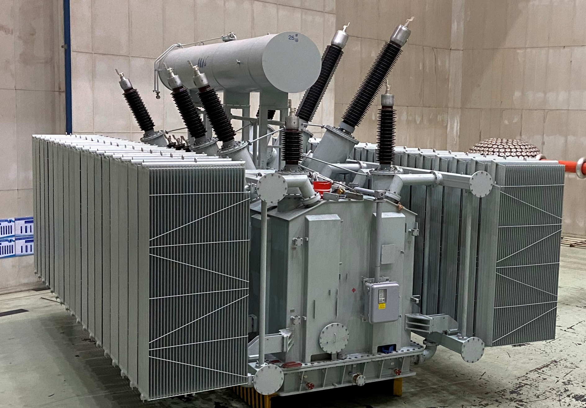
Power transformer winding quality is one of the most important factors buyers should evaluate before purchasing a transformer because winding performance directly affects efficiency, reliability, fault resistance, thermal stability, and service life. A transformer may meet its basic voltage and capacity requirements but still experience premature failure if the winding design is weak, poorly manufactured, or unsuitable for the application. Buyers who understand winding structures, materials, manufacturing processes, testing methods, and reliability indicators can make better purchasing decisions and reduce long-term operational risks.
Buyers can evaluate the quality of power transformer winding designs by reviewing the winding structure, conductor materials, insulation system, short-circuit withstand capability, cooling design, manufacturing processes, factory test results, and compliance with international standards. A high-quality winding design should demonstrate low losses, strong mechanical stability, effective heat dissipation, reliable insulation performance, and proven ability to withstand operating and fault conditions.
A transformer’s rated power and voltage specifications are sufficient to determine winding quality without reviewing design details or test results.False
Winding quality depends on internal design factors such as conductor arrangement, insulation coordination, mechanical strength, cooling performance, and verified testing results.
Why should buyers evaluate transformer winding design quality?
The winding system is one of the most technically demanding parts of a power transformer. It must perform reliably under both normal and abnormal operating conditions.
A high-quality winding design affects:
- Electrical efficiency
- Energy losses
- Temperature rise
- Short-circuit strength
- Voltage regulation
- Insulation lifetime
- Maintenance requirements
Poor winding design may result in:
- Excessive copper losses
- Overheating
- Partial discharge
- Insulation breakdown
- Mechanical deformation during faults
| Winding Quality Factor | Impact on Transformer Performance |
|---|---|
| Conductor design | Determines electrical losses |
| Insulation structure | Determines dielectric reliability |
| Mechanical strength | Determines fault resistance |
| Cooling arrangement | Determines temperature control |
What key winding design features should buyers review?
Before purchasing a power transformer, buyers should request detailed technical information about the winding structure.
Important evaluation areas include:
- Winding type
- Conductor arrangement
- Insulation system
- Cooling channels
- Mechanical reinforcement
- Manufacturing technology
Common winding designs include:
- Layer windings
- Helical windings
- Disc windings
- Continuous disc windings
- Foil windings
Each design has different performance characteristics.
| Winding Type | Typical Application | Quality Evaluation Focus |
|---|---|---|
| Layer winding | Distribution transformers | Manufacturing accuracy |
| Helical winding | High-current transformers | Mechanical strength |
| Disc winding | High-voltage transformers | Insulation performance |
| Continuous disc winding | Large power transformers | Fault withstand capability |
| Foil winding | Low-voltage high-current units | Current distribution |
How can buyers evaluate the winding structure and configuration?
The winding structure should match the transformer’s operating requirements.
Buyers should evaluate:
- Voltage level
- Current capacity
- Power rating
- Fault level
- Loading characteristics
For example:
A transmission transformer requires excellent insulation coordination and short-circuit strength, while an industrial transformer may require stronger overload capability.
A suitable winding design should provide:
- Balanced electrical stress
- Effective cooling paths
- Strong mechanical support
| Application | Important Winding Requirement |
|---|---|
| Utility transmission | High dielectric and mechanical strength |
| Industrial facilities | Strong overload capability |
| Renewable energy systems | Dynamic load performance |
| Data centers | Maximum reliability |
How should buyers evaluate transformer winding materials?
The conductor material directly affects transformer losses and durability.
Common conductor materials include:
- Copper
- Aluminum
Copper is widely used because it provides:
- High conductivity
- Strong mechanical properties
- Good thermal performance
Aluminum provides:
- Lower weight
- Lower material cost
- Acceptable electrical performance when properly designed
Buyers should evaluate:
| Material Factor | Importance |
|---|---|
| Conductivity | Determines energy losses |
| Mechanical strength | Determines fault resistance |
| Thermal properties | Determines cooling requirements |
| Material quality | Determines reliability |
Why is conductor arrangement important when evaluating winding quality?
A good conductor arrangement improves current distribution and reduces losses.
Poor arrangements can create:
- Uneven current flow
- Eddy current losses
- Local overheating
High-quality designs may use:
- Continuously transposed conductors (CTC)
- Multi-strand conductors
- Optimized conductor positioning
| Conductor Technology | Benefit |
|---|---|
| CTC conductors | Reduce circulating losses |
| Multiple strands | Improve current sharing |
| Optimized layout | Reduce hot spots |
How can buyers evaluate winding insulation design?
The insulation system determines how well windings withstand electrical stress.
Buyers should review:
- Turn insulation
- Layer insulation
- Main insulation
- Pressboard structures
- Oil insulation system
A strong insulation design should provide:
- High dielectric strength
- Good thermal stability
- Resistance to aging
| Insulation Component | Function |
|---|---|
| Turn insulation | Prevent turn faults |
| Layer insulation | Separate winding sections |
| Pressboard barriers | Control electrical stress |
| Oil insulation | Provide cooling and dielectric protection |
Why is short-circuit withstand capability an important winding quality indicator?
Short-circuit performance is one of the strongest indicators of winding mechanical quality.
During a short circuit, electromagnetic forces can cause:
- Radial deformation
- Axial movement
- Conductor displacement
A high-quality winding design includes:
- Strong clamping systems
- Reinforced support structures
- Optimized winding geometry
Buyers should request:
- Short-circuit withstand test information
- Design calculation reports
- Mechanical analysis results
| Evaluation Item | Why It Matters |
|---|---|
| Short-circuit rating | Shows fault capability |
| Clamping design | Prevents movement |
| Mechanical calculations | Verify structural strength |
How can buyers evaluate winding cooling performance?
Cooling performance directly affects transformer lifespan.
Poor winding cooling may cause:
- Hot spots
- Higher losses
- Faster insulation aging
Buyers should review:
- Cooling duct design
- Oil flow arrangement
- Temperature rise test results
Important cooling methods include:
- Natural oil circulation
- Forced oil circulation
- Directed oil flow
| Cooling Feature | Evaluation Purpose |
|---|---|
| Oil channels | Check heat removal |
| Duct arrangement | Verify circulation |
| Temperature rise data | Confirm thermal performance |
How do temperature rise test results indicate winding quality?
The temperature rise test verifies whether the winding design can safely handle rated load.
The test evaluates:
- Winding temperature rise
- Oil temperature rise
- Hot spot performance
A good result indicates:
- Effective cooling
- Proper conductor selection
- Controlled losses
| Test Result | Meaning |
|---|---|
| Low temperature rise | Efficient thermal design |
| Excessive rise | Possible design issues |
| Uneven heating | Poor cooling distribution |
What factory tests should buyers request for winding evaluation?
Factory tests provide objective evidence of winding quality.
Important tests include:
| Test | Purpose |
|---|---|
| Winding resistance test | Verify conductor integrity |
| Load loss test | Measure copper losses |
| Impedance test | Confirm winding characteristics |
| Temperature rise test | Verify cooling performance |
| Partial discharge test | Detect insulation defects |
| Frequency response analysis (FRA) | Detect winding deformation |
| Lightning impulse test | Verify insulation strength |
How does frequency response analysis help evaluate winding quality?
Frequency response analysis (FRA) is a valuable diagnostic method for assessing winding mechanical condition.
It can detect:
- Winding displacement
- Mechanical deformation
- Damage after transportation
- Fault-related movement
Buyers should consider FRA capability especially for:
- Large utility transformers
- High-voltage transformers
- Critical infrastructure applications
| FRA Application | Benefit |
|---|---|
| Factory baseline test | Creates reference data |
| Post-transport test | Detects movement |
| Fault investigation | Identifies deformation |
How should buyers evaluate the manufacturer’s winding manufacturing capability?
The manufacturer’s production capability strongly influences winding quality.
Buyers should review:
- Manufacturing experience
- Production equipment
- Quality control procedures
- Skilled engineering team
Important manufacturing processes include:
- Precision winding
- Vacuum drying
- Controlled insulation assembly
- Accurate clamping
| Manufacturing Capability | Quality Impact |
|---|---|
| Automated winding equipment | Better consistency |
| Clean assembly environment | Better insulation reliability |
| Process control | Reduced defects |
How do international standards support winding quality evaluation?
Power transformer winding design and testing commonly follow standards from:
- International Electrotechnical Commission
- Institute of Electrical and Electronics Engineers
These standards help define requirements for:
- Transformer performance
- Insulation coordination
- Temperature rise
- Short-circuit withstand capability
- Factory acceptance testing
Compliance with recognized standards provides buyers with confidence that winding designs have been evaluated according to accepted engineering practices.
What questions should buyers ask transformer manufacturers?
Before purchasing a power transformer, buyers should request clear technical answers.
| Buyer Question | Evaluation Purpose |
|---|---|
| What winding type is used? | Confirm application suitability |
| What conductor technology is applied? | Evaluate efficiency |
| How is short-circuit strength achieved? | Assess mechanical reliability |
| What insulation materials are used? | Evaluate lifespan |
| What cooling method is applied? | Assess thermal performance |
| What tests verify winding quality? | Confirm reliability |
How can buyers compare winding designs from different suppliers?
A reliable comparison should consider technical performance rather than only purchase price.
Recommended comparison factors:
| Evaluation Category | Supplier A | Supplier B |
|---|---|---|
| Winding structure | Compare | Compare |
| Loss performance | Compare | Compare |
| Temperature rise | Compare | Compare |
| Short-circuit capability | Compare | Compare |
| Factory testing | Compare | Compare |
The lowest initial price may not represent the lowest lifecycle cost if the transformer has higher losses or lower reliability.
How does winding quality affect transformer lifecycle value?
A high-quality winding design provides long-term benefits:
- Lower operating losses
- Reduced maintenance requirements
- Fewer unexpected failures
- Longer service life
- Better system reliability
For transformers operating for several decades, winding quality has a major impact on total ownership cost.
| Winding Improvement | Long-Term Benefit |
|---|---|
| Lower losses | Reduced energy costs |
| Better cooling | Longer insulation life |
| Stronger structure | Higher fault resistance |
| Better insulation | Reduced failure risk |
Conclusion
Winding design plays a fundamental role in determining the efficiency, reliability, and durability of power transformers. A well-engineered winding system reduces energy losses, improves heat dissipation, strengthens resistance against short-circuit forces, and protects insulation from premature aging. Factors such as winding configuration, conductor materials, insulation methods, and mechanical construction all contribute to transformer performance. By evaluating winding design quality alongside manufacturing standards, testing procedures, and supplier expertise, buyers can select transformers that provide stable operation, lower lifecycle costs, and reliable power delivery for decades.
FAQ
Q1: How do winding designs affect the performance of power transformers?
Transformer winding design has a major impact on electrical performance, mechanical strength, efficiency, thermal behavior, and service life. The windings are responsible for transferring electrical energy through electromagnetic induction, making their design one of the most important aspects of transformer engineering.
A properly designed winding improves:
Energy efficiency
Voltage regulation
Short-circuit withstand capability
Heat dissipation
Insulation reliability
Mechanical durability
Operational lifespan
The winding structure determines how effectively the transformer handles normal operating conditions as well as abnormal events such as overloads and short circuits.
Key winding design factors include:
Conductor material and arrangement
Number of turns
Winding type
Insulation system
Mechanical support
Cooling channels
Current density selection
Advanced winding designs use computer modeling and simulation tools to optimize electromagnetic fields, reduce losses, and improve reliability.
Q2: What are the main types of transformer winding designs?
Different applications require different winding structures. Common transformer winding types include:
Layer Windings
Layer windings are commonly used in smaller transformers and high-voltage windings. Conductors are arranged in layers to achieve compact construction and good insulation performance.
Helical Windings
Helical windings are often used for high-current, low-voltage applications. Their design provides excellent mechanical strength and current distribution.
Disc Windings
Disc windings are widely used in large power transformers. They provide:
High voltage withstand capability
Improved impulse distribution
Better cooling performance
Strong mechanical resistance
Foil Windings
Foil windings are typically used in low-voltage applications where uniform current distribution and reduced leakage fields are required.
The selection of winding type depends on transformer rating, voltage level, current requirements, and operating environment.
Q3: How does winding design influence transformer efficiency?
Winding design directly affects transformer losses and overall efficiency.
Major winding-related losses include:
Copper Losses
Copper losses occur because electrical resistance in the winding conductors converts energy into heat.
Factors affecting copper losses include:
Conductor size
Material selection
Current density
Winding arrangement
Operating temperature
Stray Load Losses
Improper winding design can increase leakage flux, creating additional losses in:
Windings
Clamping structures
Transformer tank components
Optimized winding designs reduce these losses by controlling magnetic flux distribution and improving conductor arrangement.
Q4: How do windings affect transformer short-circuit strength?
Mechanical strength is a critical requirement for transformer windings because short circuits create extremely high electromagnetic forces.
During a fault condition, windings experience:
Radial forces pushing conductors outward or inward
Axial forces compressing or stretching winding structures
A strong winding design includes:
Reinforced winding supports
Proper conductor bracing
High-strength insulation materials
Controlled winding compression
Accurate manufacturing tolerances
These features prevent:
Winding deformation
Insulation damage
Turn-to-turn failures
Permanent transformer damage
Transformers designed according to standards such as IEC 60076-5 and IEEE C57 requirements are tested for short-circuit withstand capability.
Q5: How does winding design influence transformer cooling?
Effective cooling is essential because winding losses generate significant heat during operation.
Winding designs improve cooling through:
Vertical oil ducts
Horizontal cooling channels
Optimized conductor spacing
Controlled oil circulation paths
Improved heat transfer surfaces
In oil-immersed transformers, oil flows through winding channels to remove heat.
In dry-type transformers, winding construction must allow sufficient airflow to prevent excessive temperature rise.
Poor winding cooling design can cause:
Hot spots
Faster insulation aging
Reduced load capability
Shortened service life
Q6: How do winding designs affect voltage regulation?
Voltage regulation describes how much the output voltage changes when transformer load changes.
Winding design affects voltage regulation through:
Leakage reactance
Winding arrangement
Coupling between primary and secondary windings
Physical distance between windings
Better coupling reduces leakage flux and improves voltage stability.
Engineers optimize winding placement to achieve the required balance between:
Low leakage reactance
Short-circuit strength
Insulation requirements
Q7: Why are winding insulation systems important?
The winding insulation system protects conductors from electrical breakdown and determines transformer reliability.
Important insulation components include:
Paper insulation
Pressboard barriers
Epoxy insulation
Resin systems
Oil insulation
A high-quality insulation design helps withstand:
Operating voltage stress
Lightning impulses
Switching surges
Thermal aging
Mechanical movement
Moisture control and proper manufacturing processes are essential because insulation deterioration is one of the leading causes of transformer failure.
Q8: What should buyers evaluate regarding transformer winding design?
When purchasing power transformers, buyers should evaluate winding-related specifications and manufacturing quality.
Important considerations include:
Winding type and configuration
Conductor material (copper or aluminum)
Short-circuit withstand capability
Insulation design
Temperature rise limits
Loss calculations
Cooling arrangement
Factory test results
Compliance with IEC 60076 or IEEE C57 standards
Manufacturer experience
A well-designed winding system improves transformer efficiency, reduces failure risks, and ensures reliable operation throughout the transformer's expected service life.
References
IEC 60076 – Power Transformers
https://webstore.iec.ch/publication/602
IEC 60076-5 – Power Transformers: Ability to Withstand Short Circuit
https://webstore.iec.ch
IEEE C57 Series – Power Transformer Standards
https://standards.ieee.org
Electrical Engineering Portal – Transformer Winding Design Principles
https://electrical-engineering-portal.com
IEEE Power & Energy Society – Transformer Performance and Design Research
https://ieeexplore.ieee.org