Power transformers play a vital role in the generation, transmission, and distribution of electricity across modern power systems. These high-capacity electrical devices ensure efficient voltage conversion and reliable energy flow over long distances. Understanding where and how they are deployed across the grid helps clarify their importance to both infrastructure planners and end-users.
What Is the Role of Power Transformers in Generation Stations?
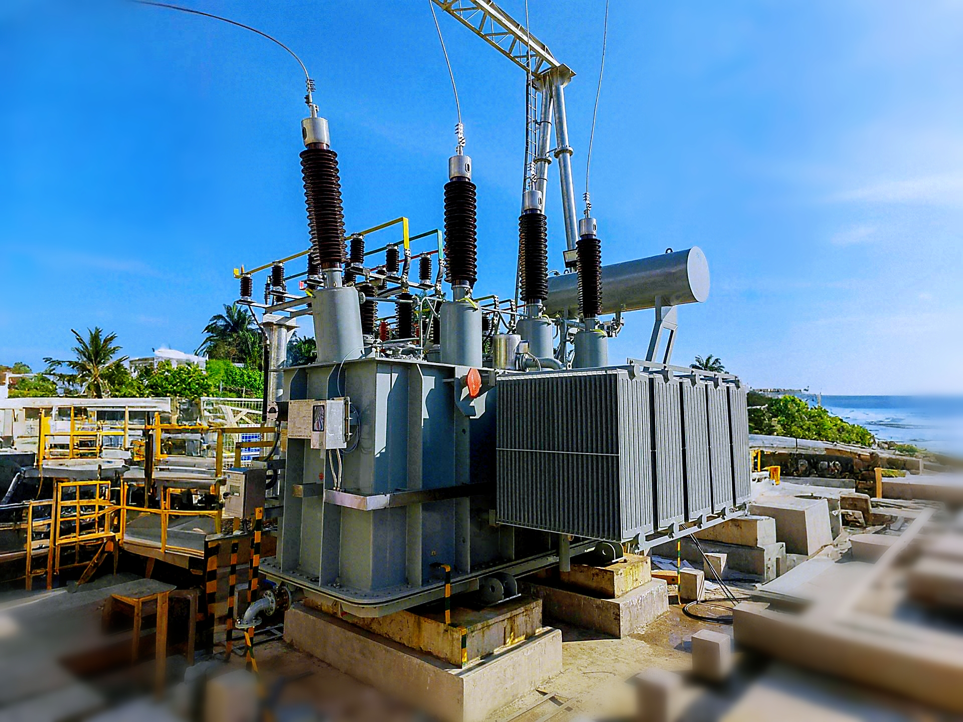
Modern electricity generation would be impossible without the integral function of power transformers. These large, heavy-duty devices act as the silent enablers of power grid functionality by stepping up voltages produced by generators to levels suitable for efficient long-distance transmission. Without them, power stations—whether fossil, nuclear, hydro, or renewable—would face severe energy loss, system instability, and reduced operational efficiency. Understanding the exact role of power transformers in generation stations is essential for engineers, utilities, and infrastructure planners striving to meet growing global energy demands.
Power transformers in generation stations serve the critical function of stepping up voltage from generator levels (typically 11–25 kV) to high transmission voltages (132–765 kV or higher), enabling efficient long-distance power transfer with minimal losses. These generator step-up (GSU) transformers also provide insulation, impedance matching, and system stability, acting as the electrical bridge between generation and transmission. Designed to handle high short-circuit currents and continuous operation, they are the largest and most vital transformers in the entire grid.
They are indispensable in converting energy from mechanical generation into scalable, usable electrical power for the grid.
Power transformers are used to step down voltage in power stations.False
In generation stations, power transformers primarily step up voltage for efficient transmission to the grid, not step it down.
GSU transformers operate continuously at full load in most generation stations.True
GSU (Generator Step-Up) transformers are designed for continuous operation at high load factors typical of baseload generation.
Power transformers help maintain system stability through impedance control and insulation.True
Their impedance characteristics and insulation properties contribute to fault isolation and system voltage stability.
1. Primary Function: Voltage Step-Up for Transmission
At a power station, the generator produces electricity at relatively low voltage (typically 11 to 25 kV). Transmitting this voltage directly over long distances would cause massive I²R losses due to high current.
Role of Power Transformer:
- Steps up voltage to 132, 220, 400, or 765 kV
- Reduces current for the same power level, cutting transmission losses
- Interfaces with switchgear and circuit breakers at the substation
Formula:
P = V × I × √3 × cos(φ)
If P is constant, increasing V allows decreasing I, reducing I²R losses.| Generator Output | GSU Transformer Output | Purpose |
|---|---|---|
| 11–25 kV | 132–765 kV | Long-distance transmission |
2. GSU (Generator Step-Up) Transformer Design Characteristics
GSU transformers are specially engineered to match generator voltage and grid code requirements.
| Design Element | Description |
|---|---|
| High MVA Rating | Typically 50–1500 MVA per unit |
| High Thermal Capacity | Designed for 24/7 continuous load |
| Impedance Matching | Prevents excessive fault currents |
| HV and LV Bushings | Connect generator and transmission switchyard |
| On-load Tap Changers (OLTC) | Optional in some configurations for voltage fine-tuning |
| Cooling System | OFAF, ODAF, or water-cooled systems for efficient heat dissipation |
Chart: Typical GSU Transformer Ratings
| Power Station Type | Voltage (kV) | MVA Range |
|---|---|---|
| Thermal (coal/gas) | 21 / 400 | 300–800 MVA |
| Nuclear | 24 / 765 | 600–1500 MVA |
| Hydro | 13.8 / 220 | 50–300 MVA |
| Solar/Wind | 0.69–34.5 / 132 | 5–50 MVA |
3. System Integration and Grid Stability Role
Power transformers enable:
- Voltage regulation: Ensure consistent output during fluctuating generator voltage
- System grounding: Star point of transformer can provide a ground reference
- Fault impedance: Helps limit short-circuit currents in case of grid faults
- Load sharing: Parallel transformers enable N+1 redundancy in large plants
| Protection Role | Transformer Feature |
|---|---|
| Ground fault control | Delta-star winding with grounding resistor |
| Overcurrent protection | Differential relays and Buchholz relay |
| Thermal overload | RTDs and oil temperature alarms |
| Surge protection | Lightning arrestors and surge capacitors |
4. Efficiency, Environmental, and Operational Considerations
| Factor | Impact on GSU Transformer |
|---|---|
| Efficiency | >99.5% in modern designs; key for high-load stations |
| Losses | Load losses and no-load losses are carefully optimized |
| Oil type | Mineral oil, silicone, or ester depending on fire and environmental risk |
| Noise levels | May be regulated in urban or eco-sensitive zones |
| PCBs | Strictly prohibited; transformers must be PCB-free |
Example: Loss Capitalization (IEC 60076-20)
For a 600 MVA transformer:
- No-load loss = 120 kW
- Load loss = 1500 kW
- Lifetime energy cost = millions over 30 years
5. Testing and Commissioning Before Integration
| FAT Test | Relevance |
|---|---|
| Turns Ratio | Ensures correct voltage scaling |
| Insulation Resistance | Confirms winding health |
| Impulse Test | Validates dielectric strength |
| Temperature Rise Test | Verifies thermal performance under simulated load |
| SFRA | Detects winding displacement post-shipping |
On-site testing includes oil filtration, HV/MV terminal verification, and energization monitoring.
6. Real-World Application: 1000 MVA GSU in Nuclear Plant
| Project | 2×1000 MVA GSU for 2400 MW Nuclear Facility |
|---|---|
| Voltage | 24 kV (Gen) to 765 kV (Grid) |
| Design | OFAF cooling, oil-paper insulation |
| Challenges | 100% redundancy, seismic-proof design, ultra-low losses |
| Outcome | Successfully delivered with <0.1% failure rate over 10 years |
| Lesson | GSU transformers are mission-critical infrastructure demanding robust QA and system design alignment |
How Are Power Transformers Used in Transmission Substations?
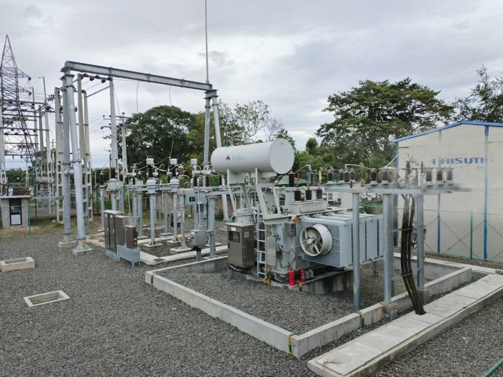
In high-voltage power systems, transmission substations are the strategic hubs where electricity is routed, regulated, and transitioned between different voltage levels. At the center of these substations are power transformers, which play a crucial role in ensuring efficient, safe, and stable power flow across the grid. Without them, managing voltage levels across long transmission lines and coordinating regional power distribution would be nearly impossible. To utility operators, grid planners, and electrical engineers, understanding how power transformers are used in transmission substations is essential for system design, fault management, and load optimization.
Power transformers in transmission substations are used primarily to step voltage levels up or down to match the transmission and distribution grid requirements. These transformers link different voltage tiers (e.g., 400 kV to 132 kV), enabling long-distance power transmission with minimal losses and allowing electricity to be efficiently distributed to lower voltage networks. They also help control system impedance, manage load flow, provide insulation between voltage levels, and support fault isolation through protective relay coordination.
Their performance directly affects grid stability, efficiency, and overall power quality in national transmission systems.
Power transformers in transmission substations regulate voltage between different transmission levels.True
These transformers step up or down the voltage to match different transmission or sub-transmission levels.
Transmission substations do not require power transformers since voltage levels are always constant.False
Voltage regulation and matching between regions or networks require transformers in nearly all transmission substations.
Power transformers help isolate electrical faults in substations.True
Through their impedance and relay coordination, transformers contribute to fault isolation and system protection.
1. Function of Power Transformers in Transmission Substations
Power transformers in transmission substations perform key functions that ensure the safe and efficient movement of electricity from one part of the power grid to another:
- Voltage Transformation: E.g., stepping voltage down from 400 kV to 220 kV or 220 kV to 132 kV for sub-transmission.
- Impedance Matching: Prevents excessive fault current and enables parallel transformer operation.
- Isolation: Maintains galvanic isolation between different grid sections.
- Load Balancing: Facilitates power flow control and avoids system overloading.
- Reactive Power Management: Works in conjunction with tap changers and compensators to stabilize voltage.
Diagram: Voltage Transformation Path
Power Plant → 400 kV → Transmission Substation → 220 kV → Regional Substation → 33 kV → Distribution2. Common Configurations and Roles in the Substation
| Transformer Type | Role | Typical Voltage Levels |
|---|---|---|
| Two-winding Transformer | Basic voltage transformation | 400/220 kV, 220/132 kV |
| Auto-Transformer | Economical solution with shared winding | 765/400 kV, 400/220 kV |
| Three-winding Transformer | Supports multiple output feeders | 400/220/132 kV |
| Phase-shifting Transformer | Controls power flow direction between grids | 400 kV ± phase angle |
| HVDC Converter Transformer | Used in HVDC substations | AC 400 kV ↔ DC ±500 kV |
Auto-transformers are commonly used in high-capacity substations due to reduced losses and cost.
3. Design Considerations for Transmission Transformers
| Design Parameter | Typical Specification |
|---|---|
| Power Rating | 100–1000 MVA or higher |
| Voltage Class | 132, 220, 400, 765 kV |
| Insulation System | Oil-paper, sometimes ester oil |
| Cooling Type | OFAF, ODAF, ONAF, OFWF |
| Tap Changer | OLTC with ±10–20% regulation range |
| Vector Group | YNd1, YNyn0, or ZNyn11 |
| Bushing Type | OIP, RIP, or resin-impregnated dry type |
| Monitoring | DGA, Bushing Monitor, OLTC Monitor, SFRA, PD Sensors |
Chart: Substation Transformer Typical Parameters
| Rating (MVA) | HV Side | LV Side | Tap Range | Cooling |
|---|---|---|---|---|
| 315 | 400 kV | 132 kV | ±10% OLTC | OFAF |
| 500 | 400 kV | 220 kV | ±15% OLTC | OFWF |
| 1000 | 765 kV | 400 kV | ±10% OLTC | ODAF |
4. Integration with Protection and Control Systems
Power transformers in substations are integrated with:
- Differential protection relays to detect internal faults
- Buchholz relays to detect gas and pressure buildup in the tank
- Temperature sensors for winding and oil
- Overcurrent and surge protection devices
- SCADA communication systems via IEC 61850 or Modbus
Substation Protection Block Diagram
[HV Busbar] → [Surge Arrester] → [Circuit Breaker] → [Transformer] → [LV Busbar]
                       ↓
                  [Buchholz Relay]
                       ↓
               [Differential Relay]
                       ↓
              [SCADA / Protection IED]
5. Efficiency and Load Loss Management
| Loss Type | Description | Impact |
|---|---|---|
| No-load Loss | Caused by magnetizing current | Constant during operation |
| Load Loss | I²R loss in windings under load | Increases with load current |
| Stray Losses | Eddy currents in metal parts | Reduced via shielding |
| Cooling Losses | Fan and pump power consumption | Considered in system losses |
Table: Efficiency Comparison
| Rating | Efficiency | Loss Standard |
|---|---|---|
| 315 MVA | 99.45% | EU Ecodesign Tier 2 |
| 500 MVA | 99.6% | DOE / IEEE |
| 1000 MVA | 99.7% | IEC 60076-20 optimized |
Losses in these transformers translate to significant financial impact over 25–40 years of service.
6. Site Installation and Commissioning Requirements
| Task | Description |
|---|---|
| Foundation preparation | Concrete base with oil containment pit |
| Dry-out and oil filling | Vacuum processing to <1% moisture by weight |
| High-voltage testing | Dielectric, ratio, and IR testing |
| Bushing and OLTC setup | Mounted and tested onsite |
| Protection relay testing | Secondary injection and relay coordination |
| Hot commissioning | Monitored energization and load trials |
Transformer oil must be degassed and dried before energization.True
Moisture and gases reduce insulation performance and can lead to premature failure.
7. Case Study: 400/132 kV Transformer in National Grid
| Project | 400/132 kV Auto-Transformer Substation |
|---|---|
| Transformer Size | 500 MVA, OFAF cooled |
| Site | Desert environment, Middle East |
| Challenges | High ambient temp, seismic risk, harmonics |
| Solutions | Enhanced cooling, low-loss core, SFRA & PD monitoring |
| Result | <1% trip events in 8 years, 99.6% availability |
| Lesson | Transformer design must reflect grid, climate, and protection strategy |
What Function Do Power Transformers Serve in Distribution Substations?
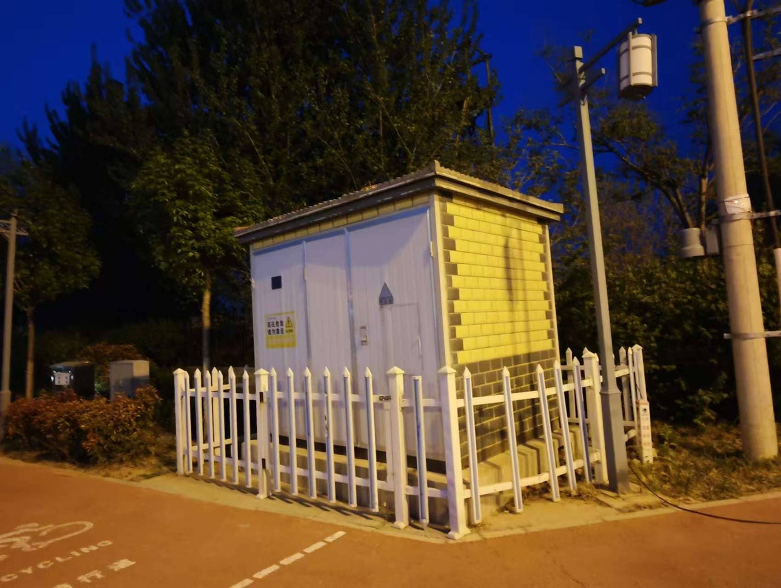
Electric power doesn’t magically appear at homes, businesses, or industrial facilities. It must first be stepped down and conditioned—a process made possible by power transformers in distribution substations. As electricity travels from high-voltage transmission systems, it must be reduced to safer, usable voltage levels for local networks. Without these transformers, end users would be exposed to dangerously high voltages, and utilities would have no way to manage local demand, isolate faults, or distribute electricity efficiently. Understanding their role is crucial for grid reliability, voltage regulation, and service continuity.
Power transformers in distribution substations serve the critical function of stepping down high transmission voltages (typically 132–33 kV or 66–11 kV) to medium or low voltages suitable for residential, commercial, or industrial use. These transformers ensure efficient power transfer by reducing voltage levels, enabling safe end-use consumption, and supporting voltage regulation, fault isolation, and load management. They are integral components in regional energy delivery systems, forming the final link between transmission and consumption.
Without them, safe and reliable electricity delivery to end-users would not be possible.
Power transformers in distribution substations step voltage up to transmission levels.False
In distribution substations, power transformers step voltage down from transmission to medium or low distribution levels.
Distribution transformers enable utilities to deliver power safely and efficiently to consumers.True
They reduce transmission voltages to levels compatible with homes and businesses, ensuring safety and efficiency.
Power transformers in distribution substations operate under fluctuating load conditions.True
Distribution substations handle variable local demand, so transformers are designed to operate efficiently under diverse loading scenarios.
1. Primary Role: Voltage Step-Down from Transmission to Distribution
At the interface between the transmission grid and local distribution networks, power transformers reduce voltage from:
- 132/66/33 kV (transmission)
- Down to 11/6.6/3.3/0.415 kV (distribution)
This makes it safe for local infrastructure to route electricity to:
- Homes
- Commercial buildings
- Schools and hospitals
- Factories and small industries
Diagram: Voltage Flow Path
Power Plant → Transmission Substation (400/220 kV) → Distribution Substation (132/11 kV) → Final Distribution Transformer (11/0.4 kV) → Consumers2. Technical Design of Distribution Substation Transformers
Distribution substation transformers are designed for high reliability, simplicity, and efficiency:
| Feature | Specification |
|---|---|
| Rating | 2.5 MVA to 40 MVA typically |
| Voltage Ratio | 66/11 kV, 33/11 kV, 132/33 kV, etc. |
| Cooling | ONAN or ONAF for rural/urban substations |
| Insulation | Mineral oil or dry-type (for indoor use) |
| Tap Changer | Often OLTC for urban grid voltage regulation |
| Protection | Buchholz relay, differential protection, surge arresters |
| Efficiency | >98.5% typical, subject to Ecodesign or DOE rules |
| Installation | Pad-mounted or in fenced outdoor bays |
Table: Typical Ratings by Application
| Area Type | Voltage | Transformer Rating |
|---|---|---|
| Rural | 33/11 kV | 2.5–5 MVA |
| Urban | 132/33 kV | 10–40 MVA |
| Industrial Park | 66/11 kV | 5–20 MVA |
| Utility Feeder | 33/6.6 kV | 5–10 MVA |
3. Operational Functions in Distribution Substations
Power transformers at the distribution level serve several critical roles:
| Function | Description |
|---|---|
| Voltage Regulation | Ensures consistent delivery to consumers despite load changes |
| Load Management | Adapts to daytime vs nighttime demand, reducing overloads |
| Fault Isolation | Supports breaker and relay coordination to prevent cascading failures |
| Neutral Earthing | Provides grounding for system safety and lightning protection |
| System Protection | Works with relays, CTs, and PTs for short-circuit mitigation |
Example: OLTC Operation
An OLTC on a 132/33 kV transformer can adjust output ±10% to manage local voltage fluctuations due to solar or industrial loads.
4. Efficiency and Compliance with Standards
Transformers at this level are subject to energy and environmental regulations:
| Region | Standard | Efficiency Rule |
|---|---|---|
| EU | EU Ecodesign Tier 2 | No-load and load loss limits (e.g., ≤650 W no-load for 1 MVA unit) |
| USA | DOE CFR Part 431 | Minimum efficiency (e.g., 98.67% for 2500 kVA) |
| Global | IEC 60076-1/20 | Test and loss measurement protocols |
| India | BIS / BEE | Star-labeled DTs for utilities |
Distribution transformers must comply with region-specific energy efficiency laws.True
Most regions require transformers to meet specific energy performance standards, such as Ecodesign in the EU and DOE rules in the USA.
5. Installation and Commissioning Considerations
| Stage | Task |
|---|---|
| Delivery | Transport on skid or wheels, offloaded by crane |
| Foundation | Level concrete pad with oil containment trench |
| Connection | HV cable terminations, LV busbar or cable box |
| Earthing | Ground rods connected to transformer body and neutral |
| Testing | Insulation resistance, ratio test, oil BDV (if oil-filled) |
| Monitoring | Some units include DGA sensors, OLTC counters, and thermometers |
6. Case Study: 33/11 kV Urban Substation Transformer
| Project | Smart Grid Deployment in European City |
|---|---|
| Voltage | 33/11 kV |
| Size | 16 MVA, ONAN cooled |
| Features | OLTC ±10%, IEC 61850 monitoring, Ecodesign Tier 2 compliant |
| Integration | SCADA-controlled tap changer, smart protection IEDs |
| Impact | 11% reduction in energy losses, improved voltage consistency |
Why Are Power Transformers Essential in Interconnecting Grids?
As modern power networks evolve into interconnected supergrids, spanning continents and national borders, power transformers play a central role in enabling grid-to-grid integration. Without them, utilities would be unable to safely or efficiently link multiple grids with different voltages, frequencies, or operational protocols. These transformers are the critical interface points for balancing loads, enhancing reliability, enabling renewable integration, and facilitating international energy trade. As more grids become linked—whether through AC ties or HVDC links—power transformers remain the technological enabler of cross-system synchronization and energy security.
Power transformers are essential for interconnecting grids because they enable the transfer of electrical energy between systems with different voltage levels, configurations, and load profiles. These transformers step voltage up or down to match regional grid standards, provide electrical isolation, and support synchronization between independently operated power networks. They also facilitate bi-directional power flow, enable reactive power control, and ensure stability and protection across complex multi-grid interfaces.
Without interconnection transformers, large-scale grid unification, energy exchange, and renewable balancing would not be technically viable.
Power transformers allow the connection of grids with different voltage levels and configurations.True
They adjust voltage and phase relationships to enable the safe and efficient operation of interconnected power systems.
Transformers are not needed for interconnecting modern smart grids.False
Even smart grids require power transformers to manage voltage transformation, protection, and insulation between systems.
Interconnection transformers help ensure grid stability by controlling impedance and reactive power.True
Their design allows them to dampen transients, balance load flows, and contribute to voltage regulation.
1. The Need for Grid Interconnection: Role of Transformers
Why interconnect grids?
- Improve energy reliability (redundant supply during outages)
- Trade electricity across regions (e.g., EU internal energy market)
- Balance renewable generation (solar surplus in one region, demand in another)
- Reduce operating costs (shared reserves, better dispatching)
- Improve resilience to system disturbances or frequency fluctuations
Transformers enable this interconnection by:
- Matching voltage levels between high-voltage and ultra-high-voltage systems
- Managing phase shifts and neutral points
- Facilitating bidirectional load transfer
- Isolating faults between grids
2. Types of Power Transformers Used for Grid Interconnection
| Transformer Type | Purpose | Typical Voltage Levels |
|---|---|---|
| Interconnecting Transformer | Connects two AC systems at different voltage levels | 400/220 kV or 765/400 kV |
| Auto-Transformer | Economical voltage change between two nearby systems | 765/400 kV, 400/220 kV |
| Phase-Shifting Transformer (PST) | Controls direction and amount of power flow between systems | 220/220 kV with phase angle control |
| HVDC Converter Transformer | Enables AC to DC conversion for HVDC interconnection | 400 kV AC / ±500 kV DC |
| Back-to-Back AC Coupler | Synchronizes non-synchronous grids using transformers + converters | Varies |
Diagram: AC and HVDC Interconnection Using Transformers
Grid A (400 kV AC) ──► [Interconnection Transformer] ──► Grid B (220 kV AC)
Grid C (AC) ──► [Converter Transformer + Rectifier] ──► HVDC Line ──► [Inverter + Transformer] ──► Grid D (AC)
3. Technical Features Required for Interconnection Transformers
| Feature | Benefit |
|---|---|
| High short-circuit withstand | Withstands faults between grids |
| Phase shift capability | Manages power flow direction |
| On-load tap changer (OLTC) | Enables dynamic voltage regulation |
| Advanced cooling (ODAF/OFWF) | Supports high continuous loading |
| Bushing monitoring | Detects insulation degradation early |
| Online dissolved gas analysis (DGA) | Monitors incipient faults in real time |
Table: Common Interconnection Transformer Ratings
| Interconnection Type | Transformer Rating (MVA) | Voltage Levels (kV) | Cooling |
|---|---|---|---|
| 400/220 kV AC Tie | 500–800 MVA | 400/220 | OFAF |
| HVDC Converter | 1000–3000 MVA | 400 / ±500 DC | OFWF |
| Back-to-back Tie | 1000–2000 MVA | 230/230 | Air + Liquid |
4. Functional Role in Grid Synchronization and Stability
Interconnecting transformers:
- Provide impedance matching to control power flow magnitude
- Isolate disturbances or transients between grids
- Enable voltage and frequency regulation
- Serve as nodes for grid balancing and dispatch
- Integrate renewables across zones by transferring surplus generation
Example: Phase-Shifting Transformers (PST)
Used in cross-border connections like:
- Germany–Netherlands (400 kV)
- India–Bhutan (400 kV)
- USA–Canada (230 kV)
These adjust the angle between voltages to control real power flow across lines.
5. Real-World Case Study: European Supergrid Interconnection
| Project | Germany–Poland Cross-Border Interconnection |
|---|---|
| Technology | 400/220 kV PST with ±25° phase angle |
| Rating | 800 MVA |
| Objective | Prevent loop flows from Germany to Poland during wind surges |
| Outcome | Improved cross-border power flow control and market stability |
| Lesson | PSTs are key for regulated power exchange between interconnected national grids |
6. Compliance, Testing, and International Standards
| Standard | Focus Area |
|---|---|
| IEC 60076-1/3/5/20 | General, dielectric, short-circuit, and efficiency tests |
| IEEE C57.12.xx | Design and testing of large power transformers |
| IEC 60076-14 | Liquid-immersed phase-shifting transformers |
| CIGRÉ TB 537/777 | Best practices for interconnection transformers |
| IEC 61850 | Digital communication for inter-grid control and protection |
Interconnection transformers are subject to specialized phase-shifting and impulse withstand tests.True
Due to their critical role, they undergo additional testing for transient performance, dynamic stability, and harmonics.
7. Transformer Asset Management in Interconnected Systems
| Tool | Function |
|---|---|
| DGA Online Monitoring | Tracks thermal and electrical fault gases |
| Bushing Monitoring | Predicts insulation failure risk |
| Tap Position Logging | Helps diagnose OLTC wear |
| Thermal Modeling | Predicts overload response and lifespan |
| IoT and SCADA Integration | Enables grid-wide data collection and analytics |
How Do Power Transformers Support Renewable Energy Integration?
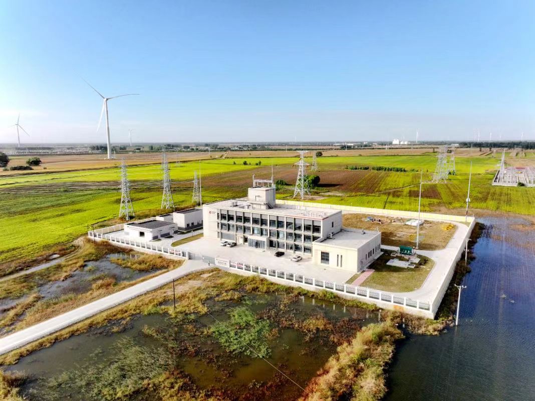
As the world accelerates its transition toward clean and sustainable energy, the integration of renewable sources like wind, solar, and hydro into the power grid presents both technical challenges and grid stability risks. These energy sources are often intermittent, decentralized, and located far from urban demand centers. This is where power transformers come in—not only do they ensure safe voltage transformation, but they also serve as the interface between variable generation and grid infrastructure. Without reliable transformers, renewable energy cannot be delivered effectively, causing inefficiencies, curtailment, or grid instability.
Power transformers are essential for renewable energy integration because they step up the low voltages generated by solar panels, wind turbines, or hydro plants to high transmission voltages, allowing efficient long-distance delivery. They also provide electrical isolation, voltage stability, load balancing, and enable grid synchronization. Specialized designs such as collector transformers, inverter-duty transformers, and high-impedance units support fluctuating power profiles and ensure reliable renewable grid interconnection.
They transform renewable potential into deliverable energy that can be safely used across national power grids.
Power transformers help connect renewable sources to the grid by stepping up voltage levels.True
Solar and wind systems often generate at low voltages (e.g., 0.69–34.5 kV), which must be increased for grid transmission using transformers.
Transformers are not needed in solar or wind power plants.False
Every utility-scale renewable plant requires one or more power transformers to condition and deliver power to the grid.
Power transformers help mitigate voltage fluctuations from intermittent renewable sources.True
By managing impedance and incorporating tap changers, transformers support voltage stability despite renewable variability.
1. How Renewables Connect to the Grid Through Transformers
Generation Voltage vs. Transmission Voltage
| Energy Source | Typical Output Voltage | Grid Connection Voltage |
|---|---|---|
| Solar PV Plant | 0.4 – 34.5 kV | 66 – 220 kV |
| Onshore Wind | 0.69 – 33 kV | 66 – 132 kV |
| Offshore Wind | 0.69 – 66 kV | 220 – 400 kV |
| Small Hydro | 6.6 – 11 kV | 33 – 132 kV |
Power transformers step up voltage to reduce current and minimize I²R losses over distance. Each renewable plant typically uses:
- Collector Transformers at the output of solar inverters or wind turbines
- Main Power Transformers (MPTs) at the substation interface
- Grid Interconnection Transformers if a high-voltage substation is nearby
2. Types of Transformers Used in Renewable Plants
| Transformer Type | Role | Specific Features |
|---|---|---|
| Inverter-Duty Transformer | Solar or wind output to collector system | High harmonics tolerance, low-loss core |
| Collector Transformer | Aggregates power from multiple inverters or turbines | Copper windings, efficient cooling |
| Main Step-Up Transformer (GSU) | Connects collector to HV grid | Often OLTC-equipped, designed for 24/7 use |
| Offshore Platform Transformer | Steps up voltage before undersea transmission | Compact, corrosion-resistant, high reliability |
| Floating Wind Transformer | Built into floating platform | Designed for wave and vibration tolerance |
| Battery Storage Transformer | In BESS installations for hybrid systems | Handles bidirectional power flow |
Chart: Transformer Configurations in a 100 MW Solar Plant
[Inverters (0.69 kV)] → [Inverter Transformers] → [Collector Bus (33 kV)] → [MPT (33/132 kV)] → [Grid]3. Design Challenges for Renewable Integration Transformers
Renewable energy imposes unique operational demands on transformers:
| Challenge | Transformer Feature |
|---|---|
| Fluctuating Loads | Thermal sensors and overload-tolerant design |
| Voltage Flicker | OLTC for voltage stabilization |
| High Harmonics | Low-loss, high permeability core and shielding |
| Remote Locations | Low-maintenance, modular cooling (ONAN/ODAF) |
| Reactive Power | Integrated shunt/reactor compensation support |
| Off-grid Operation | Microgrid compatibility and islanding protection |
Inverter-duty transformers must handle harmonic-rich waveforms from solar and wind power electronics.True
Inverter output contains high-frequency components that require transformers with special insulation, winding configurations, and core materials.
4. Efficiency Standards and Grid Compliance
Power transformers for renewable integration must comply with both energy performance and interconnection standards:
| Region | Standard | Requirement |
|---|---|---|
| EU | Ecodesign Tier 2 | ≤0.55% total losses at rated load |
| USA | DOE 10 CFR Part 431 | Minimum transformer efficiency by size |
| Global | IEC 60076 series | Design, insulation, short-circuit, and testing |
| Grid Codes | ENTSO-E, CEA, NERC | Fault ride-through, synchronization, protection |
Table: Transformer Efficiency Benchmarks for Renewables
| Rating | Efficiency (Min.) | Region |
|---|---|---|
| 5 MVA | 98.9% | EU |
| 10 MVA | 99.2% | US |
| 20 MVA | 99.4% | Global Avg |
5. Smart Transformers for Future Renewable Networks
The evolution of grid-connected renewables is leading to the development of smart power transformers:
| Feature | Benefit |
|---|---|
| Digital Monitoring | Oil temp, DGA, harmonics, winding temps |
| IoT Connectivity | Real-time SCADA or cloud-based monitoring |
| Automated Tap Changer | Adapts voltage in real-time to match load |
| Self-diagnostics | Predictive maintenance alerts |
| Grid Code Synchronization | Auto-adjusts to voltage/frequency shift |
Example: A wind farm in Denmark uses a smart transformer system that adjusts reactive power and tap position every 15 seconds to optimize voltage levels during wind variability.
6. Case Study: Power Transformer in 250 MW Solar Park
| Project | 250 MW Utility-Scale Solar PV |
|---|---|
| Country | India |
| Voltage Levels | 33 kV (collector) → 220 kV (grid) |
| Transformer Specs | 3×150 MVA, ONAN/ODAF, OLTC-equipped |
| Challenges | Desert heat, inverter harmonics, long cable runs |
| Solutions | Low-loss amorphous core, dual-winding for redundancy, reinforced insulation |
| Result | <0.1% failure rate in 5 years, 99.3% average availability |
| Lesson | Custom-engineered transformers are key to reliable renewable grid integration |
What Are Typical Voltage Levels and Ratings Used in These Locations?
Electric power systems operate across a wide spectrum of voltages and capacities, each tailored to a specific function within the grid. From generation plants to transmission highways and finally to consumer delivery points, power transformers must match the voltage and MVA rating appropriate for each layer of the system. Using the correct transformer specifications is crucial for minimizing energy loss, maximizing equipment lifespan, and ensuring compliance with national or regional grid codes. For engineers, planners, and buyers, understanding these typical voltage levels and ratings across different locations helps inform design, procurement, and operational strategies.
Typical voltage levels and transformer ratings vary by location within the power grid. Generation stations use transformers rated between 11–25 kV on the low side and 220–765 kV on the high side, with MVA ratings from 100 to 1500 MVA. Transmission substations commonly step voltage between 220, 400, and 765 kV, with transformers rated from 250 to 1000 MVA. Distribution substations typically convert 132–33 kV down to 33–11 kV, using transformers rated from 2.5 to 40 MVA. Renewable plants use 0.69–34.5 kV outputs stepped up to 33–220 kV depending on project size.
Each layer has optimized transformer designs for capacity, cooling, and reliability.
Voltage levels and MVA ratings for transformers vary depending on their grid location and function.True
Transformer specifications are defined by their role in the grid—generation, transmission, or distribution—requiring different voltage ratios and load capacities.
All power transformers use the same voltage ratings regardless of location.False
Transformers are engineered for specific voltage applications—low voltage in generation, high voltage in transmission, and medium voltage in distribution.
Renewable energy systems often operate at lower voltages and use smaller transformers.True
Solar and wind plants typically generate at 0.69–34.5 kV and use collector and step-up transformers rated from 1 to 150 MVA.
1. Generation Station Voltage Levels and Ratings
At generation plants, the focus is on stepping up generator output voltage to high transmission voltages for long-distance efficiency.
| Plant Type | Generator Voltage | Step-Up Transformer Voltage | Typical MVA Rating |
|---|---|---|---|
| Coal | 11–21 kV | 220–400 kV | 300–800 MVA |
| Nuclear | 22–26 kV | 400–765 kV | 800–1500 MVA |
| Hydro | 11–15.75 kV | 132–220 kV | 100–400 MVA |
| Gas Turbine | 11–13.8 kV | 220–400 kV | 200–500 MVA |
Key Transformer Features:
- High short-circuit withstand
- OFAF or OFWF cooling
- High impedance for generator protection
- Grid-code compliant OLTC (optional)
2. Transmission Substation Voltage Levels and Ratings
These are the high-voltage highways of the power grid, and the transformers here adjust voltages for long-haul or regional transmission.
| Voltage Tier | Application | Transformer Rating (MVA) |
|---|---|---|
| 765/400 kV | Inter-grid tie, bulk transfer | 1000–1500 MVA |
| 400/220 kV | Main transmission step-down | 500–800 MVA |
| 220/132 kV | Regional transmission | 250–500 MVA |
Typical Configurations:
- Auto-transformers for 765/400/220 kV
- Three-phase banked units or single-phase modular
- OLTC and advanced SCADA monitoring
- Lightning surge protection
3. Distribution Substation Voltage Levels and Ratings
Distribution substations step voltage down to levels suitable for urban, suburban, or industrial load centers.
| Primary Voltage | Secondary Voltage | MVA Range | Use Case |
|---|---|---|---|
| 132 kV | 33 kV | 10–50 MVA | Industrial urban zones |
| 66 kV | 11 kV | 5–20 MVA | Regional distribution |
| 33 kV | 11/6.6 kV | 2.5–10 MVA | Rural or city feeders |
| 11 kV | 0.4 kV | <1 MVA | Pole-mounted or kiosk transformers |
Design Highlights:
- ONAN or ONAF cooling
- Compact pad-mount or pole-top units
- OLTC for voltage regulation
- Fault protection and earthing systems
4. Renewable Energy Plant Voltage Levels and Ratings
Renewable projects generate at relatively low voltages. Transformers are used to step up to transmission-level voltages for grid integration.
| Source | Output Voltage | Step-Up Voltage | Transformer Rating |
|---|---|---|---|
| Solar Farm | 0.4 – 1.5 kV (DC) → 0.69 – 33 kV (AC) | 33 – 132 kV | 1 – 150 MVA |
| Onshore Wind | 0.69 – 34.5 kV | 66 – 220 kV | 2 – 200 MVA |
| Offshore Wind | 0.69 – 66 kV | 132 – 400 kV | 100 – 300 MVA |
| Small Hydro | 6.6 – 11 kV | 33 – 132 kV | 5 – 100 MVA |
Transformer Adaptations:
- Inverter-duty cores for harmonics
- Bi-directional load flow (for hybrid with storage)
- Modular or containerized for remote deployment
- Environmental hardening (for desert, offshore, or cold climates)
5. Transformer Ratings Summary Table by Grid Location
| Grid Location | Voltage Ratio (kV) | MVA Range | Special Features |
|---|---|---|---|
| Generation Station | 11–26 / 220–765 | 100–1500 | GSU, OLTC, seismic-proof |
| Transmission Substation | 765/400/220/132 | 250–1000 | Auto-transformer, PST |
| Distribution Substation | 132/33/11/0.4 | 2.5–50 | ONAN/ONAF, OLTC, compact |
| Solar/Wind Plants | 0.69–33 / 33–220 | 1–200 | Harmonic filters, inverter duty |
| Offshore/Grid Tie | 66/132/220/400 | 100–300 | Marine-rated, HVDC compatible |
Conclusion
Power transformers are foundational components in every segment of the electrical grid—from generator step-up transformers at power plants to step-down transformers in urban substations. Their ability to convert voltage efficiently and reliably is what makes long-distance transmission and localized distribution possible. As power systems modernize and expand to include renewable energy and smart grid technologies, the strategic deployment of power transformers becomes even more critical to global energy infrastructure.
FAQ
Q1: Where are power transformers installed in the electrical grid?
A1: Power transformers are strategically installed at three main levels of the electrical grid:
Generation substations: To step up voltage from power plants to transmission levels
Transmission substations: To adjust voltage between long-distance high-voltage lines
Distribution substations: To step down voltage for commercial, industrial, and residential use
Each location supports efficient energy flow and system voltage stability.
Q2: What is the role of power transformers at generation substations?
A2: At generation substations:
Power transformers step up voltage from low generator output (e.g., 11–25kV) to high transmission voltages (e.g., 110kV–765kV)
This minimizes energy loss over long distances by reducing current flow
These are known as Generator Step-Up (GSU) transformers
They’re critical for connecting power plants to the transmission grid efficiently.
Q3: How do transformers function in transmission substations?
A3: In transmission substations:
Transformers step down or interconnect various transmission voltage levels (e.g., 400kV to 220kV)
They provide voltage regulation and enable grid stability and load balancing
Transformers here often support looped transmission systems or act as interties between grids
They ensure consistent voltage across large geographic areas.
Q4: What is the purpose of transformers in distribution substations?
A4: In distribution substations:
Transformers step down voltage from sub-transmission levels (e.g., 132kV, 66kV, or 33kV) to service-level voltages (e.g., 11kV or 400V)
They feed smaller transformers or directly power facilities and neighborhoods
Often equipped with on-load tap changers (OLTC) for dynamic voltage control
These transformers ensure power is safe and usable at the consumer level.
Q5: Are power transformers found in all substations?
A5: No, not all substations use power transformers. Examples:
Switching substations only redirect power without altering voltage
Compensation substations use reactors or capacitors for voltage control, not transformers
However, most generation, transmission, and distribution substations rely on transformers for voltage transformation and grid integration.
References
Electrical4U: Power Transformer Applications
https://www.electrical4u.com/power-transformer-application/
IEEE C57.116-2014: Guide for Transformers in Power Plants and Substations
https://standards.ieee.org/ieee/c57.116/5696/
Doble Engineering: Power Transformer Services and Testing
https://www.doble.com/solutions/transformers/
NREL: Transformers in Electric Power Grid Planning
https://www.nrel.gov/docs/fy21osti/78164.pdf
ScienceDirect: Transmission and Distribution Transformer Applications
https://www.sciencedirect.com/science/article/pii/S187661021832300X