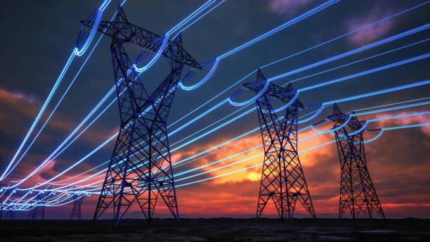
Power transformers are indispensable to modern electrical infrastructure because electricity must be transferred between different voltage levels before it can be generated, transmitted over long distances, distributed locally, and safely consumed. Without appropriately designed transformers, transmission losses would increase, equipment could be exposed to unsuitable voltages, and power networks would become more difficult and expensive to operate. For utilities, industrial facilities, and infrastructure developers, understanding the role of transformers across the power system is essential for selecting reliable equipment and designing efficient networks.
Power transformers are critical because they connect power generation, transmission, and distribution networks by efficiently changing voltage levels. Step-up transformers increase generator voltage for long-distance transmission, reducing current and minimizing transmission losses, while step-down transformers reduce voltage for distribution and end-use applications. Their capacity, voltage ratio, insulation, cooling, and protection systems must be matched to the requirements of each stage of the power system.
Transformers therefore function as essential links throughout the electrical network rather than as standalone pieces of equipment. Their design and performance directly influence power-system efficiency, reliability, safety, and operating costs.
Why Are Power Transformers Critical for Power Generation, Transmission, and Distribution?

Electricity must travel through several voltage levels before it reaches the final user, and generating electricity at one voltage while consuming it at another creates a fundamental engineering challenge. Without efficient voltage conversion, transmission current would be unnecessarily high, line losses would increase, and equipment across the power system would need to handle impractical voltage and current conditions. Power transformers are critical because they efficiently change AC voltage and current levels while transferring electrical power between generation, transmission, distribution, and utilization networks. Step-up transformers raise generator voltage to reduce transmission current and (I^2R) losses over long distances, while step-down transformers progressively reduce voltage to levels suitable for distribution networks and end users. Their impedance, insulation system, cooling design, voltage ratio, capacity, and protection systems therefore directly influence grid efficiency, reliability, safety, and power quality.
Power transformers are mainly used to generate electricity rather than transfer and change electrical voltage.False
Generators convert mechanical energy into electrical energy, while transformers transfer AC electrical power between circuits and change voltage and current levels through electromagnetic induction.
How Do Power Transformers Connect the Entire Power System?
A modern power system can be viewed as a sequence:
Generation → Step-up transformation → High-voltage transmission → Substation transformation → Distribution → End-use equipment
Power transformers provide the voltage transitions between these stages.
At the generating station, generators typically produce electricity at a voltage that is much lower than the voltage used for long-distance transmission. A step-up transformer increases the voltage before the electricity enters the transmission network.
At transmission substations, transformers may adjust voltage between different high-voltage network levels.
Closer to consumers, step-down transformers reduce voltage for medium-voltage distribution systems and eventually for utilization equipment.
This makes transformers fundamental to the architecture of the electrical grid rather than simply auxiliary equipment.
Why Is Voltage Stepped Up for Transmission?
For a three-phase system, apparent power is approximately:
[S=\sqrt{3}VI]
For a given power level, increasing voltage allows current to decrease.
This is extremely important because conductor losses are approximately:
[P_{loss}=I^2R]
If current is reduced by a factor of 2, the resistive loss theoretically falls by a factor of 4, assuming conductor resistance remains unchanged.
Therefore, increasing transmission voltage allows large amounts of electrical power to be transported with lower current and lower resistive losses.
The power relationship illustrated here provides the basic foundation for understanding why voltage and current must be managed carefully throughout a power network.
What Does a Step-Up Power Transformer Do?
A step-up transformer has a higher secondary voltage than its primary voltage.
Ideally:
[\frac{V_2}{V_1}\approx\frac{N_2}{N_1}]
where:
- (V_1) = primary voltage
- (V_2) = secondary voltage
- (N_1) = primary turns
- (N_2) = secondary turns
If the secondary has more turns than the primary, the transformer can increase voltage.
The corresponding current relationship moves in the opposite direction for approximately conserved apparent power.
In simplified form:
[V_1I_1\approx V_2I_2]
Thus, increasing voltage allows current to decrease for the same transmitted power.
This is the basic electrical reason transformers are so valuable for long-distance transmission.
Why Can't Generators Simply Produce Transmission Voltage Directly?
In principle, generators can be designed for different voltage levels, but generating and transmitting power involve different engineering requirements.
Generators must consider:
- Rotor and stator design
- Mechanical forces
- Insulation
- Generator cooling
- Excitation systems
- Mechanical speed
- Power output
- Grid connection
A transformer allows the generator and transmission network to be optimized more independently.
The generator can operate at a practical generation voltage, while a dedicated step-up transformer raises that voltage to the level appropriate for the transmission system.
This separation provides flexibility and simplifies system design.
Why Are Transformers Important at Transmission Substations?
Transmission networks often operate at multiple voltage levels.
A major substation may need to:
- Increase voltage
- Decrease voltage
- Interconnect transmission circuits
- Control voltage
- Isolate equipment
- Support protection and switching
- Accommodate changing power-flow conditions
Power transformers provide the electrical interface between these voltage levels.
For example, a transmission corridor may operate at one high-voltage level while another part of the grid uses a different voltage level. A transformer allows the two networks to exchange power while maintaining their required voltage characteristics.
Why Are Step-Down Transformers Necessary?
The very high voltages used for transmission are not generally appropriate for direct connection to ordinary distribution or utilization equipment.
Step-down transformers progressively reduce voltage.
The process can be represented as:
Transmission voltage → sub-transmission voltage → medium-voltage distribution → utilization voltage
The exact levels vary by country, utility, application, and network design.
At each stage, the transformer must be selected for the required:
- Voltage ratio
- MVA capacity
- Insulation level
- Impedance
- Cooling system
- Tap range
- Environmental conditions
- Protection requirements
How Do Distribution Transformers Support End Users?
Distribution transformers are typically installed closer to consumers.
Their role is to reduce distribution-system voltage to levels appropriate for buildings, industrial facilities, commercial sites, or other electrical loads.
These transformers may be exposed to very different operating conditions from large transmission transformers.
They can experience:
- Highly variable loads
- Daily load cycles
- Ambient temperature changes
- Outdoor exposure
- Humidity
- Pollution
- Lightning
- Harmonic-producing equipment
Therefore, transformer design must match the installation environment and load profile.
Why Is Transformer Efficiency So Important?
Transformers operate continuously in many power systems.
Even relatively small losses can accumulate into significant energy consumption over years of operation.
Two major categories are:
Core or no-load losses
These occur whenever the transformer is energized and include hysteresis and eddy-current losses.
Load losses
These increase primarily with winding current and include copper losses and additional stray losses.
Copper loss approximately follows:
[P_{cu}=I^2R]
Therefore, transformer efficiency depends strongly on how the transformer is loaded.
For a transformer that operates continuously, reducing both no-load and load losses can produce significant lifecycle benefits.
How Does Transformer Capacity Affect Grid Reliability?
Transformer capacity determines how much apparent power the transformer can transfer under specified operating conditions.
A transformer that is too small may experience:
- Excessive loading
- Higher temperature rise
- Increased losses
- Reduced voltage stability
- Accelerated insulation aging
- Reduced operational margin
However, excessive capacity can also increase:
- Purchase cost
- No-load losses
- Physical footprint
- Transportation requirements
- Capital tied up in unused capacity
Therefore, transformer capacity should be selected based on current demand, expected growth, load characteristics, redundancy requirements, and system planning.
Why Is Transformer Impedance Important?
Transformer impedance influences both voltage regulation and short-circuit current.
A simplified relationship is:
[I{sc}\approx\frac{I{rated}}{Z_{pu}}]
where (Z_{pu}) represents per-unit impedance.
Lower impedance generally permits higher fault current but can provide tighter voltage regulation.
Higher impedance generally limits fault current but can produce greater voltage drop under load.
This creates an important system-design trade-off.
Transformer impedance therefore affects:
- Voltage regulation
- Fault levels
- Protection coordination
- Parallel operation
- Mechanical fault forces
- System stability
How Do Transformers Support Power Quality?
Power quality depends on more than nominal voltage.
Transformer design can influence:
- Voltage stability
- Voltage drop
- Harmonic behavior
- Inrush current
- Short-circuit performance
- Unbalance
- Tap regulation
For example, a transformer supplying a large industrial motor load may require different impedance and voltage-regulation characteristics from one supplying a relatively stable commercial load.
The transformer must therefore be matched to the electrical characteristics of the connected system.
How Do Tap Changers Help Maintain Voltage?
Load and system conditions change continuously.
Tap changers allow transformer voltage ratio to be adjusted.
Two common arrangements are:
- Off-circuit tap changers
- On-load tap changers (OLTCs)
An OLTC can change the effective turns ratio while the transformer remains energized.
This makes OLTC-equipped transformers particularly useful in transmission and distribution substations where maintaining voltage within a controlled range is important.
However, tap changers add mechanical complexity and require appropriate control and maintenance.
Why Are Power Transformers Critical for Renewable Energy Integration?
Modern grids increasingly incorporate:
- Solar photovoltaic generation
- Wind generation
- Battery energy storage
- Distributed generation
- Grid-connected power electronics
These resources may operate at voltage levels different from the transmission or distribution network to which they connect.
Transformers provide the necessary electrical interface.
They also have to accommodate changing power-flow directions, variable generation, and potentially significant harmonic content from power-electronic converters.
This means transformer specifications for renewable-energy projects may require particularly careful consideration of:
- Load and generation profiles
- Harmonics
- Thermal cycling
- Insulation
- Impedance
- Voltage regulation
- Tap-changing requirements
Why Is Transformer Insulation Critical?
A transformer may operate at high voltage for decades.
Its insulation system must withstand:
- Normal operating voltage
- Temporary overvoltage
- Switching surges
- Lightning impulses
- Thermal stress
- Mechanical stress
- Environmental effects
For oil-filled transformers, the insulation system typically combines solid insulation materials with insulating liquid.
For dry-type transformers, solid insulation systems and air-based cooling are used instead.
The correct insulation design depends on voltage class, installation environment, altitude, temperature, pollution level, and applicable standards.
Why Does Cooling Matter?
Transformer losses become heat.
If heat cannot be removed effectively, winding and insulation temperatures can rise beyond acceptable limits.
Common transformer cooling approaches include:
- ONAN
- ONAF
- OFAF
- Dry-type air cooling
- Forced-air cooling
The appropriate system depends on transformer rating, installation conditions, load cycle, ambient temperature, and required overload capability.
Cooling is therefore directly connected to transformer capacity and long-term reliability.
Why Do Environmental Conditions Matter?
Power transformers may operate in:
- Coastal regions
- Desert environments
- High-altitude areas
- Industrial zones
- High-humidity climates
- Heavily polluted environments
- Cold regions
- Hot climates
Environmental conditions can influence:
- Cooling capability
- Insulation clearances
- Bushing selection
- Corrosion protection
- Enclosure design
- Sealing
- Materials
- Protection systems
A transformer suitable for a clean indoor substation may not be appropriate for a corrosive coastal or heavily polluted outdoor installation without additional protection.
What Happens if a Major Power Transformer Fails?
Because large power transformers are critical grid assets, failure can have consequences beyond the transformer itself.
A major transformer outage can reduce:
- Available transmission capacity
- Substation transfer capability
- Distribution capacity
- Network redundancy
Depending on system configuration, a failure may require load transfer, generation redispatch, or temporary operating restrictions.
This is why utilities often consider:
- Redundant transformer capacity
- Spare transformers
- Condition monitoring
- Preventive maintenance
- Protection systems
- Fire protection
- Online diagnostics
Transformer reliability is therefore a key part of overall grid reliability.
How Should Buyers Evaluate a Power Transformer?
A transformer should be evaluated against the complete application rather than only its MVA and voltage rating.
| Selection Factor | Key Buyer Question |
|---|---|
| MVA capacity | What is the present and future maximum load? |
| Voltage ratio | Does it match the generation, transmission, or distribution network? |
| Impedance | Is the voltage-drop and fault-current behavior appropriate? |
| Regulation | Will terminal voltage remain within the required range? |
| Losses | What are guaranteed no-load and load losses? |
| Cooling | Is the cooling system suitable for the load and environment? |
| Insulation | Does it meet the required voltage and surge withstand levels? |
| Tap changer | Is active voltage control required? |
| Environmental design | Can the transformer withstand local climate and pollution? |
| Protection | Are differential, overcurrent, temperature, pressure, and other protections appropriate? |
| Monitoring | Is online condition monitoring required? |
| Testing | Are factory routine and type-test records available? |
How Do Power Transformers Support Electricity Generation Systems?
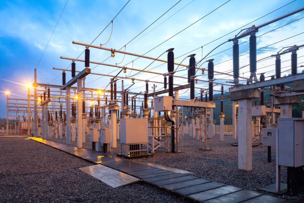
Electricity generation does not end when a generator produces electrical power. The generated electricity must be connected safely and efficiently to a transmission or distribution network, often requiring substantial voltage transformation. Without appropriately designed power transformers, generators would be forced to operate directly at unsuitable grid voltages, increasing current, losses, insulation requirements, and equipment constraints. Power transformers support electricity generation systems primarily by converting generator output voltage to the appropriate transmission or auxiliary-system voltage, while also providing electrical isolation, voltage control, impedance characteristics, and reliable power transfer. Step-up generator transformers are especially important because they raise generator voltage before transmission, allowing lower current and substantially reducing resistive losses in the network.
Generator transformers only increase voltage and have no other important function in a power generation system.False
Generator transformers primarily perform voltage transformation, but their impedance, insulation, grounding arrangement, cooling system, voltage regulation, protection, and electrical isolation also influence generator-grid performance and system reliability.
What Is the Role of a Transformer in a Power Plant?
A typical utility-scale generating station can be simplified as:
Prime mover → Generator → Generator transformer → Transmission network
The generator converts mechanical energy into electrical energy. The generator transformer then changes the voltage to a level suitable for transmission.
For example, a generator may produce electricity at a medium-voltage level while the transmission network operates at a substantially higher voltage.
The transformer creates the electrical interface between these two systems.
This arrangement allows the generator and transmission system to be designed around their respective engineering requirements rather than forcing the generator to operate directly at the transmission voltage.
Why Are Generator Transformers Usually Step-Up Transformers?
The primary reason is transmission efficiency.
For a three-phase system:
[S=\sqrt{3}VI]
For a given apparent power, increasing voltage reduces current.
Transmission-line resistive losses are approximately:
[P_{loss}=I^2R]
Therefore, raising generator voltage before sending power through long transmission lines can significantly reduce conductor losses.
For example, if voltage is increased by a factor of 5 while transmitted apparent power remains approximately constant, current decreases by a factor of 5. The theoretical resistive loss associated with the same conductor resistance then falls by approximately:
[5^2=25]
This illustrates why generator step-up transformers are fundamental to large-scale electricity generation.
The transformer relationship shown here illustrates the basic mechanism: changing the turns ratio changes the voltage level while an ideal transformer approximately preserves apparent power.
How Does a Generator Transformer Connect to the Grid?
The generator transformer is normally installed between the generator terminals and the high-voltage switchyard.
Its basic functions include:
- Increasing generator voltage
- Matching the transmission-network voltage
- Providing electrical isolation
- Establishing appropriate system impedance
- Supporting protection coordination
- Transferring generated power to the grid
The exact arrangement depends on the plant configuration.
A large generating station may contain several generating units, each connected through its own generator transformer, while other transformers supply station auxiliary loads.
How Does the Transformer Protect Generator Equipment?
The transformer itself is not a substitute for generator protection, but its electrical characteristics influence the protection system.
Transformer impedance affects fault-current levels.
A simplified relationship is:
[I{sc}\approx\frac{I{rated}}{Z_{pu}}]
where (Z_{pu}) represents the transformer impedance in per-unit form.
A lower impedance generally permits greater fault current, while higher impedance tends to limit fault current.
This affects the design and coordination of:
- Generator protection
- Transformer differential protection
- Circuit breakers
- Switchgear
- Busbar protection
- Overcurrent protection
Consequently, transformer impedance must be selected as part of the complete generator-grid protection study.
Why Is Transformer Capacity Important?
Generator-transformer capacity must be coordinated with generator output.
A transformer that is undersized can become a bottleneck between the generator and transmission system.
Excessive loading can cause:
- Higher winding temperature
- Increased load losses
- Greater voltage drop
- Reduced operating margin
- Accelerated insulation aging
- Restricted generator output
However, selecting excessive capacity also increases:
- Capital cost
- Physical size
- Transportation requirements
- No-load losses
- Installation requirements
The transformer should therefore be selected based on generator rating, operating profile, ambient conditions, future requirements, and allowable loading.
| Generator Requirement | Transformer Selection Consideration |
|---|---|
| Rated MW/MVA | Transformer continuous MVA rating |
| Generator terminal voltage | Transformer low-voltage winding rating |
| Grid voltage | High-voltage winding rating |
| Power factor | Current and regulation requirements |
| Generator operating range | Tap and voltage-control requirements |
| Fault level | Transformer impedance |
| Ambient temperature | Cooling and thermal design |
| Installation altitude | Insulation and cooling corrections |
| Future expansion | Capacity margin |
| Grid connection requirements | Protection and testing |
How Does Power Factor Affect Generator Transformer Performance?
Generator output is often specified in MVA rather than MW because transformer windings and other electrical equipment are primarily limited by current and insulation conditions.
For a three-phase system:
[I=\frac{S}{\sqrt{3}V}]
The same MVA rating therefore determines approximately the same current at a given voltage, regardless of whether the real-power component changes.
Power factor nevertheless matters for:
- Generator operation
- Voltage regulation
- Reactive-power flow
- Grid voltage control
- Transformer loading interpretation
If the generator supplies or absorbs significant reactive power, the transformer must be suitable for the resulting operating conditions.
How Does Voltage Regulation Affect Generator-Grid Operation?
A generator transformer has internal resistance and leakage reactance.
Its equivalent impedance can be represented as:
[Z{eq}=R{eq}+jX_{eq}]
When current flows, these components produce internal voltage drops.
The resulting regulation depends on:
- Transformer impedance
- Generator output current
- Power factor
- Tap position
- Temperature
- Operating condition
For a generating station, voltage regulation is important because generator terminal voltage and grid voltage must remain within their required operating ranges.
A transformer with inappropriate impedance characteristics may contribute to undesirable voltage variation during changing operating conditions.
Why Is the Cooling System Important?
A generator transformer operates continuously under significant electrical loading.
Transformer losses are converted into heat.
Two major loss categories are:
No-load losses, which occur whenever the transformer is energized.
Load losses, which increase with current and include winding copper losses and additional stray losses.
Winding copper loss approximately follows:
[P_{cu}=I^2R]
Therefore, the cooling system must remove heat effectively enough to keep winding and insulation temperatures within specified limits.
Common large-transformer cooling arrangements include:
- ONAN
- ONAF
- OFAF
- Other forced-oil or forced-air configurations
The correct cooling arrangement depends on transformer rating, load cycle, ambient conditions, and required overload capability.
Why Is Insulation So Important for Generator Transformers?
Generator transformers are connected directly to high-energy electrical systems and may experience severe electrical stresses.
The insulation system must withstand:
- Continuous operating voltage
- Lightning impulses
- Switching surges
- Temporary overvoltages
- Thermal aging
- Mechanical forces
- Environmental exposure
High-voltage bushings are particularly important because they provide the electrical interface between transformer windings and external conductors.
Insulation coordination must therefore consider the generator voltage, transmission voltage, system grounding, surge protection, and applicable insulation levels.
How Do Generator Transformers Handle Auxiliary Power?
A power plant itself consumes electricity.
Large generating facilities may require power for:
- Pumps
- Fans
- Cooling systems
- Control systems
- Lighting
- Motors
- Water treatment
- Instrumentation
- Protection equipment
Station-service or auxiliary transformers supply these loads.
During normal operation, auxiliary power may be supplied from the plant's own generation system. During startup or shutdown, the power source may come from the external grid.
Therefore, transformers support not only the export of electricity but also the internal operation of the generating facility.
How Do Transformers Support Generator Startup?
A generator cannot always supply its own auxiliary loads before it reaches operating condition.
Many power plants therefore use auxiliary transformers to provide power for startup systems.
The sequence can involve:
Grid power → auxiliary transformer → station equipment → generator startup → generator transformer → grid export
This demonstrates why a power-generation project may require multiple transformer types rather than a single large generator transformer.
What About Renewable Generation?
Power transformers are equally important in modern renewable-energy facilities.
Solar and wind projects often use power-electronic converters before connecting to the grid.
Transformers may be required to:
- Raise collector-system voltage
- Connect inverter output to medium-voltage networks
- Interface with transmission systems
- Provide appropriate impedance
- Support grounding arrangements
- Manage thermal loading
- Accommodate variable power flow
Renewable projects can also present unusual operating profiles, including rapid changes in power output and increased harmonic considerations.
Transformer specifications should therefore account for the characteristics of the associated inverter or converter system.
How Do Transformers Support Grid Stability?
A generator transformer is part of the electrical path between the generator and the grid.
Its impedance affects power-system calculations involving:
- Fault current
- Voltage stability
- Power flow
- Protection
- Parallel generation
- Reactive-power behavior
Its physical design also affects the transformer's ability to withstand mechanical forces during faults.
Therefore, transformer selection must be coordinated with generator and grid studies rather than performed independently.
What Should Buyers Specify for Generator Transformers?
For a generator transformer, buyers should establish a detailed technical specification.
Important parameters include:
- Rated MVA
- Generator-side voltage
- Grid-side voltage
- Frequency
- Vector group
- Percentage impedance
- Resistance/reactance characteristics
- Tap range
- Cooling class
- Insulation levels
- Short-circuit withstand capability
- Temperature-rise limits
- No-load losses
- Load losses
- Environmental conditions
- Bushings and connection arrangements
- Protection and monitoring
- Factory testing requirements
These parameters should be coordinated with the generator manufacturer, grid operator, EPC contractor, and protection engineer.
How Can Buyers Verify Generator-Transformer Quality?
Factory testing is particularly important for large generator transformers because transportation, installation, and replacement can be expensive and time-consuming.
Buyers should typically review applicable routine and type-test documentation covering parameters such as:
- Winding resistance
- Voltage ratio
- Impedance
- Load losses
- No-load losses
- Insulation performance
- Dielectric tests
- Temperature-related data
- Auxiliary equipment
- Protection and monitoring functions
The exact test program should follow the applicable technical standards and project specification.
How Do Power Transformers Improve Efficiency in Power Transmission Networks?
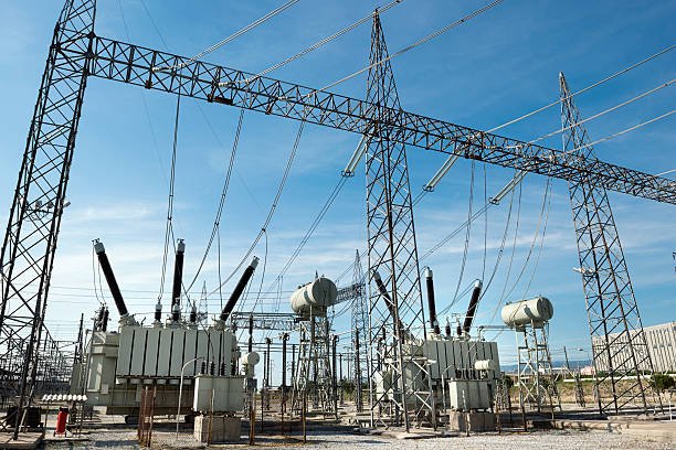
Electricity must often travel hundreds of kilometers from generating stations to major load centers. If large amounts of power were transmitted at relatively low voltage, the required current would become very high, increasing conductor heating, voltage drop, and energy losses. Power transformers improve transmission efficiency primarily by stepping voltage up before long-distance transmission and stepping it down at substations and distribution points. For approximately the same transmitted power, higher voltage means lower current, while conductor losses are proportional to (I^2R). By reducing current, transformers significantly reduce resistive transmission losses, improve the utilization of conductors, and make long-distance transfer of large amounts of electricity economically practical.
Power transformers improve transmission efficiency mainly by increasing voltage so that less current is required to transmit the same amount of power.True
For a given power transfer, increasing voltage reduces current. Since resistive conductor losses approximately follow I²R, reducing current can substantially reduce transmission losses.
Why Is High Voltage More Efficient for Power Transmission?
The fundamental relationship is straightforward.
For a simplified three-phase system:
[P=\sqrt{3}VI\cos\phi]
where (P) is real power, (V) is line voltage, (I) is line current, and (\cos\phi) is power factor.
If the required transmitted power remains approximately constant, increasing the transmission voltage allows the current to decrease.
This is important because the electrical resistance of transmission conductors causes heat losses:
[P_{loss}=I^2R]
The square relationship is the critical point. A reduction in current produces a disproportionately larger reduction in resistive loss.
For example, if current is reduced by 50%, conductor (I^2R) losses theoretically fall to 25% of their previous value, assuming resistance remains unchanged.
A power transformer makes this voltage-current conversion practical. The step-up transformer raises voltage before transmission, while a step-down transformer later reduces voltage to appropriate network and utilization levels.
How Does a Step-Up Transformer Reduce Transmission Losses?
A generator may produce electricity at a voltage that is practical for the generator terminals but not optimal for long-distance transmission.
A generator step-up transformer increases this voltage before the electricity enters the transmission network.
The simplified sequence is:
Generator → Step-up transformer → High-voltage transmission line → Receiving substation → Step-down transformer → Distribution network
For approximately conserved apparent power:
[S\approx VI]
Increasing (V) therefore reduces (I).
Suppose a network needs to transfer 100 MW. If the transmission voltage is increased significantly, the current required to transfer that power decreases. Lower current reduces heating in conductors and allows the same transmission infrastructure to carry large amounts of power more efficiently.
This is one of the most important reasons modern electrical grids use high-voltage and extra-high-voltage transmission.
Why Are Conductor Losses So Important?
Every transmission line has resistance. Even high-quality aluminum or copper conductors cannot eliminate it.
When current flows through the conductor, electrical energy is converted into heat.
The approximate loss is:
[P_{loss}=I^2R]
Consider a simplified line with resistance of 10 Ω.
At 1,000 A:
[P_{loss}=1{,}000^2\times10=10,MW]
If the current is reduced to 500 A:
[P_{loss}=500^2\times10=2.5,MW]
The current has only been reduced by half, but the theoretical resistive loss has fallen by 75%.
This illustrates why increasing transmission voltage is so effective.
Do Power Transformers Eliminate Transmission Losses?
No.
Transformers themselves consume energy, so the goal is to reduce total system losses, not eliminate losses completely.
Transformer losses generally include:
No-load losses: primarily core-related losses that occur whenever the transformer is energized.
Load losses: primarily winding copper losses and additional stray losses that increase as current increases.
Winding loss approximately follows:
[P_{cu}=I^2R]
A well-designed transmission system therefore considers both transformer losses and line losses.
The energy saved by transmitting at high voltage must be greater than the energy consumed by the transformers and associated equipment.
Modern power transformers are designed with optimized magnetic cores, windings, cooling systems, and insulation to keep their own losses relatively low.
How Do Transformer Core Materials Affect Efficiency?
The transformer's core is continuously magnetized and demagnetized during AC operation.
This creates magnetic losses, mainly:
- Hysteresis loss
- Eddy-current loss
Grain-oriented electrical steel is commonly used in power-transformer cores because its magnetic characteristics can be optimized for the direction of flux.
Amorphous metal can provide even lower no-load losses in suitable applications.
Core efficiency is also influenced by manufacturing quality.
Important factors include:
- Lamination thickness
- Core-joint construction
- Magnetic flux density
- Cutting accuracy
- Burr control
- Core clamping
- Insulation between laminations
A high-quality material cannot deliver its theoretical benefit if core manufacturing is poorly controlled.
How Do Transformer Windings Influence Efficiency?
Windings carry the operating current and therefore contribute significantly to load losses.
Winding design must consider:
- Conductor cross-sectional area
- Conductor material
- Current density
- Winding geometry
- Stray magnetic fields
- Cooling channels
- Insulation system
If current density is unnecessarily high, conductor losses and temperature rise can increase.
A well-designed winding balances conductor material, electrical performance, thermal performance, mechanical strength, and manufacturing cost.
For large power transformers, winding design also has to withstand mechanical forces generated during short-circuit conditions.
How Does Transformer Impedance Affect Efficiency?
Transformer impedance is represented approximately by:
[Z{eq}=R{eq}+jX_{eq}]
The resistive component contributes directly to losses.
The leakage-reactance component primarily affects voltage regulation and short-circuit current.
Impedance therefore creates an important design balance.
Lower impedance can provide tighter voltage regulation but may allow higher fault currents.
Higher impedance can limit fault current but may produce greater voltage drop under load.
Consequently, buyers should not assume that the transformer with the lowest impedance is automatically the most efficient or desirable.
How Does Power Factor Influence Transmission Efficiency?
Power factor has a direct effect on transmission current.
For a three-phase system:
[I=\frac{P}{\sqrt{3}V,PF}]
For the same real power and voltage, a lower power factor requires higher current.
Because line losses are approximately proportional to (I^2R), poor power factor can increase losses.
For example, improving power factor from 0.80 to 0.95 reduces the current required for the same real-power transfer.
This can reduce:
- Transmission-line losses
- Transformer loading
- Conductor heating
- Voltage drop
- Required electrical capacity
Therefore, transformer efficiency should be evaluated together with the power factor of the network rather than independently.
How Do Transformers Help Control Voltage?
Transmission systems must maintain voltage within acceptable limits.
As current flows through transformer impedance, the terminal voltage can change with loading.
Voltage regulation depends on:
- Transformer impedance
- Load current
- Power factor
- Temperature
- Tap position
For an approximate lagging load:
[VR\approx R{pu}\cos\phi+X{pu}\sin\phi]
Transformers equipped with suitable tap-changing systems can compensate for changing network conditions.
On-load tap changers can adjust the effective turns ratio while the transformer remains energized.
This is particularly valuable at major substations where voltage conditions vary with:
- Load demand
- Generation dispatch
- Reactive power
- Transmission-line loading
- Network configuration
Does Higher Transformer Capacity Always Improve Efficiency?
Not necessarily.
Transformer capacity should match the actual load profile.
An undersized transformer may operate close to its thermal limit, increasing load losses and accelerating aging.
An excessively oversized transformer, however, may operate at low utilization for much of its service life while continuing to produce no-load losses.
For lifecycle efficiency, buyers should evaluate:
| Operating Factor | Efficiency Consideration |
|---|---|
| Average load | Influences long-term load losses |
| Peak load | Determines thermal and voltage requirements |
| Load duration | Determines accumulated energy losses |
| Future growth | Prevents premature overloading |
| No-load operating hours | Makes core loss important |
| Power factor | Determines current demand |
| Ambient temperature | Influences cooling requirements |
| Redundancy | Affects transformer utilization |
The optimum transformer is therefore not necessarily the largest transformer.
How Do Transformers Support Renewable-Energy Transmission?
Renewable-energy projects are increasingly located far from major consumption centers.
Large solar and wind facilities may generate electricity in areas with excellent renewable resources but relatively low local demand.
Power transformers allow this electricity to be stepped up and transferred efficiently to distant load centers.
They are also important in:
- Solar farms
- Wind farms
- Battery energy-storage systems
- Hybrid renewable plants
- Grid-forming inverter systems
- Distributed-generation networks
These projects can introduce variable power flow and significant power-electronic equipment.
Consequently, transformer specifications may need to consider:
- Harmonics
- Reactive-power behavior
- Rapid load changes
- Thermal cycling
- Voltage regulation
- Insulation
- Cooling
- System impedance
How Should Buyers Compare Transformer Efficiency?
Buyers should request specific guaranteed loss values instead of relying on general claims such as “high efficiency” or “low-loss transformer.”
A useful comparison includes:
| Specification | Why Buyers Should Review It |
|---|---|
| No-load loss | Represents continuous core energy consumption |
| Load loss | Indicates winding and additional load-related losses |
| Rated MVA | Defines maximum intended loading |
| Percentage impedance | Influences voltage drop and fault current |
| Power factor | Determines current for a given real-power transfer |
| Core material | Influences no-load losses |
| Winding design | Influences load losses and thermal performance |
| Cooling system | Controls operating temperature |
| Tap changer | Supports voltage control |
| Guaranteed tolerances | Defines acceptable manufacturing variation |
| Factory test results | Verifies actual performance |
The most meaningful comparison is based on the transformer's actual expected operating profile.
Why Should Lifecycle Cost Matter More Than Purchase Price?
A transformer may operate for several decades.
Its purchase price is therefore only one part of its total cost.
A simplified lifecycle-cost model can be expressed as:
[LCC=C{purchase}+C{installation}+C{losses}+C{maintenance}+C_{outage}]
The energy-loss component can become particularly significant for continuously energized utility transformers.
A transformer with a higher initial price but lower guaranteed losses may provide a better economic result over its service life.
Buyers should therefore consider:
- Electricity price
- Annual operating hours
- Average loading
- Peak loading
- Expected service life
- Discount rate
- No-load losses
- Load losses
- Maintenance requirements
This approach converts transformer efficiency from a marketing claim into a measurable financial parameter.
How Do Power Transformers Enable Reliable Electricity Distribution?

Electricity distribution must deliver power from substations to homes, commercial buildings, factories, and other loads while keeping voltage within acceptable limits and equipment operating safely. If distribution voltage is poorly controlled, transformers are overloaded, or protection is inadequate, customers can experience voltage fluctuations, overheating, outages, or equipment damage. Power transformers enable reliable electricity distribution by stepping transmission and sub-transmission voltages down to appropriate distribution levels while providing controlled voltage transformation, electrical isolation, impedance, thermal management, and compatibility with protection systems. Their capacity, voltage ratio, impedance, insulation, cooling, tap-changing capability, and environmental protection all contribute to maintaining a stable and dependable supply.
Power transformers improve electricity distribution reliability only by changing voltage levels.False
Voltage transformation is fundamental, but transformer impedance, insulation, cooling, tap changing, protection, monitoring, capacity, and environmental design also strongly influence distribution reliability.
What Role Do Transformers Play in Electricity Distribution?
A simplified distribution network can be represented as:
Transmission network → Substation transformer → Distribution feeder → Distribution transformer → Consumer
The transformer at the substation reduces the incoming high voltage to a level suitable for distribution feeders.
Additional distribution transformers then reduce the voltage again for final utilization.
This staged approach is important because one voltage level cannot efficiently and safely serve every part of an electrical network.
Transformers therefore provide the electrical interfaces that allow the grid to move from high-voltage transmission to medium-voltage distribution and finally to customer utilization voltage.
Why Is Voltage Transformation Important?
For a given power transfer:
[S=\sqrt{3}VI]
where (S) is apparent power, (V) is voltage, and (I) is current.
Higher voltage permits lower current for the same power transfer.
As electricity approaches consumers, the voltage must be reduced to practical levels. A distribution transformer performs this step-down function.
This allows the network to maintain efficient transmission and distribution while providing voltage levels appropriate for connected equipment.
The turns-ratio relationship shown here illustrates how transformers provide controlled voltage conversion between different parts of the power system.
How Do Transformers Help Maintain Stable Customer Voltage?
Customer voltage should remain within an acceptable operating range even when electrical demand changes.
Distribution loads can vary substantially during:
- Morning startup
- Working hours
- Evening peaks
- Seasonal periods
- Motor starting
- Heating or cooling operation
- Industrial production cycles
When transformer current changes, internal impedance produces a corresponding voltage drop.
A simplified transformer model is:
[Z=R+jX]
where (R) represents the resistive component and (X) represents leakage reactance.
The resulting voltage regulation depends on transformer impedance, load current, power factor, temperature, and tap position.
Proper transformer selection therefore helps maintain acceptable voltage at the consumer end of the feeder.
Why Is Transformer Capacity Important for Reliability?
Transformer capacity must match the expected distribution load.
If a transformer is consistently overloaded, several problems can occur:
- Winding temperature rises
- Insulation aging accelerates
- Load losses increase
- Voltage regulation deteriorates
- Protection may operate unnecessarily
- Transformer life can be reduced
A transformer with excessive capacity can also be inefficient economically because its no-load losses continue even when utilization is low.
Buyers should therefore consider both present demand and future load growth.
| Capacity Consideration | Reliability Impact |
|---|---|
| Normal load | Determines typical thermal loading |
| Peak load | Determines maximum operating stress |
| Load growth | Prevents premature overload |
| Motor starting | Helps avoid temporary voltage dips |
| Seasonal demand | Supports summer/winter loading |
| Transformer redundancy | Improves continuity during outages |
| Ambient temperature | Influences available cooling capacity |
How Do Transformer Impedance and Voltage Regulation Work Together?
Transformer impedance is one of the most important electrical parameters for distribution applications.
Lower impedance generally means lower voltage drop under load, but it can also allow higher fault current.
Higher impedance can limit fault current but may increase voltage variation.
Therefore, the ideal impedance depends on the distribution network.
A buyer should consider:
- Feeder length
- Feeder conductor size
- Expected fault current
- Motor loads
- Protection settings
- Parallel transformer operation
- Required voltage regulation
Transformer impedance should be coordinated with the complete distribution-system study rather than selected from a generic catalog value.
How Do Tap Changers Improve Distribution Reliability?
Tap changers allow the transformer ratio to be adjusted to compensate for voltage variation.
Depending on the application, a transformer may use:
- Off-circuit taps
- On-load tap changers
An OLTC can adjust voltage while the transformer remains energized.
This can help compensate for changing system conditions and maintain a more stable distribution voltage.
For distribution networks with significant daily load variation, voltage control can be especially valuable.
However, tap-changing equipment adds cost, mechanical complexity, and maintenance requirements, so it should be specified according to the actual voltage-control requirement.
Why Is Cooling Important?
Transformer losses generate heat.
If heat is not removed effectively, winding and insulation temperatures increase.
The major operating losses include:
Core losses, which occur whenever the transformer is energized.
Load losses, which increase as current rises.
Winding copper losses approximately follow:
[P_{cu}=I^2R]
A suitable cooling system keeps the transformer within its permitted temperature-rise limits.
For larger distribution and substation transformers, cooling may involve natural oil circulation, forced air, forced oil, or combinations of these methods.
Correct cooling selection improves thermal reliability and helps preserve insulation life.
How Does Insulation Affect Distribution Reliability?
Distribution transformers are exposed to electrical stresses from normal operation, switching, and external events.
The insulation system must withstand:
- Continuous voltage
- Temporary overvoltage
- Switching surges
- Lightning impulses
- Thermal aging
- Moisture
- Contamination
Bushings, winding insulation, transformer oil where applicable, and solid insulation materials must work together.
Moisture is particularly important because it can accelerate insulation deterioration and reduce dielectric strength.
For outdoor transformers, sealing and moisture control are therefore essential design considerations.
How Do Protection Systems Prevent Transformer Failures?
A transformer should not be treated as an isolated asset.
Protection systems help detect abnormal conditions and disconnect faulty equipment before damage becomes severe.
Depending on transformer size and application, protection may include:
- Overcurrent protection
- Differential protection
- Overtemperature protection
- Oil-level monitoring
- Pressure protection
- Buchholz protection for suitable oil-filled designs
- Surge arresters
- Ground-fault protection
The exact configuration depends on transformer construction, rating, voltage level, and applicable standards.
Effective protection reduces the probability that a transformer fault will develop into a larger distribution-system outage.
How Do Surge Protection and Grounding Help?
Lightning and switching events can produce transient overvoltages.
Distribution transformers therefore commonly work together with surge-protection equipment such as metal-oxide surge arresters.
Grounding is equally important.
A properly engineered grounding system helps establish predictable fault-current paths and supports:
- Personnel safety
- Surge protection
- Protection-system operation
- Transformer neutral management
- System stability
Transformer grounding arrangements should be coordinated with the distribution network rather than specified independently.
How Do Environmental Conditions Influence Transformer Reliability?
Distribution transformers can be installed in many environments.
Examples include:
- Coastal areas
- High-humidity regions
- Desert climates
- Industrial zones
- Polluted urban areas
- Cold climates
- High-altitude locations
Environmental conditions influence:
- Cooling performance
- Insulation
- Corrosion
- Sealing
- Bushing selection
- Enclosure requirements
- Materials
- Maintenance intervals
For example, a transformer installed near a coast may require enhanced corrosion protection, while a transformer in a hot climate may require additional cooling consideration.
How Do Dry-Type Transformers Support Reliable Indoor Distribution?
Dry-type transformers are frequently used in:
- Commercial buildings
- Hospitals
- Data centers
- Industrial facilities
- High-rise buildings
- Indoor substations
They eliminate the need for conventional liquid insulation and can offer advantages where fire risk, indoor installation, or environmental considerations are important.
However, their cooling and enclosure design must match the installation environment.
For heavily loaded industrial applications, buyers should carefully evaluate thermal performance, ventilation, ambient temperature, and harmonic loading.
How Do Oil-Filled Transformers Support Outdoor Distribution?
Oil-filled transformers remain widely used in outdoor substations and distribution systems because insulating liquid provides both dielectric insulation and heat-transfer capability.
Their specification may include:
- Mineral oil or alternative insulating fluid
- Conservator system
- Radiators
- Cooling equipment
- Oil-level monitoring
- Pressure-relief devices
- Sealing systems
- Fire protection
For environmentally sensitive applications, natural ester fluids may also be considered where their performance and operating conditions are appropriate.
How Do Transformers Reduce Distribution Energy Losses?
Transformers themselves have losses, but appropriate voltage selection reduces current and therefore conductor losses.
Transformer efficiency can be considered approximately as:
[\eta=\frac{P{out}}{P{out}+P_{loss}}]
A well-designed transformer minimizes:
- Core loss
- Winding loss
- Stray loss
At the system level, efficient transformer selection can reduce the energy wasted during continuous operation.
For buyers, both transformer losses and downstream feeder losses should therefore be considered.
Why Is Maintenance Important?
Transformer reliability depends not only on initial design but also on condition throughout its service life.
Maintenance and monitoring can identify:
- Oil deterioration
- Moisture ingress
- Abnormal temperature
- Bushing deterioration
- Loose connections
- Insulation aging
- Partial-discharge concerns
- Mechanical problems
For larger oil-filled transformers, diagnostic techniques may include oil testing and dissolved-gas analysis.
Condition monitoring can help utilities identify developing problems before an unexpected failure causes an outage.
How Can Buyers Evaluate Distribution Transformer Reliability?
A practical procurement evaluation should include both electrical and mechanical characteristics.
| Parameter | Buyer Evaluation |
|---|---|
| Rated MVA/kVA | Match present and future demand |
| Voltage ratio | Confirm distribution-system compatibility |
| Impedance | Balance voltage regulation and fault current |
| Regulation | Verify acceptable loaded voltage |
| No-load loss | Important for continuously energized operation |
| Load loss | Important under normal and peak loading |
| Cooling | Match ambient and loading conditions |
| Insulation | Match system voltage and surge environment |
| Tap range | Determine voltage-control capability |
| Protection | Verify fault and abnormal-condition protection |
| Environmental design | Consider humidity, pollution and corrosion |
| Monitoring | Match transformer importance and outage consequences |
| Testing | Require appropriate factory and acceptance testing |
What Is the Key to Reliable Transformer-Based Distribution?
Reliable electricity distribution does not depend on one transformer specification.
It results from the interaction of:
Correct voltage ratio + adequate capacity + suitable impedance + effective cooling + strong insulation + appropriate protection + environmental compatibility + condition monitoring
If any one of these areas is poorly specified, overall reliability can suffer.
For example, a transformer with excellent electrical efficiency can still have a shortened service life if its cooling system is inadequate for the local ambient temperature. Similarly, a properly rated transformer can experience avoidable failures if moisture control or surge protection is insufficient.
How Do Power Transformer Ratings and Designs Affect Power System Performance?
A power transformer is not simply a device that changes voltage. Its rated capacity, voltage ratio, impedance, losses, insulation, cooling system, winding configuration, and regulation characteristics all influence how effectively an electrical network operates. If a transformer is undersized, voltage can deteriorate and thermal stress can increase; if its impedance is poorly matched, fault currents and voltage regulation can become difficult to manage; and if its losses or cooling design are inappropriate, operating costs and service life can suffer. Power transformer ratings and designs affect power system performance by determining how much power can be transferred, at what voltage and current, with what voltage regulation, losses, fault-current behavior, thermal margin, and reliability. Correct transformer specification therefore supports efficiency, voltage stability, protection coordination, equipment life, and overall grid reliability.
A power transformer's MVA rating and voltage ratio are the only transformer specifications that significantly affect power system performance.False
MVA and voltage ratio are fundamental, but impedance, losses, cooling, regulation, insulation, vector group, tap range, winding design, and protection characteristics can also materially affect system efficiency, voltage behavior, fault levels, and reliability.
How Does Transformer Capacity Affect Power Transfer?
The transformer's MVA or kVA rating establishes the apparent-power level it can transfer under specified operating conditions.
For a three-phase system:
[S=\sqrt{3}VI]
where:
- (S) = apparent power
- (V) = line voltage
- (I) = line current
For a given voltage, a higher transformer rating generally means the transformer can carry more current and transfer more apparent power.
This makes capacity one of the most important parameters in system planning.
An undersized transformer can become a network bottleneck. During peak demand, it may operate close to its thermal limit, producing higher winding losses and temperature rise.
An oversized transformer provides greater capacity margin but may increase capital cost and physical footprint. It can also experience relatively high no-load energy consumption when operating at low utilization.
Therefore, the correct rating is not necessarily the largest available rating. It should reflect:
- Present load
- Peak demand
- Load duration
- Future growth
- Emergency loading requirements
- Parallel-transformer configuration
- System redundancy
How Does Voltage Rating Affect System Performance?
Transformer voltage ratings determine where the transformer can operate within the power system.
A transformer may connect:
Generator voltage → transmission voltage
or:
Transmission voltage → sub-transmission voltage
or:
Medium-voltage distribution → utilization voltage
The voltage ratio determines the transformation relationship:
[\frac{V_2}{V_1}\approx\frac{N_2}{N_1}]
where (N_1) and (N_2) represent winding turns.
Correct voltage selection is important because it affects:
- Current
- Insulation requirements
- Conductor loading
- Voltage drop
- Transmission losses
- Equipment compatibility
A transformer with an incorrect voltage ratio can create unacceptable operating conditions even if its MVA capacity is adequate.
Why Is Transformer Impedance So Important?
Transformer impedance is one of the parameters with the greatest influence on power-system behavior.
A simplified transformer impedance can be expressed as:
[Z=R+jX]
The resistance contributes to losses, while leakage reactance strongly influences voltage regulation and fault current.
During a short circuit, transformer impedance limits the current.
Approximately:
[I{sc}\approx\frac{I{rated}}{Z_{pu}}]
Therefore, lower impedance generally allows greater fault current, while higher impedance limits fault current.
This creates a system-level trade-off.
| Transformer Characteristic | Typical System Effect |
|---|---|
| Lower impedance | Better voltage regulation but higher fault current |
| Higher impedance | Lower fault current but potentially greater voltage drop |
| Higher resistance | Greater load losses |
| Lower resistance | Lower resistive losses |
| Appropriate impedance | Balanced voltage, fault and protection performance |
Transformer impedance must therefore be coordinated with switchgear ratings, protection settings, parallel operation, and network fault studies.
How Does Voltage Regulation Affect Power Quality?
When transformer load changes, terminal voltage changes because current flows through the transformer's internal impedance.
Voltage regulation is influenced by:
- Resistance
- Leakage reactance
- Load current
- Power factor
- Tap position
For an approximate lagging load:
[VR\approx R{pu}\cos\phi+X{pu}\sin\phi]
Good voltage regulation helps maintain customer and system voltage within acceptable limits.
Poor regulation can contribute to:
- Low-voltage conditions
- Excessive voltage variation
- Motor performance problems
- Increased equipment stress
- Reduced power quality
Transformer design must therefore reflect the characteristics of the connected load rather than relying only on nominal voltage.
How Do Tap Changers Improve System Performance?
Tap changers modify the transformer's effective turns ratio.
Common arrangements include:
- Off-circuit tap changers
- On-load tap changers (OLTC)
An OLTC can change the voltage ratio while the transformer remains energized.
This allows substations to compensate for changes in:
- Load
- Transmission voltage
- Reactive power
- Generation dispatch
- Network configuration
Tap-changing capability is especially important where voltage must be maintained tightly over a wide operating range.
However, OLTC systems introduce additional mechanical components and require appropriate control and maintenance.
How Do Transformer Losses Affect System Efficiency?
Transformers consume energy during operation.
The principal losses are:
No-load losses
These occur whenever the transformer is energized and are mainly associated with the magnetic core.
Load losses
These increase with current and include winding copper losses and additional stray losses.
Winding loss approximately follows:
[P_{cu}=I^2R]
Transformer efficiency can therefore be expressed as:
[\eta=\frac{P{out}}{P{out}+P_{loss}}]
A transformer with optimized core and winding design can reduce energy consumption over its operating life.
This is particularly important for continuously energized utility transformers, where even relatively small differences in losses accumulate over many years.
How Does Cooling Design Influence Transformer Performance?
Transformer losses become heat.
If the cooling system cannot remove this heat adequately, winding and insulation temperatures rise.
Excessive temperature accelerates insulation aging and can reduce service life.
Common cooling arrangements include:
- ONAN
- ONAF
- OFAF
- Forced-air cooling
- Other forced circulation arrangements
The appropriate cooling system depends on:
- Transformer rating
- Load profile
- Ambient temperature
- Installation altitude
- Required overload capability
- Installation environment
A transformer designed for a moderate climate may require different cooling provisions when installed in a high-temperature environment.
Although the interactive relationship above concerns energy stored by elevation rather than transformer heat directly, the broader engineering principle is useful: energy and its conversion pathways must be accounted for when evaluating physical systems. For transformer applications, electrical losses ultimately appear as heat that must be removed.
How Do Insulation and Dielectric Design Affect Reliability?
Transformer insulation must withstand both normal and abnormal electrical stresses.
Important stresses include:
- Continuous operating voltage
- Lightning impulses
- Switching surges
- Temporary overvoltages
- Thermal aging
- Mechanical stress
- Moisture
Insulation coordination affects the required:
- Winding insulation
- Bushings
- Clearances
- Surge arresters
- Oil or alternative insulating fluid
- Solid insulation system
As transformer voltage rating increases, insulation design becomes increasingly important.
A transformer can have excellent efficiency and adequate capacity but still suffer serious reliability problems if its insulation system is not properly matched to the network's voltage and transient environment.
How Does Winding Design Affect System Performance?
Winding construction affects more than current carrying capacity.
The winding design influences:
- Resistance
- Leakage reactance
- Temperature distribution
- Short-circuit strength
- Insulation stress
- Stray losses
- Mechanical stability
During a short circuit, very large electromagnetic forces can act on the windings.
Therefore, mechanical winding strength is an important part of transformer reliability.
Modern power transformers may use carefully designed disc, layer, or helical winding arrangements depending on the voltage and application.
Why Does Vector Group Matter?
The transformer's vector group defines the relationship between primary and secondary winding phase displacement and connection configuration.
It affects:
- Phase-angle relationships
- Grounding
- Parallel operation
- Zero-sequence behavior
- Protection
- System fault calculations
Two transformers cannot necessarily be operated in parallel simply because they have the same MVA and voltage ratings.
For parallel operation, important characteristics such as:
- Voltage ratio
- Vector group
- Polarity
- Percentage impedance
- Phase displacement
must be compatible.
This is why vector-group selection is a system-design issue rather than merely a transformer manufacturing detail.
How Does Transformer Design Affect Fault Performance?
Transformers are exposed to substantial electrical and mechanical stress during faults.
Transformer impedance influences fault current, while winding geometry and mechanical construction determine the transformer's ability to withstand resulting forces.
Protection systems must also detect and isolate faults appropriately.
Large transformers may use combinations of:
- Differential protection
- Overcurrent protection
- Ground-fault protection
- Pressure protection
- Temperature protection
- Oil-level monitoring
- Surge protection
The transformer's design and protection system should therefore be considered together.
How Do Environmental Conditions Affect Transformer Ratings?
A transformer's nominal rating does not automatically mean it can deliver the same performance under every environmental condition.
Important environmental factors include:
- Ambient temperature
- Installation altitude
- Humidity
- Pollution
- Dust
- Salt exposure
- Corrosion
- Ventilation
- Solar radiation
High ambient temperature can reduce cooling margin.
High altitude can reduce air density and influence cooling, while insulation clearances may also require consideration.
Humidity and pollution can increase external insulation risks.
Coastal environments may require improved corrosion protection and carefully selected external components.
How Do Transformers Influence Renewable-Energy Networks?
Modern electrical networks increasingly integrate:
- Solar generation
- Wind generation
- Battery storage
- Inverter-based resources
- Distributed generation
These resources may have variable output and different voltage characteristics from traditional synchronous generators.
Transformer design therefore needs to accommodate:
- Variable loading
- Bidirectional power flow
- Harmonics
- Reactive-power behavior
- Thermal cycling
- Voltage regulation
- Grid-code requirements
The transformer becomes an important interface between power-electronic equipment and the utility network.
How Should Buyers Evaluate Transformer Ratings and Designs?
Buyers should evaluate the transformer as part of the complete electrical system.
| Specification | Main Performance Question |
|---|---|
| MVA/kVA rating | Can it carry present and future demand? |
| Voltage ratio | Is it compatible with the network? |
| Frequency | Does it match the system frequency? |
| Impedance | Is voltage regulation and fault current acceptable? |
| No-load loss | Is continuous energy consumption acceptable? |
| Load loss | Are operating losses appropriate? |
| Cooling | Is sufficient thermal margin available? |
| Tap range | Is voltage control adequate? |
| Vector group | Is phase displacement suitable? |
| Insulation level | Can it withstand system and surge stresses? |
| Winding design | Is thermal and short-circuit strength sufficient? |
| Environmental protection | Is it suitable for the installation site? |
| Monitoring | Is condition monitoring appropriate? |
| Factory testing | Can performance be verified before shipment? |
The best specification balances technical performance, capital cost, operating cost, reliability, and expected service life.
How Can Buyers Select Power Transformers for Generation, Transmission, and Distribution Applications?

Choosing a power transformer is not simply a matter of matching an MVA number to a project load. A transformer used at a generating station has different priorities from one installed at a transmission substation or a distribution network, and selecting the wrong design can lead to excessive losses, poor voltage regulation, unnecessary capital costs, thermal stress, or shortened service life. Buyers should select power transformers by first defining the electrical duty and then matching MVA capacity, voltage ratio, impedance, vector group, insulation level, cooling, tap-changing capability, losses, environmental conditions, protection, and testing requirements to that duty. Generator transformers should prioritize generator-grid compatibility and high-power transfer; transmission transformers should emphasize system voltage, fault level, regulation, and grid stability; distribution transformers should emphasize reliable voltage delivery, efficient part-load operation, environmental suitability, and lifecycle cost.
A buyer can select a suitable power transformer by comparing only rated MVA and voltage.False
MVA and voltage are essential starting parameters, but transformer impedance, vector group, insulation, cooling, losses, tap range, fault withstand, environmental conditions, protection, installation requirements, and applicable standards must also be matched to the application.
The most useful way to approach transformer procurement is to begin with the role the transformer performs in the electrical network, rather than beginning with a preferred transformer model. The same nominal capacity can require substantially different construction depending on whether the transformer connects a generator to a transmission grid, interconnects two high-voltage systems, or supplies a distribution feeder. This distinction becomes especially important when comparing transformer quotations from different manufacturers, because two transformers with similar nameplate ratings may have different impedance, loss guarantees, cooling arrangements, insulation levels, accessories, tap ranges, and environmental capabilities. A technically lower-cost transformer may therefore become the more expensive choice if it produces higher lifetime losses or requires modifications to accommodate the system. Buyers should establish a clear technical specification before requesting quotations and should evaluate suppliers against the same baseline. This creates an apples-to-apples comparison and prevents important performance requirements from being hidden inside assumptions, exclusions, or optional accessories.
How Should Buyers First Identify the Transformer Application?
The first step is to determine where the transformer sits in the electrical system.
The three broad applications can be summarized as follows:
| Application | Primary Function | Main Selection Priorities |
|---|---|---|
| Generation | Connect generator output to the grid | Generator voltage, grid voltage, MVA, impedance, insulation, regulation, fault withstand |
| Transmission | Transfer power between high-voltage network levels | Voltage ratio, MVA, impedance, losses, OLTC, insulation, system stability |
| Distribution | Supply feeders and end users | kVA/MVA, secondary voltage, efficiency, regulation, cooling, environment, lifecycle cost |
A generator step-up transformer (GSU) normally receives power directly from a generator and raises the voltage to the transmission level. Because it sits between a generating unit and the grid, its design must be coordinated with generator terminal voltage, generator capability, system fault levels, protection philosophy, and grid requirements.
A transmission transformer generally connects different transmission or sub-transmission voltage levels. Its operating duty can include high continuous loading, changing power-flow direction, reactive-power variations, and significant fault stress. Such transformers often require sophisticated voltage-control and monitoring arrangements.
A distribution transformer is much closer to the customer load. It may operate for many years with highly variable loading, including long periods at relatively low utilization. Consequently, no-load loss, load loss, voltage regulation, environmental protection, and maintenance requirements become particularly important.
The basic transformer relationship is the starting point for all three applications, but the engineering requirements surrounding that relationship change substantially with the transformer's position in the network.
How Should Transformer MVA Capacity Be Selected?
Transformer capacity should be based on actual apparent-power demand, not simply real-power demand.
For a three-phase system:
[S=\sqrt{3}VI]
where (S) is apparent power in VA, (V) is line voltage, and (I) is line current.
If a generator is rated at a certain MVA, the generator transformer must normally be capable of transferring the required apparent power without exceeding its thermal limits. For transmission and distribution applications, buyers should additionally consider the expected load profile rather than selecting capacity only from today's peak demand.
A practical capacity assessment should consider:
- Normal continuous load
- Maximum expected load
- Emergency loading
- Seasonal loading
- Generator output profile
- Power factor
- Future load growth
- Parallel transformer operation
- Required redundancy
- Ambient temperature
- Cooling capability
Oversizing and undersizing both have disadvantages.
An undersized transformer may experience excessive loading, higher winding temperature, increased load losses, accelerated insulation aging, and restricted system capacity.
An oversized transformer provides greater capacity margin but usually costs more and may have unnecessarily high no-load losses relative to its utilization.
For continuously energized installations, the economic difference between transformer sizes should therefore be evaluated using the expected load curve.
How Does Voltage Selection Differ Among Generation, Transmission, and Distribution?
Voltage rating must correspond to the transformer's position in the electrical system.
A generator transformer might convert medium-voltage generator output to high-voltage transmission.
A transmission transformer may convert one high-voltage level to another.
A distribution transformer normally converts medium voltage to a lower utilization voltage.
The basic turns relationship is:
[\frac{V_2}{V_1}\approx\frac{N_2}{N_1}]
However, real transformer specification is more complicated because the rated voltage must also account for:
- System maximum voltage
- Insulation level
- Frequency
- Tap range
- Neutral connection
- Grounding arrangement
- Surge conditions
- Switching events
- Lightning exposure
Buyers should therefore distinguish between nominal system voltage and the transformer's complete insulation and operating specification.
How Important Is Transformer Impedance?
Transformer impedance is a critical purchasing parameter because it influences both normal operation and fault behavior.
A simplified equivalent impedance is:
[Z=R+jX]
The resistive component contributes to losses, while leakage reactance influences voltage regulation and fault current.
The approximate short-circuit current relationship is:
[I{sc}\approx\frac{I{rated}}{Z_{pu}}]
This means that a lower-per-unit impedance generally permits higher fault current.
That has consequences for:
- Circuit-breaker ratings
- Switchgear design
- Protection settings
- Busbar fault levels
- Generator fault studies
- Parallel transformer operation
A higher impedance can limit fault current but may increase voltage drop during loading.
Buyers should therefore avoid treating impedance as an isolated transformer parameter. It should be checked against the system short-circuit study and voltage-regulation requirements.
What Should Buyers Consider When Selecting Generator Transformers?
Generator transformers have a particularly demanding role because they form the direct electrical interface between the generating unit and the grid.
A buyer should establish:
- Generator rated MVA
- Generator terminal voltage
- Transmission-system voltage
- Frequency
- Generator power factor range
- Reactive-power operating range
- Transformer impedance
- Vector group
- Tap requirements
- Insulation levels
- Short-circuit withstand capability
- Cooling arrangement
- No-load losses
- Load losses
- Bushing requirements
- Generator and grid protection coordination
A GSU transformer should not be selected independently from the generator.
For example, the transformer's impedance can influence generator fault-current calculations. Its vector group can affect phase relationships and grounding. Its voltage ratio influences generator terminal conditions and grid compatibility. Its cooling capability determines how much power can be transferred under specified ambient conditions.
For large generating units, transformer reliability is particularly important because a transformer failure can remove an entire generation block from service.
What Should Buyers Consider When Selecting Transmission Transformers?
Transmission transformers generally require a strong focus on system integration.
Key questions include:
- What voltage levels are being interconnected?
- What is the maximum continuous MVA?
- What is the expected emergency loading?
- What is the system fault level?
- Is an OLTC required?
- What voltage regulation is required?
- Will transformers operate in parallel?
- What is the required insulation coordination?
- What are the expected environmental conditions?
- What monitoring system is appropriate?
Transmission transformers may also need advanced monitoring because their failure can affect a large geographical area.
Important monitoring equipment can include:
- Oil temperature indicators
- Winding temperature indicators
- Oil-level monitoring
- Pressure-relief devices
- Buchholz relays where applicable
- Online dissolved-gas monitoring
- Bushing monitoring
- Cooling-system alarms
- OLTC monitoring
The exact arrangement depends on transformer importance and project requirements.
What Should Buyers Consider When Selecting Distribution Transformers?
Distribution transformers have a different economic profile.
They may remain energized continuously for many years and experience highly variable loading.
For this reason, buyers should pay close attention to:
- No-load loss
- Load loss
- Part-load efficiency
- Voltage regulation
- Secondary voltage
- kVA rating
- Ambient temperature
- Harmonic loading
- Installation environment
- Maintenance requirements
- Fire and environmental considerations
A distribution transformer that operates at relatively low average load can accumulate substantial no-load losses over its lifetime.
Conversely, a transformer serving an industrial facility with high and relatively constant loading may place greater emphasis on load losses and thermal performance.
The load profile should therefore be part of the procurement specification.
How Do Core and Winding Designs Affect the Buying Decision?
Transformer efficiency and reliability depend heavily on core and winding construction.
Core design influences no-load losses through:
- Core material
- Lamination thickness
- Magnetic flux density
- Joint design
- Manufacturing accuracy
Grain-oriented electrical steel is widely used for conventional power-transformer cores.
Amorphous metal can be considered when particularly low no-load loss is important.
Winding design influences:
- Load loss
- Current density
- Temperature distribution
- Leakage reactance
- Mechanical strength
- Short-circuit withstand
- Stray losses
A buyer should therefore request guaranteed loss values rather than simply asking which core material is used.
Material names alone do not provide sufficient evidence of transformer performance.
How Should Buyers Evaluate Cooling Requirements?
Transformer cooling should be matched to both rating and installation environment.
Typical cooling classifications may include:
- ONAN
- ONAF
- OFAF
The appropriate arrangement depends on the required thermal capacity.
Buyers should also provide environmental information such as:
- Maximum ambient temperature
- Minimum ambient temperature
- Installation altitude
- Indoor or outdoor installation
- Solar exposure
- Ventilation
- Humidity
- Pollution
- Dust
- Coastal salt exposure
High ambient temperatures can reduce the available thermal margin. High altitude can affect both cooling and external insulation considerations.
A transformer designed without these conditions being clearly specified may not provide the expected continuous rating at the actual installation site.
How Do Tap-Changing Requirements Differ?
Tap-changing requirements depend on the network's voltage-control philosophy.
Off-circuit tap changers are relatively simple and generally require the transformer to be de-energized before adjustment.
On-load tap changers can adjust the effective ratio while energized.
OLTCs are particularly useful for transmission and substation applications where voltage changes continuously with system conditions.
For distribution applications with relatively stable voltage, a simpler tap arrangement may be sufficient.
Buyers should consider:
- Required tap range
- Number of tap positions
- Voltage-control accuracy
- OLTC duty
- Operating frequency
- Maintenance requirements
- Control integration
How Should Buyers Compare Transformer Losses?
Transformer efficiency should be evaluated using guaranteed test values.
The main categories are:
| Loss | When It Occurs | Procurement Importance |
|---|---|---|
| No-load loss | Transformer energized | Very important for continuous operation |
| Load loss | Transformer carrying load | Important for high-utilization applications |
| Stray loss | Associated with leakage flux and structural parts | Relevant to thermal and efficiency performance |
| Auxiliary consumption | Cooling/control equipment | Important for forced-cooling designs |
The simplified efficiency equation is:
[\eta=\frac{P{out}}{P{out}+P_{loss}}]
However, a single efficiency value does not tell the whole story.
A buyer should evaluate losses against the expected annual load curve.
For example, a transformer operating at low load most of the year may benefit significantly from lower no-load loss. A transformer operating close to rated capacity for long periods may place greater economic emphasis on load-loss performance.
How Should Buyers Consider Dry-Type Versus Oil-Filled Designs?
The application environment can determine whether dry-type or liquid-filled construction is more appropriate.
Dry-type transformers are commonly considered for:
- Indoor installations
- Commercial buildings
- Hospitals
- Data centers
- Industrial facilities
- Locations with specific fire-safety requirements
Oil-filled transformers are widely used for:
- Outdoor substations
- Utility networks
- Large industrial facilities
- Transmission applications
- High-capacity installations
Liquid-filled designs can provide effective heat transfer and high-power capability, while dry-type designs can offer advantages in certain indoor and fire-sensitive environments.
The selection should consider the complete installation rather than treating one construction as universally superior.
How Do Environmental Conditions Affect Transformer Selection?
Environmental conditions should be included in the technical specification from the beginning.
| Environmental Condition | Potential Design Response |
|---|---|
| High ambient temperature | Enhanced cooling/derating assessment |
| High altitude | Cooling and insulation evaluation |
| High humidity | Improved sealing and moisture control |
| Coastal salt | Corrosion-resistant materials/coatings |
| Industrial pollution | Appropriate external insulation |
| Dust | Enclosure and maintenance considerations |
| Outdoor exposure | Weather-resistant accessories |
| Fire-sensitive installation | Dry-type or alternative-fluid assessment |
| Severe cold | Low-temperature material and fluid considerations |
This is especially important because transformer accessories such as bushings, radiators, control cabinets, cable boxes, and monitoring devices can be more environmentally sensitive than the main tank.
How Should Buyers Evaluate Factory Quality?
Technical specifications should be supported by testing.
Depending on the application and applicable standards, buyers may require verification of:
- Winding resistance
- Voltage ratio
- Phase displacement
- Impedance
- No-load losses
- Load losses
- Dielectric performance
- Insulation resistance
- Temperature-related performance
- Tap-changer operation
- Protection and monitoring equipment
For large transformers, factory acceptance testing can be particularly valuable because replacement or repair after installation can be extremely costly.
Buyers should also review:
- Manufacturer experience
- Quality-control procedures
- Material traceability
- Core and winding manufacturing controls
- Drying and vacuum processes
- Sealing quality
- Factory test records
- Previous project references
How Can Buyers Compare Different Transformer Quotations?
A common procurement mistake is to compare only the initial equipment price.
A more useful comparison considers total ownership cost.
A simplified model is:
[LCC=C{purchase}+C{installation}+C{energy}+C{maintenance}+C_{outage}]
For a utility transformer, the cost of an unexpected outage can exceed the difference between two equipment quotations.
Buyers should therefore create a technical-commercial comparison matrix.
| Category | Supplier A | Supplier B | Supplier C |
|---|---|---|---|
| Rated capacity | Compare | Compare | Compare |
| HV/LV voltage | Compare | Compare | Compare |
| Impedance | Compare | Compare | Compare |
| No-load loss | Compare | Compare | Compare |
| Load loss | Compare | Compare | Compare |
| Cooling | Compare | Compare | Compare |
| Tap changer | Compare | Compare | Compare |
| Insulation level | Compare | Compare | Compare |
| Environmental rating | Compare | Compare | Compare |
| Protection | Compare | Compare | Compare |
| Factory testing | Compare | Compare | Compare |
| Warranty | Compare | Compare | Compare |
| Delivery | Compare | Compare | Compare |
| Lifecycle cost | Compare | Compare | Compare |
This method helps identify apparently inexpensive offers that actually exclude important accessories or provide less favorable performance guarantees.
What Is the Best Transformer Selection Strategy?
The most reliable procurement process can be organized into six stages:
1. Define the electrical duty.
Determine whether the transformer serves generation, transmission, sub-transmission, distribution, renewable generation, industrial loads, or another application.
2. Establish the operating envelope.
Specify capacity, voltage, frequency, power factor, load profile, ambient conditions, altitude, fault level, and future requirements.
3. Define the required transformer design.
Specify impedance, vector group, insulation level, cooling, tap range, core and winding requirements, accessories, and protection.
4. Establish measurable guarantees.
Require guaranteed no-load loss, load loss, impedance, temperature rise, and other project-critical values.
5. Verify manufacturing capability.
Evaluate the manufacturer's engineering experience, quality system, production controls, factory testing, and project references.
6. Compare lifecycle economics.
Consider purchase price together with energy losses, maintenance, reliability, outage consequences, and expected service life.
Conclusion
Power transformers are fundamental to every major stage of the electricity supply chain. They enable generators to deliver power at appropriate transmission voltages, support efficient long-distance electricity transfer, and reduce voltage to suitable levels for distribution and end users. Their reliability directly affects the stability and continuity of the broader power system. By selecting transformers with appropriate capacity, voltage ratings, insulation systems, cooling methods, and protection features, power-system operators can improve efficiency, minimize losses, and maintain dependable electricity supply over the transformer's long service life.
FAQ
Q1: How do transformers improve the efficiency of power transmission?
Transformers improve transmission efficiency primarily by allowing electrical power to be transmitted at higher voltages and correspondingly lower currents.
For a given amount of transmitted power, increasing voltage allows the required current to decrease, assuming other system conditions remain comparable. This is important because resistive losses in transmission conductors are strongly related to current.
The lower the current, the lower the conductor losses for a given transmission path.
For example, electricity generated at a relatively moderate generator voltage can be passed through a step-up transformer before entering a high-voltage transmission network. The higher transmission voltage makes long-distance power transfer more practical.
Near the destination, substations use step-down transformers to progressively reduce the voltage for regional and local networks.
This arrangement provides several benefits:
Reduced transmission losses
More economical conductor sizing
Greater transmission capacity
Improved long-distance power delivery
More flexible network interconnection
Transformer efficiency itself is also important. Although transformers are highly efficient electrical machines, they still experience core losses and load losses.
Core losses occur while the transformer is energized, whereas load-related losses increase as current and loading increase. These losses become heat and must be managed through the transformer's cooling system.
For large power transformers operating continuously for many years, even relatively small differences in losses can accumulate into substantial energy and financial impacts.
This is why utilities and industrial buyers often specify guaranteed no-load and load-loss values when purchasing transformers.
Transmission efficiency also depends on more than the transformer. Conductor resistance, line length, voltage level, reactive power, network configuration, and operating conditions all affect total system losses.
Nevertheless, the transformer provides the essential mechanism for moving between voltage levels that make efficient transmission possible.
Without step-up and step-down transformers, modern high-voltage transmission networks would be far less practical and significantly more difficult to operate economically.
Q2: What role do power transformers play in electricity distribution?
Power transformers play a crucial role in distribution by reducing electrical voltage from higher transmission or sub-transmission levels to voltages appropriate for local networks and consumers.
Electricity may travel through several voltage levels before reaching the final customer. At each stage, transformers provide the voltage conversion required by the next part of the network.
A typical system may include:
Generator transformer
Transmission transformer
Substation transformer
Distribution transformer
Service-level voltage transformation
The exact arrangement depends on the utility and network design.
Distribution transformers are particularly important because they bring electricity to usable voltage levels for residential, commercial, and industrial customers.
The transformer must maintain an appropriate output voltage even as the connected load changes. Its impedance, winding design, tap settings, and voltage-regulation characteristics therefore influence the quality of electricity delivered to customers.
Transformers also help utilities manage changing demand. Electricity consumption can vary substantially throughout the day, with peaks occurring when large numbers of customers use heating, cooling, lighting, industrial machinery, or other equipment.
A properly selected transformer must therefore provide sufficient capacity while avoiding unnecessary oversizing.
Distribution transformer selection can involve:
Rated capacity
Primary voltage
Secondary voltage
Phase configuration
Impedance
Efficiency
Cooling method
Environmental conditions
Expected load growth
Transformers are also increasingly important as distributed energy resources become more common. Solar photovoltaic systems, battery storage, electric vehicles, and other technologies can introduce power flows that differ from traditional one-way distribution models.
This can create new requirements for transformer capacity, voltage regulation, thermal performance, and monitoring.
Consequently, transformers are essential not only for reducing voltage but also for maintaining a reliable connection between high-voltage networks and local electrical loads.
Q3: How do power transformers support grid reliability and renewable energy integration?
Power transformers support grid reliability by connecting different voltage networks and enabling electricity to move where it is needed.
They are also becoming increasingly important as renewable energy changes how electricity is generated and transmitted.
Traditional power systems were largely designed around centralized generators that produced relatively predictable power flows. Renewable resources such as solar and wind can be more variable and may be located far from major consumption centers.
This creates a need for additional transmission infrastructure and transformer capacity.
For example, a large solar or wind project may generate electricity at a voltage that must be increased before power can enter a high-voltage transmission network. Generator step-up transformers perform this function.
Transformers are also used at substations to reduce voltage before electricity enters regional and local networks.
Their role in renewable integration includes:
Connecting renewable generators to transmission networks
Increasing voltage for long-distance transmission
Connecting different network voltage levels
Supporting changing power-flow patterns
Accommodating new generation capacity
Enabling grid expansion
Transformer specifications may need to account for operating conditions that differ from traditional generation.
Renewable projects can experience variable loading, frequent changes in power output, and different reactive-power characteristics. Transformer thermal design and voltage-control requirements must therefore be considered carefully.
Battery energy storage can also introduce bidirectional power flows. A transformer connected to an energy-storage system may operate differently during charging and discharging.
At the grid level, transformer reliability is particularly important because a failed high-capacity unit can create a major network constraint.
Utilities therefore invest in:
Condition monitoring
Preventive maintenance
Spare transformer strategies
Online diagnostic systems
Temperature monitoring
Oil and insulation analysis
Asset-management programs
As electrical grids become more decentralized and renewable generation expands, transformers will remain essential infrastructure for connecting new resources while maintaining dependable voltage conversion and power transfer.
Q4: What would happen if power transformers were not used in the electrical grid?
Modern electrical grids would be extremely difficult to operate without power transformers because generators, transmission networks, distribution systems, and end users generally require different voltage levels.
Without transformers, electricity could not be efficiently stepped up for long-distance transmission and then stepped down for distribution.
One consequence would be significantly higher current for transmitting the same amount of power at lower voltage. Higher current would increase resistive losses in conductors, creating greater energy waste and additional heating.
Long-distance transmission would consequently become less economical.
Another problem would be the inability to connect electrical equipment designed for different voltage levels. Generators, transmission networks, industrial equipment, distribution systems, and consumer loads would require much more complicated arrangements to operate together.
Transformers also provide important electrical isolation and help control how different parts of the network interact.
Their absence would affect:
Generation connections
Transmission networks
Distribution substations
Industrial power systems
Commercial buildings
Residential electricity supply
Renewable-energy projects
The problem would become even more significant as electricity demand grows and renewable generation expands.
Large renewable projects are often located far from major load centers. Efficiently transferring their output over long distances requires appropriate voltage transformation and high-voltage transmission infrastructure.
Transformers also help accommodate different network voltage levels without requiring every generator and load to operate at the same voltage.
In practical terms, the modern grid depends on transformers as fundamental interfaces between electrical systems.
Their importance is why transformer procurement, manufacturing quality, maintenance, spare-parts planning, and asset management are major concerns for utilities and industrial organizations.
A transformer is therefore much more than a device that changes voltage. It is a key infrastructure component that makes the interconnected power system technically practical, economically efficient, and adaptable to changing electricity-generation and consumption patterns.
References
IEC 60076 – Power Transformers
https://webstore.iec.ch/en/publication/602
IEC 60076-1 – Power Transformers: General
https://webstore.iec.ch/en/publication/603
IEC 60076-3 – Insulation Levels, Dielectric Tests and External Clearances
https://webstore.iec.ch/en/publication/605
IEEE Standards Association – Transformers and Electrical Power Standards
https://standards.ieee.org
U.S. Department of Energy – Electricity Delivery and Grid Systems
https://www.energy.gov/oe
U.S. Energy Information Administration – Electricity Explained
https://www.eia.gov/energyexplained/electricity/