
Why Must Transformers Be Synchronized?
Transformer synchronization is a critical requirement in power systems, especially when transformers operate in parallel or are connected to interconnected grids. Proper synchronization ensures that
A box-type substation is a fully enclosed and compact electrical distribution unit used in low and medium-voltage applications. It serves as a complete solution for the transformation and distribution of electrical power, providing both efficient and safe energy management. This substation integrates key electrical components such as transformers, circuit breakers, switchgear, and protection devices into a secure and pre-fabricated metal enclosure. Designed for urban and industrial settings, box-type substations ensure smooth and reliable electricity supply with minimal space and time requirements for installation.
Our box-type substation offers a safe, space-saving, and cost-effective energy distribution solution, featuring integrated components for efficient electrical transformation and protection. Easy to install and secure.
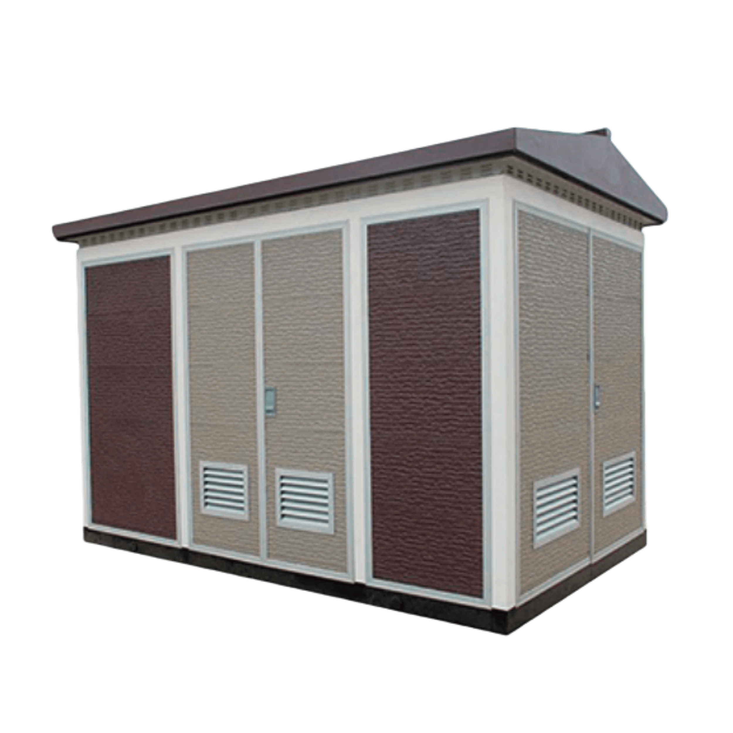
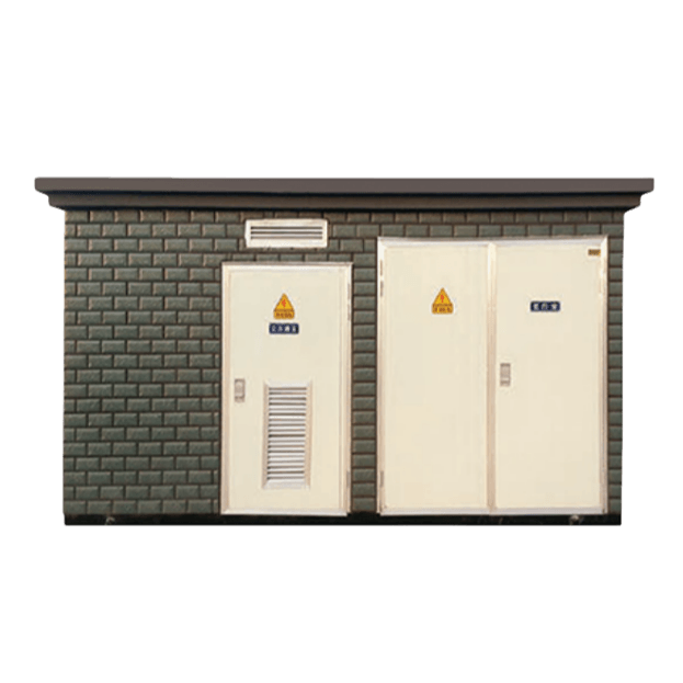
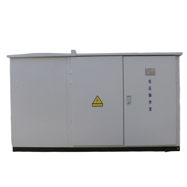
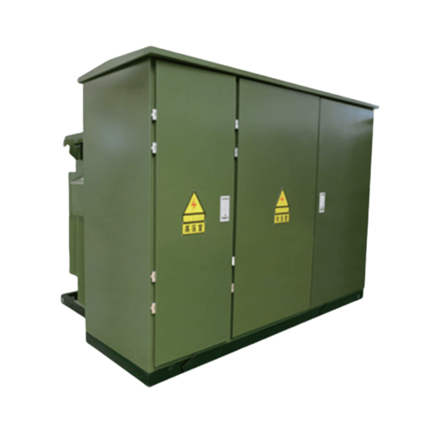
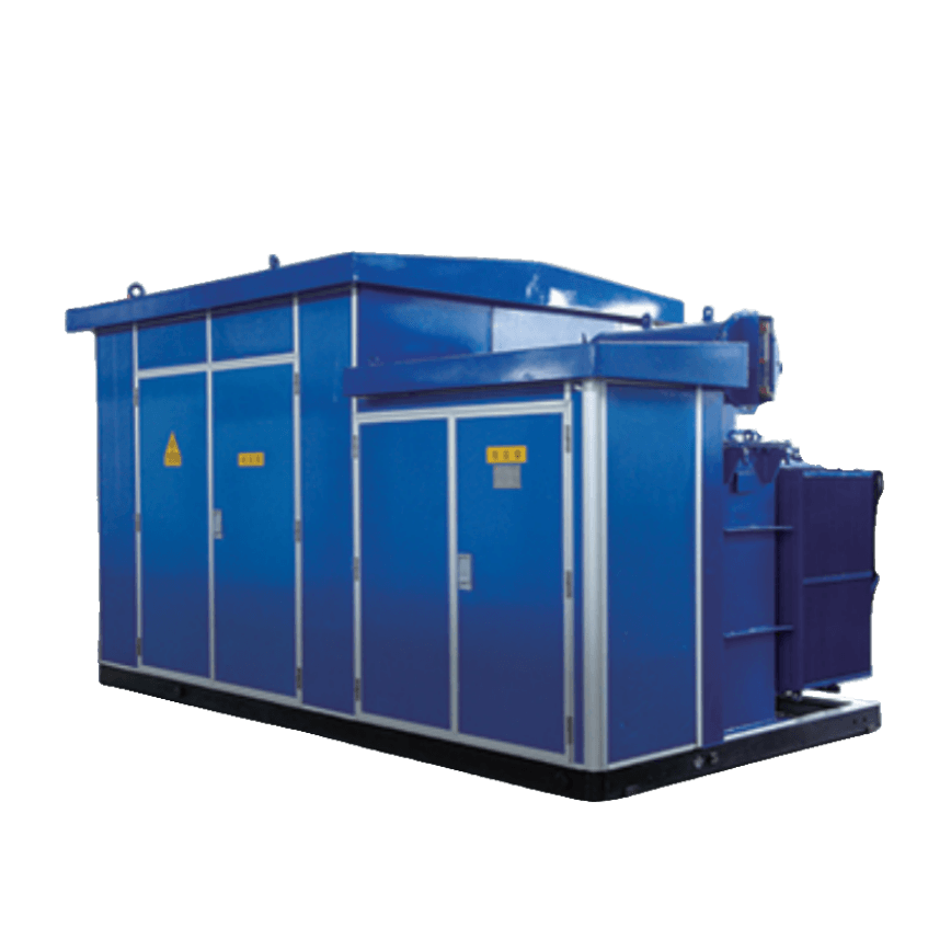
CBW box inverter booster (energy storage) integrated Step-up Equipment


Special Step-up Equipment for Photovoltaic Power Generation (American)

Box inverter boost integrated machine, energy storage integrated machine
Trusted by world-class brands & organizations of all sizes











The compartmental substation of CBW series is composed of HV and LV distribution equipment, transformer and outer shell and it can be used in grid and terminal distribution system. The compartmental substation is widely applied in industrial and mining enterprises, high buildings, residential zone, airport, high express way, port and some other places that needs power, illumination, and electricity transforming. The compartmental substation with the characteristics of small dimension, delicate structure, smooth running, easy maintain, low cost, deep to load center, short construction period etc.
Standard service environment of CBW series box type substation (European style)
Outdoor
Altitude is generally not more than 2000m; Ambient temperature is generally -30℃~+40℃; Wind speed is not greater than 35m/s; Air relative temperature is not more than 90% (+25℃); Seismic acceleration level: 0.4m/s² horizontal, 0.2m/s² vertical; Installation site not exist gas, vapor or other chemical substances that have serious effects on the conductor and insulation of the equipment and also free from fire and explosion hazard. The ground inclination does not exceed 5°.
When the above normal use conditions do not meet the requirements, the client can consult with the manufacturer to solve.
These substations are ideal for use in urban centers, industrial parks, airports, and commercial complexes, providing consistent power supply while minimizing space and operational complexities.
| Feature | American-style Box Transformer | European-style Box Transformer | Chinese-style Box Transformer (Hua-style) |
|---|---|---|---|
| Structure | Transformer, high-voltage load switch, and fuse placed inside the oil tank. | Transformer, high-voltage and low-voltage switchgear are housed in a single metal enclosure. | Similar to European style, but designed for larger capacities used in wind and solar power plants. |
| Cooling Method | Natural cooling through air, no oil conservator. The oil tank has a gas gap at the top. Cooling is done via natural ventilation, no forced cooling. | Forced ventilation is used, but cooling is difficult; high temperature reduces transformer output. | Forced ventilation and natural air cooling, combines American and European styles to address cooling difficulties. |
| Transformer Design | No oil conservator; oil tank and radiator are exposed to the air for cooling. | Transformer room is inside a sealed metal box, making heat dissipation difficult. | Transformer and oil tank are exposed to air for cooling, addressing heat dissipation issues effectively. |
| Protection & Safety | Simple protection; oil-immersed fuses and load switches, providing basic safety. | Comprehensive protection: visible disconnect points for high-voltage components, easy maintenance, and better safety. Equipped with isolation switches, grounding switches, load break switches, and circuit breakers. | Higher protection features for harsh environments (wind, solar); uses vacuum load switches, fuse protection, and visible disconnect points for safe maintenance. |
| Size | Small size due to the compact design and combined components inside the oil tank. | Larger size due to the separate high-voltage and low-voltage compartments. | Larger size, especially for wind/solar plants requiring higher capacities like 1600 kVA, 2200 kVA. |
| Land Area Requirement | Small land area needed due to compact design. | Larger land area required due to the bulkier design. | Requires significant land area for high-capacity models, especially in renewable energy (wind/solar). |
| Cost | Lower cost due to simpler design, fewer components, and lower manufacturing complexity. | Higher cost due to more complex design, additional components, and higher safety features. | Higher cost due to advanced components needed for harsh environments and larger capacities. |
| Maintenance | Easier to maintain because of simpler protection and all components being inside the oil tank. | Maintenance is more complex, but safer with visible high-voltage parts and easier to isolate. | More complex maintenance, but better suited for harsh environments with advanced protection and safety features. |
| Switchgear Operation | Typically manual operation, difficult to implement electric load switches. | Can have electric load switches for remote and automated operation. | Electric load switches supported, making it easy to operate remotely, especially in critical environments. |
| Impact of Power Outage | Larger outage area due to lack of separate high-voltage and low-voltage compartments. | Smaller outage area due to isolation switches that allow selective disconnection. | Smaller outage impact due to advanced protection and isolation systems. |
| Common Applications | Suitable for small to medium power needs, where space and cost are major considerations. | Typically used in medium to large power grids where protection, safety, and visibility are important. | Mainly used in wind and solar power applications, where cooling is critical and larger transformer capacities are needed. |
| Special Notes | – Simple, oil-immersed fuses and load switches. | – Requires forced ventilation due to the sealed design. | – Advanced cooling design for harsh environments like high temperature, high humidity, or salt fog. |
| Transformer Capacity | Typically smaller capacity. | Typically medium to large capacity, e.g., up to 630 kVA for State Grid. | Larger capacity, with wind power box transformers typically up to 1600 kVA, 2200 kVA. |
| Maintenance and Fault Isolation | Maintenance requires power outage; hard to isolate faults. | Fault isolation and maintenance can be done with minimal impact, as the high-voltage switchgear is accessible. | Fault isolation is more efficient, especially in environments with extreme conditions, thanks to enhanced isolation and protection. |
| High-Voltage Load Switch | Difficult to implement electric operation; typically manual. | Electric operation of the high-voltage load switch is possible, allowing for more automated control. | Electric operation of high-voltage load switches is available, suitable for remote control. |
| Fuse Type | Oil-immersed fuse and load switch. | Vacuum load break switch and current-limiting fuse. | Vacuum load break switch, current-limiting fuses, and improved protection for demanding environments. |
| No | Item | Unit | HV side | Transformer | LV side | ||||||||
| 1 | Rated capacity | kVA | 50-1600 | ||||||||||
| 2 | Rated voltage | kV | 12(6.3) | 10(6)0.4 | 0.4 | ||||||||
| 3 | Tap changer rated current | A | 630 | 70-2500 | |||||||||
| 4 | Rated Short-circuit Breaking Current(Rms) | KA | 31.5 | ≤400kVA 35 | >400kVA 50 | ||||||||
| 5 | Thermo stability time/thermostability current(Rms) | S/KA | 4/16 2/20 12 6.3 | 10 6 | 1/15 1/30 0.4 | ||||||||
| 6 | Insula- tion level | Rated voltage | kV | Interphase Phaseto ground | Fracture | Interphase Phase to ground | Fracture | Oil-immersed | Dry type | Oil-immersed | Dry type | Inter- phase | Phase to ground |
| 1 minute power frequency withstand voltage | |||||||||||||
| 42 | 48 | 32 | 36 | 35 | 28 | 2.5 | 2.5 | 2.5 | |||||
| Full wave lightning impulse withstand voltage | |||||||||||||
| 75 | 85 | 60 | 65 | 75 | 75 | ||||||||
| 7 | Noise | Oil-immersed transformer | dB | ≤50 | |||||||||
| Dry typetransformer | ≤55 | ||||||||||||
| 8 | Protection class | IP43 | |||||||||||
This product is connected by high-voltage power distribution devices, transformers and low-voltage power distribution devices and divided into three functional compartments, that is high voltage room, transformer room and low voltage room. High-voltage room with complete function that high-voltage room HXGN-12 ring network cabinet composed of a power supply system which can be arranged for ring network power supply, terminal power supply, dual power supply and other power supply, but also install HV metering components to meet the requirements of HV measurement. Transformers can choose SM11 and other low-loss oil-immersed transformers or dry-type transformers. The transformer is equipped with automatic forced air-cooling system and lighting system. The low-voltage room adopts the cabinet-type structure to meet the client’s power supply scheme including power distribution, lighting distribution, reactive power compensation, energy metering and other functions and facilitate the user’s power management and improve the quality of power supply.
The internal frame of the box-type substation is welded, shell with the double-layer color coated steel plate (the middle is the foam sandwich). The welding frame will be divided into high-voltage room, transformer room, low voltage room and integral lifting adopts lower part lifting mode of transformer substation. The box cover is covered with a ventilated structure with a thermal insulation layer to protect against the effects of solar radiation. There is a cooling inlet and outlet between the bottom of the box and each room, and air natural cooling and forced cooling air cooling device with automatic control form are adopted to ensure the normal operation of electrical equipment also increase the load factor of the transformer. Box exposed vents are taken filter structure to prevent dust, anti-small animals into the inside, without affecting the air circulation. This kind of structure has the characteristics of good rigidity, stronger anti-rust ability and beautiful appearance.
According to client’s needs, high voltage and low voltage room can be set up operating corridor or maintenance corridor, if necessary, can also set duty room.
In order to meet the needs of high humidity areas, combined substation can be equipped with temperature and humidity monitoring system.
Glass fiber resin pouring structure can achieve the same power frequency and impulse level as oil-immersed transformers, and some design structures have impulse levels exceeding 200kV.
The cast type transformer has already withstood the test voltage (HV to HV, HV to LV to ground) and operating voltage in the atmospheric environment. Wire winding inter-turn and inter-layer only have a tiny differential pressure, are absorbed by the resin itself, and reached a very safe level. The inter-layer voltage of the foil winding is only the minimum voltage of each turn, the end of the winding has no helical angle, the magnetic leakage area is small, and the axial short-circuit resistance is strong. As the air-based insulation, this part of the insulation system will not deteriorate, will not age.
The wire winding adopts vacuum casting to obtain a uniform insulation structure, eliminates bubbles and voids, and avoids partial discharge in the winding. The inter-layer voltage of the foil winding is low and no partial discharge.
According to the IEC60076 standard, partial discharge tests shall be carried out on fully assembled transformers. In order to confirm the high quality of the design and production, the partial discharge test of each HV winding is carried out before the assembly.
In this way, the insulation in the HV winding can be checked to meet the quality requirements. The partial discharge termination voltage is at least 1.2 times than the rated voltage, and in most cases, even 2 times than the rated voltage. It is proved by this test that the winding is qualified.
Glass fiber reinforced winding will not crack due to sudden fluctuations in temperature or thermal impulse.
Wire winding has been heated to the rated temperature, and then placed in ice water to cool for temperature change resistance test. All winding can pass such destructive tests.
Due to insulation and copper foil adhesive curing as a whole throughout the winding and the Foil winding is not cracking due to temperature fluctuations or sudden thermal shock.
According to Table III of the IEC 60076-5 standard, the maximum allowable average temperature of conductors after a short circuit for B, F, and H-class insulated copper wires is 350°C. For F-class copper winding transformers, the time “t” is determined, and after this duration, the final temperature will be:
T1 = T0 + a.Sk2.10–3[℃]
Among this:
The following is calculated by the upper figure:

As all protection devices can cut off the transformer power within 10 seconds, the margin shown in this example is very large.
When the transformer is short-circuited, the conductor is heated rapidly in a matter of seconds. The resin around it is better than the conductor, can only be slowly heated, the conductor and resin surface temperature gradient will be great, and the greater the thickness of resin wrapped, and its gradient is too large. Even when the expansion coefficient is well matched, the mechanical strength of the winding must be taken into account, but the elastic glass fiber resin structure can be used to prevent cracking under the above conditions.
The wire wound products are very well protected against moisture due to the copper conductor complete encapsulation in resin insulation. The transformer can be networked after long-term storage, and can be input into the power grid no-load.
The foil winding shall be stored in damp proof, and when the insulation resistance is lowered, it should be heated and dried before it can be put into use. When using, only compressed air can be used to remove sediment or dust.
The main concern of resin casting dry-type transformer is environmental protection. This question is actually a justification for the development of a cast type transformer:
The main feature of the resin casting transformer is flame retardant and self-extinguishing. Tests have shown that once a fault occurs inside the transformer and the protection device cuts off the transformer within the specified time, the winding itself will self-extinguish, thereby stopping the fire. If the external environment catches fire and all equipment and buildings are on fire, the epoxy resin may also burn, but the burning of the resin will not promote the spread of the fire.
The toxic components of combustion products are a major concern. Simulated tests were conducted in laboratories. Depending on the conditions and analysis methods, the results vary. According to OSHA requirements, if toxic substances are present, their concentrations are very low, allowing for prolonged exposure without harm.
In the wire wound transformer, the winding is not mechanically connected with the core, but the support structure is used to prevent the core ferromagnetic vibration from transmitting to the winding.
The winding and the core are supported by special materials in the foil winding transformer structure, which effectively reduces the ferromagnetic vibration and reduces the superposition of noise.
The outer surface of the core is covered with elastic resin, which can prevent further noise transmission, and its noise level is better than the national standard.
Wire wound and foil wound transformers are completely dry structures with no liquid or gas insulation, so there is no leakage. There is no need to take additional measures to prevent leakage, so there is no pollution to the environment.
A Box Type Substation (BTS) is a compact, enclosed unit designed to house electrical transformers, protection equipment, and distribution panels for efficient power transformation and distribution. These substations are used in various applications, from industrial and commercial to residential power distribution, and are particularly effective in urban and constrained spaces due to their compact design.
Box Type Substations are typically designed and manufactured according to industry standards to ensure safety, reliability, and efficient operation. Some of the most common standards followed in the design and construction of Box Type Substations include:
The IEC provides global guidelines for the design and operation of electrical equipment, including transformers and substations.
Box Type Substations must undergo various tests before being commissioned to ensure their safety and performance:
Box Type Substations must comply with national regulations and codes, such as:
Box Type Substations are compact, efficient, and modular, designed for ease of installation in various environments. Their design and construction are governed by multiple national and international standards, ensuring high safety, reliability, and performance across a wide range of applications.
The rated capacity of a Box Type Transformer (also known as a Metal Enclosed Transformer) refers to the maximum electrical power that the transformer can handle under normal operating conditions, typically expressed in kilovolt-amperes (kVA) or megavolt-amperes (MVA).
The rated capacity of a Box Type Transformer can vary significantly based on its design, application, and the voltage levels involved. These transformers are used in a wide range of industries, from small-scale distribution to large-scale power transmission, so their capacities are highly flexible.
The rated capacity for Box Type Transformers usually ranges from kVA to MVA ratings, depending on the power requirements:
Small-Scale Box Type Transformers:
Medium-Scale Box Type Transformers:
Large-Scale Box Type Transformers:
Very Large Box Type Transformers:
The rated capacity of a Box Type Transformer depends on several key factors, such as:
For precise specifications, the rated capacity should always be referenced in the transformer's datasheet, which is customized based on the application and operational needs.
The input voltage and output voltage of a Box Type Transformer (also known as a Metal Enclosed Transformer) depend on its design and application. These transformers are commonly used for step-down or step-up voltage conversion in electrical distribution systems. Here’s a detailed explanation:
The input voltage of a Box Type Transformer is the primary voltage applied to the transformer’s primary windings. This is the voltage that enters the transformer from the source (e.g., the utility grid, power plant, or generator).
Example: If a Box Type Transformer is designed for distribution purposes, the primary voltage could be 11 kV or 33 kV.
The output voltage of a Box Type Transformer is the secondary voltage that is delivered to the load (e.g., industrial equipment, residential areas, or electrical systems). This voltage is typically lower than the input voltage if the transformer is a step-down transformer, or higher if it is a step-up transformer.
Example: For a typical distribution transformer, the output might be 415 V (for a three-phase system) or 230 V (for single-phase systems).
Step-Down Transformer:
Step-Up Transformer (less common for Box Type Transformers but possible in some specific configurations):
Medium-Voltage Transformer:
The input and output voltages of a Box Type Transformer are highly flexible and depend on the specific design and application requirements:
For any specific transformer, these voltages are determined by the manufacturer based on customer requirements, industry standards, and system specifications.
The impedance voltage (also referred to as percentage impedance) of a transformer is an important electrical parameter that indicates the transformer's internal resistance and reactance. It plays a crucial role in determining the voltage drop, fault current, and short-circuit behavior of the transformer.
Z%=VZVrated×100Z_{\%} = \frac{V_{Z}}{V_{rated}} \times 100
Where:
The impedance voltage of a transformer typically ranges from 4% to 10%, depending on the transformer's size, design, and application. However, the specific impedance voltage value can vary based on factors such as:
Transformer Rating:
Voltage Level:
Type of Transformer:
Voltage Drop: Impedance voltage indicates how much the voltage will drop at full load. A higher impedance voltage results in a higher voltage drop, which can affect the performance of sensitive equipment.
Short-Circuit Current: Impedance voltage directly impacts the magnitude of short-circuit currents. A higher impedance reduces the short-circuit current, while a lower impedance increases the potential for higher fault currents.
Load Regulation: Impedance voltage is also a factor in the load regulation of the transformer, which is the change in secondary voltage when the load varies.
System Protection: Understanding the impedance voltage is essential for configuring protective relays and designing the transformer’s protection system. It helps in determining the fault levels and ensuring that the transformer is protected under short-circuit conditions.
If a 10 MVA transformer has a rated primary voltage of 11 kV and an impedance voltage of 6%, then the voltage drop at full load would be:
VZ=6%×11,000 V=660 VV_{Z} = 6\% \times 11,000 \, \text{V} = 660 \, \text{V}
This means that when the transformer is delivering its full-rated load, the voltage across the transformer will drop by 660 V due to its internal impedance.
The impedance voltage is a critical parameter that impacts a transformer's performance, fault current behavior, and voltage regulation. While the typical range is between 4% to 10%, the specific value for a Box Type Transformer (or any transformer) depends on its rating, voltage class, and design specifications.
Box Type Transformers (also known as Metal Enclosed Transformers) commonly use two main types of cooling systems, which ensure the transformer operates efficiently while maintaining safe temperature levels:
How It Works: This system uses oil to cool the transformer. The transformer is filled with insulating oil, which circulates inside the transformer to absorb heat from the core and windings. The hot oil then rises to the top and is cooled by radiators or external cooling systems before recirculating.
ONAN (Oil Natural, Air Natural): In this configuration, the oil circulates naturally (no external pumps), and heat is dissipated by natural air cooling through the transformer’s radiators.
ONAF (Oil Natural, Air Forced): This is a more advanced version where the oil is circulated by pumps, and external fans are used to force air through the radiators, improving the cooling efficiency.
Cooling Process: The oil absorbs the heat from the transformer, and this hot oil is circulated through a radiator where fans or natural airflow helps cool it before it is pumped back into the transformer.
Common Use: These cooling systems are used in medium to large transformers (above 500 kVA), where heat dissipation becomes a critical concern.
Pros:
Cons:
The most common cooling methods for Box Type Transformers are:
In large-scale or industrial applications, ONA or ONAF cooling systems are typically favored due to their enhanced cooling efficiency, allowing the transformer to operate at higher capacity without overheating.
The dimensions and weight of a Box Type Transformer (also known as Metal Enclosed Transformer) can vary depending on several factors, including the power rating (kVA), voltage class, and design specifications. Below are general guidelines for typical Box Type Transformers:
Box Type Transformers come in a range of sizes depending on their voltage ratings and power capacities. However, the typical range of dimensions for different power capacities is as follows:
The weight of a Box Type Transformer will depend on its kVA rating, voltage level, and the type of materials used in construction (e.g., metal enclosure, insulating oil, etc.). Typical weights are as follows:
Small Size (Up to 500 kVA):
Medium Size (500 kVA to 2000 kVA):
Large Size (2000 kVA and above):
For a precise specification, it's always best to refer to the datasheet of the specific Box Type Transformer you're considering, as manufacturers can provide exact measurements for each model.
Taishan Transformer is a key national-level manufacturer specializing in transformers, recognized as a “Contract-Honoring and Promise-Keeping” enterprise, a high-tech enterprise, and a national-level enterprise technology center. It is recommended in the national directory for rural and urban power grid construction and renovation, as well as a recommended supplier of major electromechanical equipment for hydropower projects. Its products have been awarded the title of “National Quality Inspection Qualified Product – Quality Trustworthy Product” and “Nationally Recognized Product for Mechanical Industry Users.
Our products not only dominate the domestic market but are also exported to more than 30 countries and regions, including Russia, Southeast Asia, Africa, and the Americas, serving industries such as power, municipal engineering, metallurgy, and petrochemicals.
This guidebook serves as an extensive resource for professionals, engineers, and researchers interested in Box Type Substation. It covers the fundamental principles, technology advancements, design considerations, operational challenges, and environmental impacts of Box Type Substation. Through detailed explanations, case studies, and practical insights, readers will gain a deep understanding of Box Type Substation technology and its applications in modern power.

Transformer synchronization is a critical requirement in power systems, especially when transformers operate in parallel or are connected to interconnected grids. Proper synchronization ensures that
Box Type Substation Blogs

Transformer synchronization is a critical requirement in power systems, especially
The core is one of the most fundamental components of
Overloading is a common operational challenge for power and distribution
We're here for you !
let's Talk about your Project!