Starting Transformer

Overview

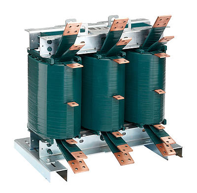
A starting transformer is a vital component for motor-driven applications, particularly in industrial and commercial sectors. Its primary role is to reduce the initial inrush current during motor startup, ensuring smoother operations and enhanced equipment longevity. Starting transformers are specially designed to handle high transient currents while protecting electrical systems from voltage spikes that could otherwise lead to operational disruptions or equipment damage.

These transformers are typically used with large motors, where the initial surge of current can be several times higher than the normal running current. By reducing this surge, the starting transformer prevents overloading the power supply and mitigates the risk of damaging sensitive electrical components.
Trusted by world-class brands & organizations of all sizes

Technical Parameters

Starting Transformer Technical Parameters

Voltage Ratio: 11kV/380V, 6.3kV/380V, 3.3kV/380V (Customized according to customer needs)

Frequency: 50Hz/60Hz

Cooling Type: ONAN (Oil Natural Air Natural)

Primary Winding Impedance: Typically 5-10%

Secondary Voltage: 380V (standard); can be customized for different applications

Short-Circuit Impedance: Designed for low impedance to limit inrush current.

Start Duration: Typically 5-10 seconds (for gradual voltage ramp-up)

Contact us to upgrade or install your energy system.

Product Feature

Our starting transformer ensures smooth and reliable motor startups in industrial and commercial settings. Designed for high inrush currents, it minimizes power fluctuations and optimizes energy efficiency. Secure your operation’s stability today!

These transformers are typically used with large motors, where the initial surge of current can be several times higher than the normal running current. By reducing this surge, the starting transformer prevents overloading the power supply and mitigates the risk of damaging sensitive electrical components.

Applications include industrial machinery, HVAC systems, pumps, compressors, and other large motor-driven equipment, where reliable and efficient startup is critical. They come in a variety of configurations, including autotransformers and isolated types, depending on the specific needs of the electrical system.

Key Advantages:

  • Efficient Motor Startup: Minimizes high inrush currents that could lead to motor or transformer damage.
  • Enhanced Energy Efficiency: Reduces power losses associated with motor starting.
  • Operational Reliability: Protects the electrical infrastructure and equipment, ensuring continuous, reliable operation.
  • Flexibility: Available in various sizes and configurations to suit different motor ratings and application needs.

By choosing a quality starting transformer, you ensure the smooth and efficient operation of your systems while reducing operational risks. Whether you are upgrading your facilities or designing a new system, our starting transformers provide unmatched reliability and performance.

Applications:

Suitable for large motors, pumps, compressors, and other industrial machinery requiring controlled startup.

Large Industrial Motors:

Used to limit starting current in motors driving heavy equipment like compressors, large fans, and pumps.

Power Stations:

Often employed in power plants to start large generator motors or other significant electrical equipment.

Oil & Gas:

Essential for starting large pumps and compressors used in oil and gas facilities.

QC & Guarantee

Market Orientation and Service Commitment

In response to fierce market competition and to meet customer demands, our company adheres to a market-oriented approach and a customer-centric philosophy. We have earned widespread recognition from our clients through efficient, comprehensive services and superior product quality.

Our Commitments

  1. Product Lifespan Guarantee: The operational lifespan of our transformers is no less than 30 years.
  2. Strict Quality Control:
    • Upon receiving bid documents, we promptly initiate the evaluation process to ensure all customer requirements are fully addressed.
    • We carefully select certified suppliers and strictly follow quality management standards to control and inspect raw materials and components.
    • We produce high-quality, customer-satisfactory parts in full compliance with contract and technical agreement requirements.
  3. After-Sales Service Commitment:
    • All performance indicators and technical specifications of our transformers meet or exceed national standards.
    • Within 3 years of installation and commissioning, if any oil leakage occurs due to manufacturing defects in oil-immersed transformers, we will repair it at no cost.
    • For any critical component defects identified during production or issues discovered during installation, we prioritize resolution to meet project timelines, followed by thorough responsibility analysis and necessary repairs or replacements.
    • We welcome customers to supervise the manufacturing process at our facility and will provide full support.

After-Sales Support

We offer comprehensive after-sales services, including free guidance for installation and commissioning. After the product is operational, if the customer requires support, our service team will respond promptly:

  • Arrival on-site within 24 hours for locations within 300 km.
  • Arrival on-site within 48 hours for locations beyond 300 km.

Additionally, we have established a robust regular follow-up system. We conduct periodic written or on-site visits to monitor the performance of in-service products, ensuring our customers have continuous peace of mind.

International Service Methods

Remote Technical Assistance

Our service team provides 24/7 online technical support, including video calls, troubleshooting guides, and documentation, ensuring immediate assistance regardless of time zones.
Detailed remote diagnostics can be conducted using customer-provided data or live visual inspections.

On-Site Support

For complex issues, we dispatch experienced technicians to the customer site promptly, adhering to the agreed international response timelines.
On-site services include installation guidance, commissioning, maintenance, and repairs.

Dedicated Service Representatives

Each international client is assigned a dedicated service representative to coordinate all aspects of after-sales support, including issue resolution and regular follow-ups.

Local Service Partnerships

We collaborate with certified local service partners in key markets to ensure faster response times and efficient support. These partners are fully trained in our products and processes to uphold our quality standards.
Regular Follow-Up Visits

Post-installation, we perform scheduled follow-up visits, either in person or virtually, to monitor product performance and address customer feedback. This proactive approach ensures optimal operation and customer satisfaction.

Why This Matters

Our comprehensive international service system combines swift response, advanced technical support, and localized expertise to provide our global clients with reliable and professional after-sales services. We are committed to building lasting partnerships through consistent support and excellence.

FAQs

Starting transformers FAQs

When purchasing an Starting Transformer, you may want to know the following questions & answers.

The voltage rating of a starting autotransformer is typically designed to match the line voltage (the supply voltage) and the motor’s voltage. The transformer reduces the voltage to a specific level to facilitate safe and smooth motor startup, depending on the desired reduction factor.

General Voltage Ratings for Starting Autotransformers:

  1. Low-Voltage Autotransformer Starters:

    • Typical voltage range: 230 V to 690 V (commonly 380 V, 415 V, 440 V, or 480 V for industrial systems).
    • Common applications: Used for motors in smaller or medium-sized equipment (pumps, fans, compressors) in manufacturing, HVAC, and other industrial sectors.
  2. Medium-Voltage Autotransformer Starters:

    • Typical voltage range: 3.3 kV to 13.8 kV (can extend higher depending on industrial needs).
    • Common applications: Used for motors in heavy-duty machinery such as large pumps, crushers, and mills in industries like mining, power plants, and oil & gas.
  3. High-Voltage Autotransformer Starters:

    • Typical voltage range: 15 kV and above (up to 35 kV or more for very large motors).
    • Common applications: These are used for large motors in critical industries, where high-voltage motors are necessary for large industrial or commercial operations.

Key Considerations for Voltage Rating:

  1. Primary and Secondary Voltage:

    • The primary voltage (the voltage supplied to the autotransformer) should match the incoming line voltage (such as 400 V, 480 V, or 600 V for typical industrial systems).
    • The secondary voltage (the voltage output to the motor) is lower, typically reduced to 50%, 60%, or 80% of the primary voltage, depending on the autotransformer configuration and the application.
  2. Voltage Reduction Ratio:

    • The voltage reduction ratio is a critical factor in autotransformer starters. A typical reduction is:
      • 50% reduction in voltage means the autotransformer will deliver 50% of the full line voltage to the motor during startup.
      • For example, for a 400 V line, a 50% voltage reduction would mean the motor receives 200 V during startup.
    • This reduction reduces the starting current, thus reducing the stress on both the motor and the electrical system during startup.
  3. Motor Voltage Matching:

    • The autotransformer is sized to match the motor’s rated voltage. This ensures that the motor receives the correct voltage after the autotransformer reduces the input voltage.
    • If the motor is designed for 400 V, and the line voltage is 480 V, the autotransformer would step down the voltage to 50% (240 V), matching the motor’s characteristics.

Summary:

  • Voltage Rating for Starting Autotransformers:
    • Low-voltage systems: 230 V to 690 V.
    • Medium-voltage systems: 3.3 kV to 13.8 kV.
    • High-voltage systems: 15 kV and above.
  • The voltage rating must correspond to both the line supply voltage and the motor’s rated voltage while achieving the necessary voltage reduction for safe motor starting.

The power ratings for starting transformers (often used in autotransformer starter applications) are generally specified in kVA (kilovolt-amperes) or MVA (megavolt-amperes). The power rating depends on the motor’s size and the characteristics of the electrical system.

Here is a breakdown of the available power ratings for starting transformers:

1. Small Power Ratings (up to 100 kVA)

  • Common Range: 5 kVA – 100 kVA
  • Applications: Used for small motors (typically up to 50-75 HP or around 37-55 kW), such as in smaller pumps, HVAC systems, and small conveyors.

2. Medium Power Ratings (100 kVA – 500 kVA)

  • Common Range: 100 kVA – 500 kVA
  • Applications: Suitable for medium-sized motors (typically 75 HP to 500 HP or 55 kW to 375 kW), found in industries such as manufacturing, medium-sized pumps, compressors, and industrial conveyors.

3. Large Power Ratings (500 kVA – 2500 kVA and above)

  • Common Range: 500 kVA – 2500 kVA
  • Applications: Required for large motors (typically 500 HP to 2500 HP or 375 kW to 1.85 MW) used in heavy industries like cement, steel mills, large pumps, crushers, and mining equipment.

4. Very Large Power Ratings (2500 kVA and above)

  • Common Range: 2500 kVA to 10000 kVA (10 MVA)
  • Applications: For extremely large motors (typically over 2500 HP or 1.85 MW), such as those used in power plants, large-scale mining operations, large compressors, and other critical industrial machinery.

Key Considerations for Starting Transformer Power Ratings:

  1. Motor Power and Starting Current:

    • The starting transformer is selected based on the motor’s full-load current and the desired starting characteristics. The power rating of the transformer needs to be high enough to handle the initial surge of current during motor startup, which can be 6-8 times the full-load current.
    • For an autotransformer starting method, the transformer typically has a power rating 1.5 to 2.5 times the motor’s full-load power rating, since autotransformers reduce the voltage supplied to the motor, but the starting current remains significantly high.
  2. Voltage Rating:

    • The starting transformer should match the line voltage and provide the correct secondary voltage to reduce the motor’s starting voltage by a desired factor (e.g., 50%, 60%, or 80% of rated voltage). The transformer size should be adequate to handle these voltage drops during startup.
  3. Power Factor:

    • The transformer’s power rating should also take into account the power factor of the motor. During motor starting, the transformer must supply reactive power to the motor in addition to the real power, so power factor correction might be needed depending on the application.

Example Calculations:

  • For a motor rated at 1000 HP (approximately 750 kW):

    • The starting transformer would typically have a rating of 1.5 to 2 times the motor power:
      • Transformer rating could be between 1500 kVA and 2000 kVA.
  • For a 2500 HP (approximately 1800 kW) motor:

    • The starting transformer might have a rating between 3750 kVA to 5000 kVA.
  • For very large motors (e.g., 5000 HP or higher):

    • Transformer ratings can exceed 10 MVA (10,000 kVA), depending on the exact requirements of the application.

Summary:

  • Power Ratings for starting transformers typically range from 5 kVA for small motors to 10,000 kVA (10 MVA) for very large motors.
  • For industrial applications, the transformer power rating is typically 1.5 to 2.5 times the motor’s power rating, depending on the motor size and the starting current requirements.

The rated current of a starting transformer is the amount of current that the transformer can handle safely at its rated voltage under normal operating conditions. The current rating is critical because it dictates the transformer’s ability to supply the required power to the motor during startup, especially when using techniques like the autotransformer method.

How to Calculate the Rated Current for the Starting Transformer

To calculate the rated current of a starting transformer, we use the formula:

Irated=Srated3×VprimaryI_{rated} = \frac{S_{rated}}{\sqrt{3} \times V_{primary}}

Where:

  • IratedI_{rated} is the rated current in amperes (A),
  • SratedS_{rated} is the transformer’s power rating in kVA (kilovolt-amperes),
  • VprimaryV_{primary} is the primary voltage of the transformer in volts (V),
  • 3\sqrt{3} accounts for the three-phase AC power system (assuming a three-phase transformer).

Key Factors to Consider

  1. Primary Voltage:

    • The rated current depends on the primary voltage of the transformer, which is the supply voltage. Typical primary voltages are 400V, 480V, 600V, 6.6 kV, 11 kV, and so on.
  2. Power Rating (kVA or MVA):

    • The kVA rating of the transformer determines how much power it can supply. The rated current is directly proportional to the kVA rating.
  3. Secondary Voltage and Autotransformer Configuration:

    • For an autotransformer, the secondary voltage (voltage delivered to the motor) is reduced based on the starting voltage (e.g., 50%, 60%, or 80%). However, the primary current is based on the total kVA rating, and not the voltage reduction factor, because the transformer is designed to supply the power for starting.

    • For instance, with a 50% voltage reduction in the autotransformer, the current to the motor will be reduced, but the starting transformer will still handle the full current based on the motor’s full power demand.

Example 1: Low-Voltage Transformer (400V, 1000 kVA)

Let’s say we have a starting transformer rated at 1000 kVA with a primary voltage of 400V (a common low-voltage industrial system).

Irated=1000 kVA3×400 VI_{rated} = \frac{1000 \, \text{kVA}}{\sqrt{3} \times 400 \, \text{V}} Irated=1000×10001.732×400I_{rated} = \frac{1000 \times 1000}{1.732 \times 400} Irated=1,000,000692.8=1443.4 AI_{rated} = \frac{1,000,000}{692.8} = 1443.4 \, \text{A}

So, the rated current for this 1000 kVA transformer is approximately 1443 A at 400V.

Example 2: Medium-Voltage Transformer (6.6 kV, 2500 kVA)

For a 2500 kVA starting transformer with a 6.6 kV primary voltage:

Irated=2500 kVA3×6600 VI_{rated} = \frac{2500 \, \text{kVA}}{\sqrt{3} \times 6600 \, \text{V}} Irated=2500×10001.732×6600I_{rated} = \frac{2500 \times 1000}{1.732 \times 6600} Irated=2,500,00011,419.2=219.2 AI_{rated} = \frac{2,500,000}{11,419.2} = 219.2 \, \text{A}

The rated current for this 2500 kVA transformer is approximately 219 A at 6600V.

Key Considerations for the Rated Current:

  • Motor Starting Current: The transformer must be capable of handling the inrush current during motor startup, which is typically 6-8 times the motor’s full-load current. However, since starting transformers are designed to reduce the voltage during the motor’s startup, the actual current delivered to the motor will be much lower than the full load current.

  • Autotransformer Effect: In the case of an autotransformer, the starting transformer’s current rating is not reduced by the voltage reduction. The starting transformer must still supply power at the full kVA rating, even though the voltage supplied to the motor is reduced.

  • Transformer Sizing: The current rating of the transformer is directly linked to the total amount of power it must supply. It is important to properly size the transformer to handle both the steady-state load and the inrush current during motor startup.


Summary:

  • The rated current of a starting transformer is calculated based on its power rating (kVA) and primary voltage.
  • It is given by: Irated=Srated3×VprimaryI_{rated} = \frac{S_{rated}}{\sqrt{3} \times V_{primary}}
  • The rated current typically ranges from a few hundred amperes (for smaller transformers in low-voltage systems) to several thousand amperes (for large transformers in medium-voltage and high-voltage systems).

The core material used in starting transformers is a critical component for their performance, as it affects the transformer’s efficiency, cost, and ability to handle high inrush currents during motor startup. The core material is primarily chosen for its magnetic properties—specifically, its ability to handle the alternating current (AC) flux with minimal losses.

Common Core Materials for Starting Transformers:

1. Silicon Steel (Electrical Steel)

  • Type: Grain-Oriented Electrical Steel (GOES) or Non-Grain-Oriented Electrical Steel (NGOES)

  • Description: Silicon steel is the most common core material for transformers, including starting transformers. Silicon is added to steel to enhance its magnetic permeability, reduce core losses, and increase efficiency in the AC frequency range. Silicon steel provides good magnetic flux density and low hysteresis loss, making it highly effective for handling the fluctuating magnetic fields in transformers.

  • Key Features:

    • High Magnetic Permeability: Allows for efficient energy transfer.
    • Low Core Loss: Minimizes heat generation, which is essential during motor startup when the transformer handles high inrush currents.
    • Good Saturation Characteristics: Silicon steel is highly resistant to saturation, which is crucial during the high inrush current when starting motors.
    • Availability: Widely used and cost-effective for a wide range of transformer ratings.
  • Usage:

    • Grain-Oriented Silicon Steel (GOES) is used in high-efficiency transformers because it allows magnetic flux to flow easily in one direction, reducing core loss and increasing the transformer’s efficiency.
    • Non-Grain-Oriented Silicon Steel (NGOES) is used for applications where multi-directional flux is prevalent (e.g., in three-phase systems), and cost is more of a consideration than absolute efficiency.

2. Amorphous Steel (Amorphous Metal)

  • Type: Amorphous Steel (Non-Crystalline Steel)

  • Description: Amorphous steel, also known as metallic glass, is a newer core material that is gaining attention in transformer design due to its ultra-low core losses. It has a random atomic structure, unlike crystalline materials like silicon steel. This structure leads to extremely low hysteresis loss, making it a highly efficient core material for transformers.

  • Key Features:

    • Very Low Core Loss: Significantly reduces energy loss compared to silicon steel, even at high frequencies.
    • High Efficiency: Particularly beneficial in applications where energy efficiency is crucial, such as for transformers operating at higher load factors or in systems with frequent startup operations.
    • Higher Cost: The production of amorphous steel is more expensive than traditional silicon steel, though it is more efficient.
  • Usage:

    • Amorphous steel is increasingly being used in transformers designed for low losses and high efficiency, but it may not be as common in standard industrial starting transformers due to its higher cost.

3. Ferrite Cores (for Specific Applications)

  • Type: Ferrite

  • Description: Ferrite cores are primarily used in high-frequency transformers (e.g., in electronics, radio frequency applications), rather than in traditional industrial power transformers. Ferrites are ceramics made from iron oxide and other metals and have high resistance to eddy currents, which makes them ideal for high-frequency applications.

  • Key Features:

    • High Resistance to Eddy Currents: Useful at higher frequencies.
    • Used Mainly in High-Frequency Circuits: Not common in low-frequency transformers like those used for motor starting, where silicon steel is more efficient.
  • Usage:

    • Ferrite cores are not typically used in industrial starting transformers for motors, but may be found in smaller, specialized transformers (e.g., in switching power supplies or electronic applications).

Factors Influencing Core Material Selection for Starting Transformers:

  1. Efficiency and Core Loss:

    • The core material should minimize core loss (hysteresis and eddy currents), which is critical when the transformer is frequently subjected to high inrush currents during motor startups. Silicon steel (especially grain-oriented) is highly effective at minimizing core losses in low-frequency applications like motor starters.
  2. Magnetic Saturation:

    • The material needs to have good saturation characteristics so that it can handle the large inrush currents without saturating and causing inefficiencies or overheating. Silicon steel has a high saturation flux density, which makes it suitable for transformers that experience large transient currents.
  3. Thermal Stability:

    • The core material must be able to withstand the heat generated during the motor startup process. The temperature rise during inrush currents should be minimized, and silicon steel’s low core losses help with heat management.
  4. Cost-Effectiveness:

    • Silicon steel is the most cost-effective solution for most applications. Amorphous steel, while more efficient, tends to be more expensive, making it less common for standard motor starting transformers unless energy savings are a high priority.

Summary of Core Materials Used in Starting Transformers:

  • Primary Core Material: Silicon Steel (Electrical Steel)

    • Grain-Oriented Electrical Steel (GOES): Used for high-efficiency transformers.
    • Non-Grain-Oriented Electrical Steel (NGOES): Used for general-purpose transformers.
  • Secondary Core Material: Amorphous Steel (for ultra-low core losses but higher cost).

  • Rarely Used in Power Transformers: Ferrite Cores (mainly for high-frequency applications, not typical for motor starting transformers).

Conclusion:

The most commonly used core material for starting transformers is silicon steel, particularly grain-oriented electrical steel (GOES), due to its high efficiency, low core losses, and cost-effectiveness. Amorphous steel is an alternative for high-efficiency applications but comes with a higher cost. Ferrite cores are not typically used in industrial starting transformers but might be used in high-frequency applications.

The maximum short-circuit withstand capacity of a starting transformer refers to the highest amount of short-circuit current the transformer can handle without sustaining damage during a short-circuit event. This capacity is critical because, during a short-circuit, the transformer experiences a large and sudden surge in current, which could cause thermal damage to the windings and core if the transformer is not rated to withstand such high current levels.

The short-circuit withstand capacity is usually specified in terms of kA (kiloamperes) or MVA (megavolt-amperes) and is often given as the maximum fault current that the transformer can endure for a specific duration, typically in seconds. This is important for ensuring that the transformer can survive short-circuit events without failure and can be quickly disconnected from the system by protective devices.

Key Factors Affecting Short-Circuit Withstand Capacity:

  1. Transformer Size (Power Rating):

    • The larger the transformer, the higher the short-circuit withstand capacity, because larger transformers are designed to handle higher fault currents.
    • Short-circuit capacity is often expressed as a multiple of the transformer’s full-load current (in kA or MVA).
  2. Short-Circuit Duration:

    • The short-circuit withstand capacity is typically based on how long the transformer can handle the fault current. Common durations are:
      • 1 second
      • 3 seconds
      • 5 seconds
      • Longer durations may be required in some heavy-duty or critical applications.
    • The transformer is designed to handle the short-circuit current for the duration needed for protective equipment to isolate the fault, typically through fuses, circuit breakers, or relays.
  3. Impedance of the Transformer:

    • The impedance (often referred to as Z in ohms) of the transformer impacts the amount of fault current that will flow during a short-circuit. The lower the impedance, the higher the fault current.
    • Transformer impedance values are typically specified as percentage impedance (often between 4% to 6%) and can be used to estimate fault currents.
  4. Cooling Type:

    • Air-cooled transformers may have a lower short-circuit withstand capacity compared to oil-cooled or forced-oil cooled transformers, which can dissipate heat more efficiently during a short-circuit event.
  5. Construction and Standards:

    • The standards by which the transformer is built (such as IEC, ANSI, or IEEE) will influence its short-circuit withstand capacity. Transformers built to IEC 60076 or ANSI C57.12.00 standards are generally tested for their ability to withstand short circuits.

How to Estimate Short-Circuit Withstand Capacity:

The maximum short-circuit withstand capacity of a transformer is typically defined in terms of kA (kilamperes) or MVA (megavolt-amperes) for a specified duration, but the exact value will depend on the transformer’s rated power, impedance, and design parameters. To calculate the approximate short-circuit current, you can use the following formula:

Isc=VratedZtransformerI_{sc} = \frac{V_{rated}}{Z_{transformer}}

Where:

  • IscI_{sc} = short-circuit current in amperes (A),
  • VratedV_{rated} = rated voltage in volts (V),
  • ZtransformerZ_{transformer} = impedance of the transformer in ohms (Ω).

For example, for a 1000 kVA transformer with a 6.6 kV rated voltage and 5% impedance, the approximate short-circuit current would be calculated as follows:

  1. Transformer Base Current (Full-load Current):

    IFL=Srated3×Vrated=1000 kVA3×6600 V=87.1 AI_{FL} = \frac{S_{rated}}{\sqrt{3} \times V_{rated}} = \frac{1000 \, \text{kVA}}{\sqrt{3} \times 6600 \, \text{V}} = 87.1 \, \text{A}
  2. Short-Circuit Current (with 5% impedance):

    Isc=VratedZtransformer=6600 V0.05×6600 V=20 kAI_{sc} = \frac{V_{rated}}{Z_{transformer}} = \frac{6600 \, \text{V}}{0.05 \times 6600 \, \text{V}} = 20 \, \text{kA}

Thus, the short-circuit withstand capacity of this transformer would be approximately 20 kA for a fault duration of 1 second (or whatever duration is specified by the manufacturer).

Typical Short-Circuit Withstand Capacities for Starting Transformers:

  • Small Transformers (up to 500 kVA):

    • Short-Circuit Withstand Capacity: Typically 6 kA to 20 kA for 1-second fault duration.
  • Medium Transformers (500 kVA to 2500 kVA):

    • Short-Circuit Withstand Capacity: Typically 10 kA to 30 kA for 1-second fault duration.
  • Large Transformers (2500 kVA and above):

    • Short-Circuit Withstand Capacity: Typically 20 kA to 40 kA (or higher) for 1-second fault duration, depending on the transformer design and the size of the motor it serves.

Industry Standards:

  • According to IEC 60076 (International Electrotechnical Commission standards) and ANSI C57.12.00 (American National Standards Institute), transformers are generally required to withstand short-circuit currents for a duration of 1 to 5 seconds. The actual withstand capacity depends on the specific type of transformer and the application requirements.

Summary:

  • The maximum short-circuit withstand capacity of a starting transformer varies based on its size, impedance, and construction, but it typically ranges from 6 kA for smaller transformers to 40 kA or higher for large industrial transformers.
  • The duration for which the transformer can withstand a short-circuit typically ranges from 1 second to 5 seconds, with most transformers designed for 1-second fault durations.

Ultimate Guide

Starting Transformer Ultimate Guide

Faster global delivery

lifespan > 30 years

Top10 Power equipment cop in CN
National-level technology center

Why Choose us ?

Built to last,
engineered to perform.

Taishan Transformer is a key national-level manufacturer specializing in transformers, recognized as a “Contract-Honoring and Promise-Keeping” enterprise, a high-tech enterprise, and a national-level enterprise technology center. It is recommended in the national directory for rural and urban power grid construction and renovation, as well as a recommended supplier of major electromechanical equipment for hydropower projects. Its products have been awarded the title of “National Quality Inspection Qualified Product – Quality Trustworthy Product” and “Nationally Recognized Product for Mechanical Industry Users.

Our Project

Our products not only dominate the domestic market but are also exported to more than 30 countries and regions, including Russia, Southeast Asia, Africa, and the Americas, serving industries such as power, municipal engineering, metallurgy, and petrochemicals.

Bangladesh
CRRC Corporation Limited
oil-immersed transformers
Australia
FSGT(HK) Limited
oil-immersed transformers
Vietnam
CMT Southern Metropolis
oil-immersed transformers
Zambia
ITEZHI TEZHI POWER
oil-immersed transformers
Poland
Electro- Alfa International SRL
oil-immersed transformers
russia
Irkutsk Power Grid Corp
oil-immersed transformers
Zimbabwe
Zimbabwe power company
oil-immersed transformers
Bolivia
SinoHydro Corporation
oil-immersed transformers

Get a Quote / Support for Your Project

  • Don’t worry, we hate spam too!