In order to meet the needs of railway electrification development demand for electrified railway traction transformer special service conditions, combined with our company 500kV power transformer technology advantage and improve production quality assurance system, using the electromagnetic field, temperature field, fluid leakage magnetic field, and other professional technical analysis software company perfect, successfully developed a single-phase auto traction transformer 110kV single-phase traction substation, railway traction transformer, three-phase VV connected balance traction transformer and 220kV single-phase traction transformer, three-phase VX connected traction transformer. This series of products have the characteristics of short circuit capacity, over load capacity, low noise, low temperature rise and high reliability.
Trusted by world-class brands & organizations of all sizes










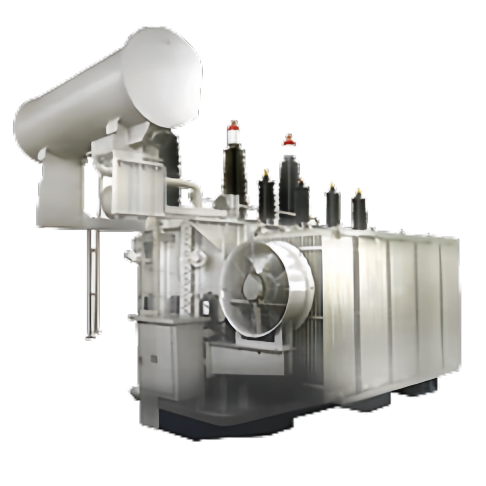
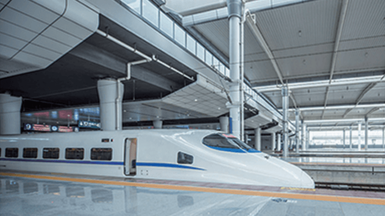
Railway traction autotransformer is applied to the electrified railway AT power supply mode, and has good anti-interference performance. It can eliminate or weaken the interference caused by the electrical interference source.
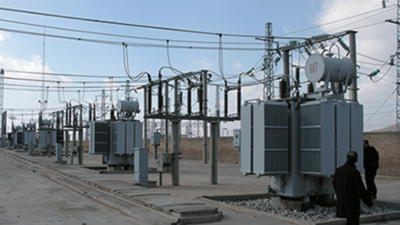
The magnitude of short circuit impedance is an important index to measure the performance of single-phase autotransformer.
In the calculation of short-circuit impedance, our company can control the short-circuit impedance to the lowest level by using electromagnetic simulation software. Converted to the low voltage side, the short-circuit reactance meets <0.45Ω.
The transformer is a low impedance transformer, and its short-circuit current and short-circuit mechanical force increase remarkably compared with the common transformer.
In order to ensure that the transformer has enough anti short circuit capability, our company developed the autotransformer traction transformer with short circuit resistance of mature technology, from design, process has taken corresponding measures, greatly improving the product and short circuit ability.
According to the load curve compiled over load capacity temperature analysis software customers and electrified railway standards, strictly abide by the relevant provisions, calculated according to the corresponding calculation method, which can meet the load curve of temperature rise, and have a certain degree of safety.

Technical parameter list of railway auto-transformer
| Type | Rated Capacity (kVA) | Rated Voltage (kV) | Connection Group | Rated Frequency (Hz) | No-load Loss (kW) | No-load Current (%) | Low Side Leakage Reactance (Ω) | Cooling Method | Weight (t) | Overall Dimension (mm) |
|---|---|---|---|---|---|---|---|---|---|---|
| OD-QY-20000/2×27.5 | 20000 | 2×27.5/27.5 | Ia0 | 50 | 8.5 | 0.35 | <0.45 | ONAN | Total: 20.5 | L: 3450 W: 3700 H: 4300 |
| OD-QY-25000/2×27.5 | 25000 | 2×27.5/27.5 | Ia0 | 50 | 10 | 0.35 | <0.45 | ONAN | Total: 23.5 | L: 3600 W: 3750 H: 4300 |
| OD-QY-31500/2×27.5 | 31500 | 2×27.5/27.5 | Ia0 | 50 | 12 | 0.4 | <0.45 | ONAN | Total: 26 | L: 3700 W: 3800 H: 4200 |
| OD-QY-40000/2×27.5 | 40000 | 2×27.5/27.5 | Ia0 | 50 | 14 | 0.35 | <0.45 | ONAN | Total: 29 | L: 3800 W: 4200 H: 4300 |
| OD-QY-50000/2×27.5 | 50000 | 2×27.5/27.5 | Ia0 | 50 | 17 | 0.25 | <0.2 | ONAN | Total: 33 | L: 4000 W: 4700 H: 4400 |
| OD-QY-63000/2×27.5 | 63000 | 2×27.5/27.5 | Ia0 | 50 | 20 | 0.2 | <0.2 | ONAN | Total: 37.5 | L: 4100 W: 4800 H: 4550 |
Note:
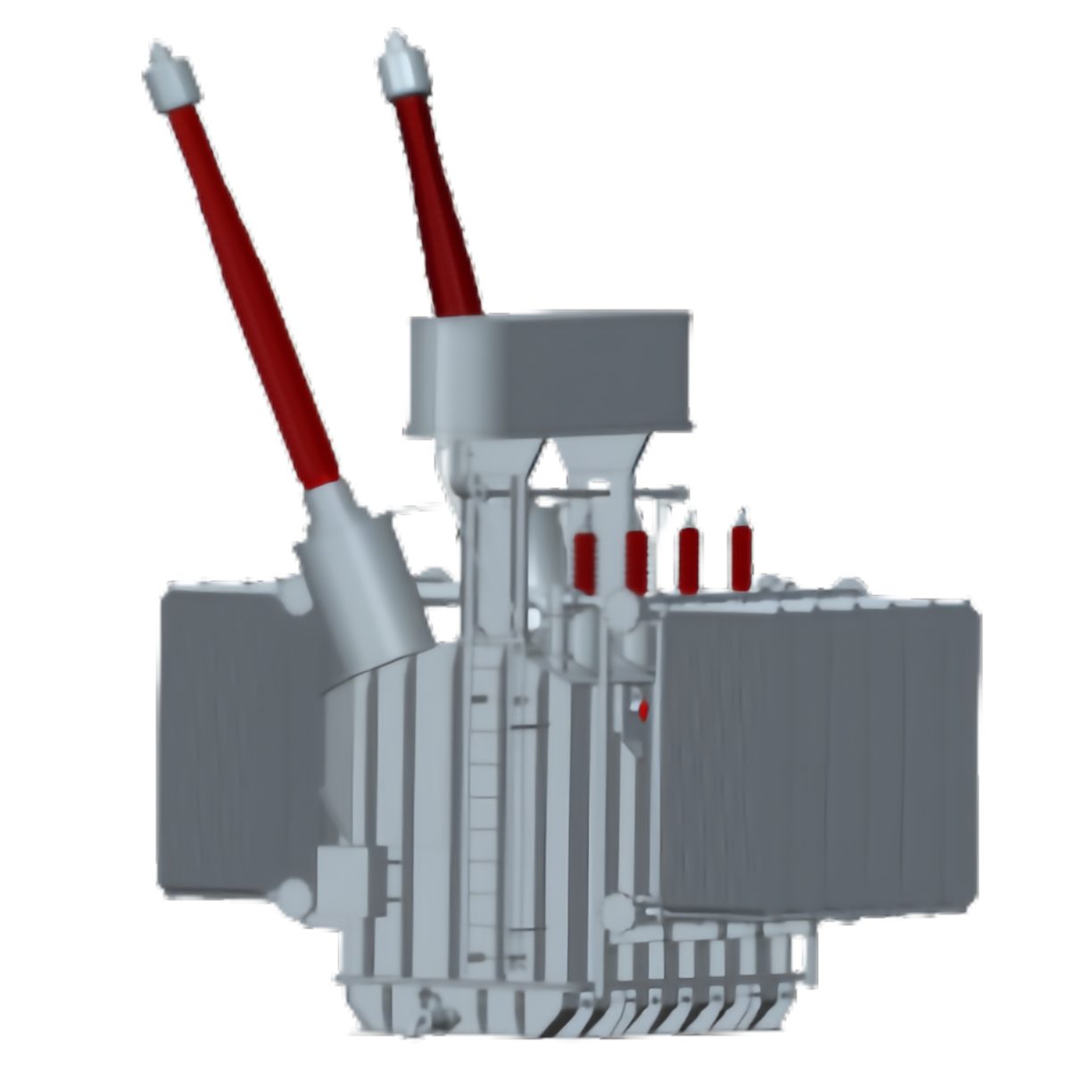
VX railway traction transformer is developed in recent years, a new type of railway traction transformer to adapt to the development of China high-speed railway, which is used for AT power supply mode, relative to other transformer AT power supply mode has obvious advantages, the capacity utilization rate is high, the level of high voltage power supply arm; compared with the pure single-phase traction transformer, can make the negative in order to reduce by half the effect. It has a wide application prospect.
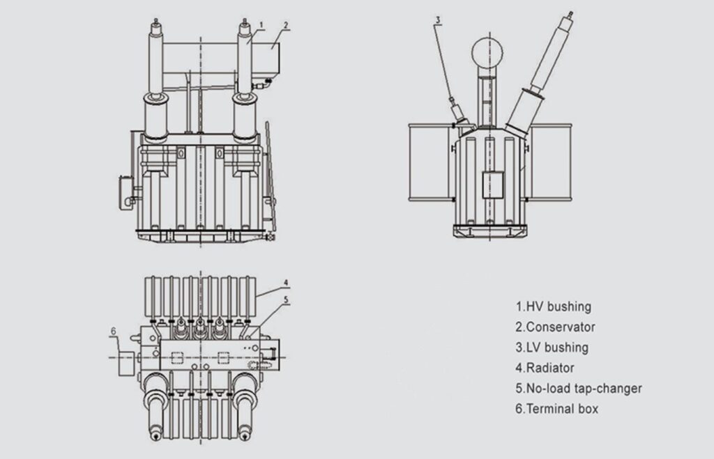
Two low voltage secondary winding capacity of flexible configuration, we can design different capacity according to the requirements of different lines; The structure can use two independent single-phase traction transformer, three-phase VX connected traction transformer split by external, and can also use the two single-phase transformers in the same tank in the three-phase VX form traction transformer.
Strong power supply capacity, long distance power supply, traction substation location convenient and less quantity of AT power supply, it can reduce the external power input, with excellent anti jamming effect, reducing the number of phase separation, conducive to the safe operation of the locomotive. The utility model is particularly suitable for the development of electrified high-speed railways in China, and has broad application prospects.
The transformer for low impedance transformer, compared with ordinary transformer, short-circuit current and short circuit mechanical force increases significantly. In order to ensure that the transformer has enough anti short circuit capability, our company developed the traction transformer with short circuit resistance of mature technology, and has taken corresponding measures from design, process, and greatly improves the product anti short circuit ability.
According to the load curve compiled over load capacity temperature analysis software of customers and electrified railway standards, we strictly abide by the relevant provisions, calculated according to the corresponding calculation method, which can meet the load curve of temperature rise, and have a certain degree of safety.
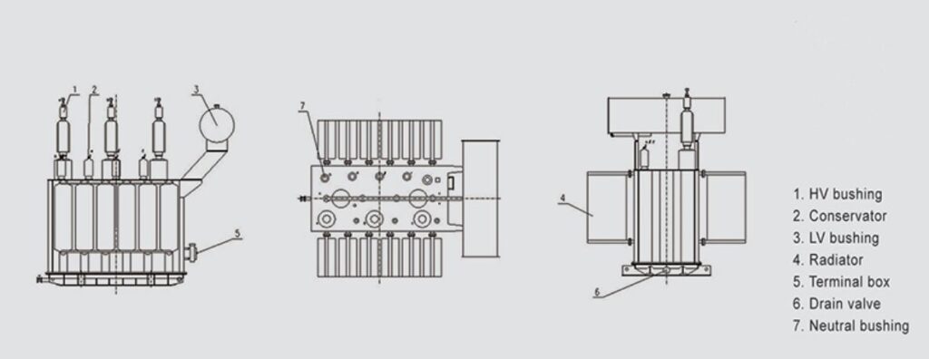
Composed of two single-phase transformer capacity of three-phase VV connection flexible collocation, can be the same or different, so the transformer capacity idle, the utilization rate of capacity can reach 100%, saving investment and operating costs.
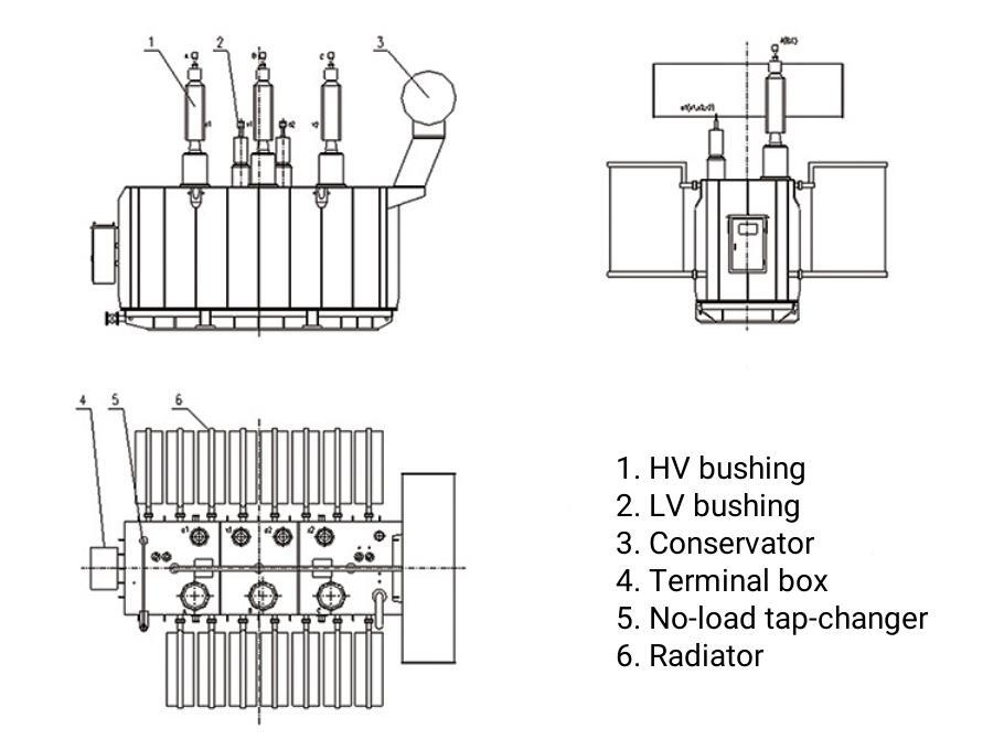
Technical parameter list of railway auto-transformer
| Type | Rated Capacity (kVA) | Rated Voltage (kV) | Connection Group | Rated Frequency (Hz) | No-load Loss (kW) | No-load Current (%) | Low Side Leakage Reactance (Ω) | Cooling Method | Weight (t) | Overall Dimension (mm) |
|---|---|---|---|---|---|---|---|---|---|---|
| OD-QY-20000/2×27.5 | 20000 | 2×27.5/27.5 | Ia0 | 50 | 8.5 | 0.35 | <0.45 | ONAN | Total: 20.5 | L: 3450 W: 3700 H: 4300 |
| OD-QY-25000/2×27.5 | 25000 | 2×27.5/27.5 | Ia0 | 50 | 10 | 0.35 | <0.45 | ONAN | Total: 23.5 | L: 3600 W: 3750 H: 4300 |
| OD-QY-31500/2×27.5 | 31500 | 2×27.5/27.5 | Ia0 | 50 | 12 | 0.4 | <0.45 | ONAN | Total: 26 | L: 3700 W: 3800 H: 4200 |
| OD-QY-40000/2×27.5 | 40000 | 2×27.5/27.5 | Ia0 | 50 | 14 | 0.35 | <0.45 | ONAN | Total: 29 | L: 3800 W: 4200 H: 4300 |
| OD-QY-50000/2×27.5 | 50000 | 2×27.5/27.5 | Ia0 | 50 | 17 | 0.25 | <0.2 | ONAN | Total: 33 | L: 4000 W: 4700 H: 4400 |
| OD-QY-63000/2×27.5 | 63000 | 2×27.5/27.5 | Ia0 | 50 | 20 | 0.2 | <0.2 | ONAN | Total: 37.5 | L: 4100 W: 4800 H: 4550 |
Note:
Please contact us for parameter information.
Please contact us for parameter information.
Please contact us for parameter information.
Contact us to upgrade or install your energy system.
In response to fierce market competition and to meet customer demands, our company adheres to a market-oriented approach and a customer-centric philosophy. We have earned widespread recognition from our clients through efficient, comprehensive services and superior product quality.
We offer comprehensive after-sales services, including free guidance for installation and commissioning. After the product is operational, if the customer requires support, our service team will respond promptly:
Additionally, we have established a robust regular follow-up system. We conduct periodic written or on-site visits to monitor the performance of in-service products, ensuring our customers have continuous peace of mind.
Remote Technical Assistance
Our service team provides 24/7 online technical support, including video calls, troubleshooting guides, and documentation, ensuring immediate assistance regardless of time zones.
Detailed remote diagnostics can be conducted using customer-provided data or live visual inspections.
On-Site Support
For complex issues, we dispatch experienced technicians to the customer site promptly, adhering to the agreed international response timelines.
On-site services include installation guidance, commissioning, maintenance, and repairs.
Dedicated Service Representatives
Each international client is assigned a dedicated service representative to coordinate all aspects of after-sales support, including issue resolution and regular follow-ups.
Local Service Partnerships
We collaborate with certified local service partners in key markets to ensure faster response times and efficient support. These partners are fully trained in our products and processes to uphold our quality standards.
Regular Follow-Up Visits
Post-installation, we perform scheduled follow-up visits, either in person or virtually, to monitor product performance and address customer feedback. This proactive approach ensures optimal operation and customer satisfaction.
Why This Matters
Our comprehensive international service system combines swift response, advanced technical support, and localized expertise to provide our global clients with reliable and professional after-sales services. We are committed to building lasting partnerships through consistent support and excellence.
When purchasing a Traction Transformer, you may want to know the following questions & answers.
A Traction Transformer is a vital component used in electric railways, metro systems, and high-speed trains, converting high-voltage electrical energy to a lower voltage suitable for traction motors and other electrical systems. The technical specifications of a traction transformer depend on various factors, including the type of system, rail voltage levels, and the specific design required for the application.
Here are the key technical specifications and voltage ratings you can expect for a traction transformer:
The primary voltage is the voltage supplied to the transformer from the power grid or overhead lines, typically ranging from:
The secondary voltage is the voltage output used for the traction motors and other electrical systems onboard trains or vehicles. Typical secondary voltages are:
The power rating is the maximum load that the traction transformer can handle. This is typically measured in MVA (Mega Volt-Amperes) or kVA (Kilo Volt-Amperes), with values varying based on the system’s needs:
The impedance of a traction transformer is generally in the range of 5-10% depending on the system design and the application, as this affects how the voltage is regulated under different load conditions. Traction transformers are designed to ensure stable voltage under high load demands, which are common in rail applications.
Traction transformers are generally cooled using oil or air:
Traction transformers are designed with high efficiency, often exceeding 98% to minimize energy loss, with both no-load losses and load losses being considered in their design.
In summary, traction transformers are designed to handle high electrical loads, provide stable power output to traction motors, and ensure the safety and reliability of the train’s electrical system. Voltage ratings and technical specifications can vary depending on the geographical area and the specific rail system’s requirements.
Yes, Traction Transformers are designed and built in compliance with various international standards to ensure safety, reliability, and interoperability across different rail systems and regions. Compliance with standards such as IEC, ANSI, and others is critical for ensuring that the transformers meet the electrical, mechanical, and safety requirements for rail applications. Here are the main standards and certifications that are commonly associated with traction transformers:
The IEC is the leading global organization for setting electrical and electronic standards. Traction transformers are typically designed to meet the following IEC standards:
IEC 60076: This is the primary standard for the design, testing, and operation of power transformers. Specific parts of this standard apply to traction transformers:
IEC 61378: This standard specifically applies to traction transformers used in electric railways and tram systems. It provides guidance on performance requirements, design, and testing of transformers for use in railway traction systems.
IEC 60947: Low-voltage switchgear and controlgear, which includes transformers in the scope for applications involving low-voltage components and protections used in railway electrification.
IEC 62271: High-voltage switchgear and controlgear standards, especially for transformers in high-voltage railway applications.
IEC 61810-1: Standards for electromechanical relays, applicable when relays are used in traction transformer protection systems.
The ANSI standards, used primarily in North America, are also applicable to traction transformers, especially for systems that adhere to American or Canadian railway systems. Relevant ANSI standards include:
ANSI C57 Series: These are the standards for transformers in North America, similar to IEC standards, focusing on the design, testing, and operational parameters.
ANSI C37.90: This standard relates to surge protection and electrical testing standards, critical for transformers used in areas with potential for electrical surges or faults.
ANSI/IEEE C57.109: Specific guidance on protection, including fault tolerance and load regulation, relevant for transformers used in heavy-duty applications like traction systems.
Depending on the region and application, traction transformers may also comply with various additional standards and certifications, such as:
IEEE Standards: These standards are used mainly in the United States but are influential globally. They focus on transformer design, testing, and materials.
UL Standards: In North America, transformers used in rail applications often comply with Underwriters Laboratories (UL) safety standards for electrical equipment.
EN Standards (European Norms): These standards are widely used across Europe:
ISO Certifications: Manufacturers often obtain ISO 9001 (Quality Management Systems) and ISO 14001 (Environmental Management) certifications to ensure that their transformers are manufactured according to high-quality standards and sustainable practices.
Traction transformers are indeed compliant with a wide range of international standards, including IEC, ANSI, and ISO, among others. These standards ensure that the transformers are safe, reliable, efficient, and suitable for use in the demanding environments of rail systems worldwide. Compliance with these standards helps ensure that traction transformers can operate across various regions and meet specific national or regional regulatory requirements.
The efficiency and energy losses of a Traction Transformer are critical factors in determining the overall performance, energy consumption, and operational costs of electric railways, metros, and high-speed trains. Since traction transformers play a central role in converting electrical energy from the overhead lines or third rail to the required voltage levels for traction motors and onboard systems, their efficiency is paramount to minimize waste and improve system sustainability.
The efficiency of a Traction Transformer is typically high, as they are designed for maximum performance under constant high-load operation. The efficiency is primarily determined by the ratio of output power to input power. This ratio is influenced by various factors, including load conditions, transformer design, cooling system, and the type of materials used.
Energy losses in a traction transformer can be broadly categorized into two main types: core losses (no-load losses) and copper losses (load losses).
Core losses, also known as no-load losses, occur in the transformer’s magnetic core due to the continuous magnetization and demagnetization process in AC transformers. These losses are relatively constant and do not depend on the load, but rather on the voltage applied to the transformer.
Copper losses occur due to the resistance in the transformer windings when electric current flows through them. These losses are proportional to the square of the current, meaning they increase with higher load currents.
In addition to core and copper losses, traction transformers may experience other minor losses:
The total losses in a traction transformer depend on the load factor, i.e., how much of the transformer’s rated capacity is being utilized. These losses are typically tested at multiple load levels to establish performance:
At Full Load: Total losses (core + copper + stray) typically range from 1% to 2% of the transformer’s rated power.
At 75% Load: The total losses reduce due to the decrease in copper losses, though core losses remain constant. In this case, the total losses might be around 0.8% to 1.5% of the rated power.
At 50% Load: Further reduction in copper losses leads to a more favorable efficiency, but core losses still remain the same. Total losses can fall to 0.6% to 1.2%.
At Light Load or Idle: The copper losses are minimal, but core losses dominate. Total losses might range from 0.5% to 1%.
The energy losses over a year depend on the average load the transformer operates at, the total operating hours, and the efficiency. For example, if a 25 MVA transformer operates at an average load of 60% over a year (8,000 operating hours), and assuming total losses are about 1.5% of rated power:
This is the amount of energy lost as heat, which would need to be dissipated via the cooling system.
Modern traction transformers are designed to minimize losses through various techniques, such as:
Reducing energy losses and improving transformer efficiency helps lower operational costs, minimize environmental impact, and enhance the sustainability of rail transportation systems.
In traction transformers, cooling is a critical factor to ensure efficient operation and to prevent overheating during high-load conditions. The cooling system is designed to dissipate the heat generated by core losses (no-load losses) and copper losses (load losses). These transformers are subjected to varying loads, and efficient cooling is essential for maintaining optimal performance and reliability.
The cooling system used in traction transformers depends on the size, design, and application. Generally, the most common cooling methods for traction transformers are:
ONAF stands for Oil Natural, Air Forced. This is one of the most widely used cooling methods for large oil-immersed traction transformers.
Advantages:
Typical Use: Large traction transformers with power ratings ranging from 10 MVA to over 100 MVA often use the ONAF system, particularly in environments where high-efficiency cooling is required to handle large amounts of heat dissipation.
OFAF stands for Oil Forced, Air Forced. This system is similar to ONAF, but with a more active cooling approach for the oil circulation.
Advantages:
Typical Use: The OFAF system is often used in very large traction transformers (typically above 50 MVA) and in applications where the transformer must operate at higher temperatures and under more demanding conditions, such as high-speed trains and heavy freight locomotives.
ONAN stands for Oil Natural, Air Natural. This is the simplest cooling system where the transformer relies entirely on natural processes for cooling.
Advantages:
Typical Use: This system is most commonly used in smaller traction transformers (less than 10 MVA) or in applications where the heat generation is lower, and passive cooling is sufficient.
OFWF stands for Oil Forced, Water Forced. This system uses water to assist in cooling the oil in the transformer, rather than air.
Advantages:
Typical Use: This system is used in very large traction transformers, typically in situations where higher reliability and cooling capacity are required, and where cooling via air is insufficient, such as for high-speed trains, substations, or heavy-duty rail applications.
Some advanced traction transformers may use other specialized or hybrid cooling techniques, including:
| Cooling System | Type | Key Features | Typical Use |
|---|---|---|---|
| ONAF | Oil Natural, Air Forced | Natural oil circulation with forced air cooling. | Standard for medium to large traction transformers (10–100 MVA). |
| OFAF | Oil Forced, Air Forced | Active oil circulation with forced air cooling. | Large traction transformers (above 50 MVA) requiring higher cooling capacities. |
| ONAN | Oil Natural, Air Natural | Natural oil circulation with natural air cooling. | Smaller traction transformers or those with lower power requirements (up to 10 MVA). |
| OFWF | Oil Forced, Water Forced | Active oil circulation with water cooling. | Very large traction transformers, typically high-power (above 50 MVA). |
The cooling system of a traction transformer plays a key role in ensuring its efficiency, longevity, and reliability. The choice of cooling method (ONAF, OFAF, ONAN, or OFWF) depends on the transformer’s size, the operating conditions, and the cooling requirements. For most high-power traction transformers, ONAF and OFAF systems are the most common due to their efficiency in handling large amounts of heat, while ONAN is used for smaller transformers. OFWF cooling systems are typically reserved for high-performance applications where advanced cooling is needed to handle the highest thermal loads.
The expected lifespan of a traction transformer under normal operating conditions typically ranges between 30 to 40 years, though this can vary depending on several factors such as design, operating environment, and maintenance practices.
Quality of Design and Materials:
Load Conditions:
Operating Environment:
Cooling Efficiency:
Maintenance Practices:
Transformer Design Features:
Under Normal Operating Conditions: The typical lifespan of a traction transformer is 30 to 40 years. This assumes the transformer operates within its design parameters, with appropriate load, cooling, and maintenance.
Well-Maintained Transformers: With good maintenance practices and optimal operating conditions, traction transformers can sometimes exceed the typical lifespan, potentially reaching 45 to 50 years or more.
Heavy Load or Extreme Conditions: If the transformer operates at higher loads or in harsher environmental conditions (e.g., high temperature, corrosive environments), the lifespan could be closer to 30 years.
The expected lifespan of a traction transformer, when properly maintained and operating under normal conditions, is typically between 30 to 40 years. However, with careful design, regular maintenance, and optimal operating conditions, it is possible to extend this lifespan further, sometimes up to 50 years or more. Key factors influencing lifespan include quality of materials, cooling system performance, operating load, and environmental conditions. Regular inspections, oil testing, and monitoring systems play an essential role in achieving the full service life.
Traction transformers, like all electrical transformers, are equipped with various safety features to prevent overloading and short-circuiting, both of which can lead to catastrophic failures, equipment damage, and safety hazards. These safety mechanisms are designed to protect the transformer, maintain reliable operation, and ensure the safety of the overall system. Below are the main safety features typically incorporated in traction transformers:
Overloading occurs when the transformer is subjected to higher electrical loads than it is designed for, which can lead to overheating, insulation degradation, and potential failure. To prevent this, the following features are used:
Short-circuits (whether internal or external) can cause high fault currents that can quickly destroy the transformer windings, insulation, and other components. To protect against short-circuits, the following safety features are typically included:
Overcurrent protection mechanisms prevent the transformer from being exposed to excessive currents, whether due to a short circuit or overload. The following systems are employed to provide overcurrent protection:
Oil-filled transformers are susceptible to internal faults that could lead to a pressure rise, especially during faults like short circuits or overloading, which can generate excessive heat or gas. To protect the transformer from overpressure and possible explosions:
Traction transformers are equipped with multiple layers of protection to prevent overloading and short-circuiting, ensuring safe, reliable, and efficient operation. These protections include:
By combining these safety features, traction transformers can operate under challenging conditions, and any faults or overloads can be quickly identified and addressed, thereby minimizing damage and ensuring operational safety.
Yes, traction transformers can indeed be customized for specific rail or tram applications. Customization is often necessary to meet the unique requirements of different rail networks, operating environments, and performance criteria. When tailoring a traction transformer for specific applications, manufacturers take into account several factors, including the voltage ratings, power output, environmental conditions, regulatory requirements, and specific operational demands of the transit system.
Here are some key aspects of customization that can be made for rail and tram applications:
Example: For tram applications, transformers can be specifically designed to convert the local supply voltage (e.g., 600 V DC, 750 V DC) into usable traction voltage, whereas for high-speed trains, the transformer might handle 25 kV AC or 15 kV AC and adapt to variable frequency operations.
Traction transformers are highly customizable to meet the specific needs of different rail and tram applications. These customizations can include adjustments to voltage levels, power ratings, cooling methods, environmental considerations, and safety features to ensure the transformer operates efficiently and safely in its particular setting. Customization can also extend to the size, weight, and integration of transformers, especially for urban tram systems or high-speed rail systems that operate in diverse and challenging conditions.
By tailoring traction transformers to the specific needs of the rail or tram network, it is possible to ensure optimal performance, reliability, and safety across a wide range of applications.
The environmental and temperature operating limits for a traction transformer are critical for ensuring that the transformer operates reliably and efficiently under varying environmental conditions. These limits can vary depending on the design specifications, cooling systems, and the specific rail or tram application (e.g., urban transit, high-speed rail, or freight systems).
However, in general, traction transformers are designed to handle a broad range of operating conditions, and their environmental and temperature limits are specified to ensure they perform optimally throughout their lifespan while also withstanding harsh conditions.
These ranges can vary depending on the specific transformer design and the cooling methods used.
The exact temperature limits depend on the insulation class used (typically Class A, Class B, or Class F for traction transformers).
Fire Resistance: Transformers for rail and tram applications must often meet fire resistance standards, especially if they are located in tunnels, substations, or urban environments. Fire-resistant insulation materials and flame-retardant oils may be used to reduce fire risks. Additionally, automatic fire suppression systems might be incorporated in critical installations.
Explosion Protection: In areas with a risk of explosive gases (e.g., near industrial facilities), explosion-proof transformers may be required. These transformers are designed with features that prevent sparks or high heat from igniting any flammable substances in the vicinity.
These standards provide guidelines for environmental limits, testing procedures, and safety protocols to ensure transformers can perform reliably across various environmental conditions.
| Factor | Operating Limits |
|---|---|
| Ambient Temperature | -25°C to +55°C |
| Wind and Vibration | Designed for typical wind and vibration, special designs for high-impact environments |
| Altitude | Up to 2,000 meters (may require derating above 1,000 meters) |
| Humidity | 95% relative humidity (sealed against moisture ingress) |
| Temperature Rise | 50°C to 70°C above ambient for windings and oil |
| Oil Temperature | 65°C to 85°C (maximum up to 95°C during overload) |
| Corrosion and Pollution | Corrosion-resistant coatings for coastal and industrial environments |
| Dust and Pollution | Sealed enclosures or filters for dusty environments |
| Fire Resistance | Fire-resistant insulation and flame-retardant oil for critical applications |
In conclusion, traction transformers are designed to operate in a wide range of environmental conditions, from extremely low to high temperatures, and under varying humidity, altitude, and pollution levels. Proper customization and design ensure that the transformer can handle these conditions and continue to operate safely and efficiently over the long term.
Taishan Transformer is a key national-level manufacturer specializing in transformers, recognized as a “Contract-Honoring and Promise-Keeping” enterprise, a high-tech enterprise, and a national-level enterprise technology center. It is recommended in the national directory for rural and urban power grid construction and renovation, as well as a recommended supplier of major electromechanical equipment for hydropower projects. Its products have been awarded the title of “National Quality Inspection Qualified Product – Quality Trustworthy Product” and “Nationally Recognized Product for Mechanical Industry Users.
Our products not only dominate the domestic market but are also exported to more than 30 countries and regions, including Russia, Southeast Asia, Africa, and the Americas, serving industries such as power, municipal engineering, metallurgy, and petrochemicals.
We're here for you !
let's Talk about your Project!