Tap changers are essential components in power transformers, designed to regulate voltage and maintain power quality in electrical systems. By adjusting the transformer winding ratios, tap changers allow voltage control without interrupting the power supply. This document explores the purpose, types, and operational significance of tap changers in modern transformer applications.
What Does a Tap Changer Do in a Transformer?
Transformers must adapt to fluctuating voltage conditions caused by varying load demands, grid disturbances, and distance from power sources. Without compensation, these changes can cause under-voltage or over-voltage, damaging equipment or reducing performance. A transformer without voltage regulation capability must either be oversized or paired with external devices—both costly and inefficient. That's where tap changers come in: they allow voltage fine-tuning directly at the transformer, ensuring steady delivery to end users.
A tap changer adjusts the transformer's output voltage by changing the turns ratio of its windings. It does this by selecting different "taps" on the winding—connection points along the coil that represent varying numbers of turns—thereby regulating the output voltage to compensate for load or supply variations. There are two main types: off-load tap changers (OLTC), which require the transformer to be de-energized before adjustment, and on-load tap changers (OLTC), which allow automatic or remote adjustment during normal operation without interrupting power.
Tap changers are essential for grid reliability, voltage regulation, and system efficiency in both utility and industrial transformers.
Tap changers change the voltage by adjusting the number of winding turns in use.True
Each tap corresponds to a specific point on the coil, and switching between them alters the transformer's turns ratio.
On-load tap changers can be adjusted while the transformer is energized.True
OLTCs are designed to switch taps under load without disrupting the power supply using arc suppression techniques.
All transformers must have on-load tap changers.False
Many smaller distribution transformers use off-load tap changers or fixed-ratio windings, depending on their voltage regulation needs.
1. Understanding Tap Changer Operation
A transformer's voltage ratio is proportional to the number of turns in the primary and secondary windings:
$$
V_s = V_p \times \frac{N_s}{N_p}
$$
- Taps are points along the winding where conductors are brought out and connected to a switch.
- By selecting a tap with more or fewer turns in use, the effective ratio changes, allowing output voltage to be increased or decreased in steps (typically ±5% to ±20%).
2. Off-load vs. On-load Tap Changers (OLTCs)
| Feature | Off-load Tap Changer (NLTC) | On-load Tap Changer (OLTC) |
|---|---|---|
| Adjustment requires power off | ✔️ Yes | ❌ No |
| Suitable for | Distribution transformers | Transmission & HV transformers |
| Adjustment frequency | Infrequent (manual) | Continuous/automatic |
| Typical voltage range | ±5% to ±10% | ±10% to ±25% in 16–33 steps |
| Arc suppression | Not required | Essential (vacuum, resistor, reactor) |
| Control type | Manual/mechanical | Motorized, automatic, remote-controlled |
🔌 OLTCs use diverter switches, arcing contacts, and transition resistors/reactors to prevent short-circuits or voltage spikes during switching.
3. Tap Changer Placement and Design
Tap changers are usually installed on the high-voltage (HV) winding side, where:
- Current is lower, reducing stress on contacts
- Voltage steps are larger, offering better control
| Tap Location | Description |
|---|---|
| HV Winding | Most common, reduces component size and complexity |
| Midpoint/center of winding | Minimizes voltage stress across insulation |
| Series or phase-wound taps | Used in complex autotransformer designs |
🛠 Designs vary by transformer type, voltage class, and regulatory requirements.
4. Voltage Regulation Use Case Example
Transformer rated: 33 kV / 11 kV with ±10% OLTC (in 17 steps)
| Tap Position | Output Voltage |
|---|---|
| -8 | 9.9 kV |
| 0 (Nominal) | 11.0 kV |
| +8 | 12.1 kV |
This flexibility allows grid operators to:
- Compensate for line voltage drops during peak demand
- Maintain stable downstream voltage under variable loads
- Optimize transformer efficiency and loading
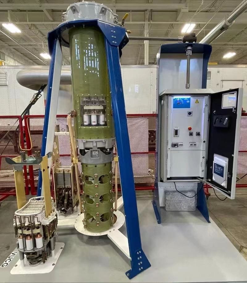
5. Tap Changer Construction Overview
| Component | Function |
|---|---|
| Selector Switch | Connects to desired tap on winding |
| Diverter Switch | Transfers load current without interruption |
| Transition Resistor/Reactor | Limits circulating current during tap change |
| Drive Mechanism | Electric motor or manual gear |
| Control System | Monitors voltage and automates tap selection |
| Oil Compartment (for OLTC) | Separate from main tank; includes oil for arc suppression and cooling |
🧪 Many modern OLTCs are enclosed in vacuum interrupters for maintenance-free operation and arc-free switching.
6. Automatic Voltage Regulation (AVR)
An AVR relay interfaces with the OLTC to:
- Monitor secondary voltage
- Compare with set reference
- Command tap changes when voltage deviates beyond threshold
- Operate with dead-band, time delay, and step logic
| AVR Feature | Function |
|---|---|
| Dead Band | Prevents unnecessary tap changes for minor fluctuations |
| Step Delay | Prevents rapid tap switching |
| Reverse Power Blocking | Disables tap changes during load reversal |
📡 OLTCs with AVRs are critical for smart grid integration, renewables, and voltage control loops.
7. Tap Changer Monitoring and Maintenance
| Aspect | OLTC | OLTC with Vacuum |
|---|---|---|
| Oil Condition | Needs regular testing | No oil (sealed unit) |
| Contact Wear | Regular inspection | Long-life contacts |
| Timing Mechanism | Should be calibrated | Electronic diagnostics available |
| Sensors | Oil temperature, position encoder, motor torque |
Modern tap changers may include:
- Condition monitoring sensors
- Digital tap position encoders
- Predictive maintenance analytics
8. Advantages and Limitations
| Advantage | Notes |
|---|---|
| Voltage Regulation | Maintains stable supply |
| Grid Flexibility | Supports varying load profiles |
| Energy Optimization | Reduces system losses |
| Automation-Ready | Integrates with SCADA, PLCs |
| Limitation | Notes |
|---|---|
| Complex Mechanism | Especially in OLTCs; needs precise control |
| Maintenance Needs | Diverter contacts and oil (unless vacuum-based) |
| Cost | Increases upfront investment in high-voltage applications |
What Are the Types of Tap Changers?
In voltage-regulated transformer systems, tap changers allow operators to fine-tune the turns ratio by switching to different winding taps. However, not all tap changers are created equal. Choosing the wrong type—manual instead of automated, or oil-based instead of vacuum-sealed—can lead to voltage instability, excessive maintenance, or even arcing faults under load. Therefore, it's critical to understand the different types of tap changers, their operating principles, and where each is best applied to maintain safe, efficient voltage regulation.
There are two main categories of transformer tap changers: Off-load Tap Changers (NLTC) and On-load Tap Changers (OLTC). Off-load types require the transformer to be de-energized for adjustment, making them suitable for fixed-ratio transformers or infrequent regulation. On-load tap changers operate while the transformer is energized and can adjust voltage under full load. Within OLTCs, further types exist based on transition technique: resistor-type, reactor-type, and vacuum-type. Each type has specific applications, maintenance profiles, and cost implications.
Choosing the correct tap changer ensures reliable voltage delivery, minimizes arc damage, and supports grid dynamics and automation.
Off-load tap changers require power to be disconnected before adjustment.True
NLTCs are mechanically simple and cannot safely switch current under load due to lack of arc suppression.
On-load tap changers can regulate voltage while the transformer is in service.True
OLTCs use diverter switches, resistors, or vacuum interrupters to safely make transitions under energized conditions.
All OLTCs use vacuum interrupters.False
While many modern OLTCs use vacuum technology, traditional models use oil-immersed resistors or reactors for arc suppression.
1. Off-Load Tap Changer (NLTC / De-energized Tap Changer)
| Feature | Description |
|---|---|
| Operation | Manual or motorized, only when transformer is offline |
| Use Case | Distribution transformers, cost-sensitive applications |
| Voltage Range | Typically ±5% or ±10%, 3–5 fixed steps |
| Mechanism | Simple rotary switch or tap links |
| Location | Usually on high-voltage winding side |
| Protection | No arc suppression needed |
Advantages:
- Economical
- Mechanically simple
- Maintenance-free
Limitations:
- Inflexible during live operations
- Not suitable for dynamic grid voltage control
2. On-Load Tap Changer (OLTC)
These operate under load conditions, allowing for voltage regulation without interrupting the power supply. Widely used in power transformers and HV substations.
a) Resistor-Type OLTC
| Mechanism | Two selector switches + diverter switch + resistors |
| Transition Type | Make-before-break via transition resistors |
| Arc Suppression | Resistors absorb arc energy |
| Application | Widely used in transmission transformers (≤245 kV) |
| Medium | Oil or vacuum insulated |
Advantages:
- Robust design
- Proven long-term performance
Drawbacks:
- Arcing can degrade oil over time
- Resistor heating limits switching frequency
b) Reactor-Type OLTC
| Mechanism | Uses a center-tapped reactor instead of resistors |
| Transition Type | Reactor limits circulating current between taps |
| Arc Suppression | Continuous current path avoids open contacts |
| Application | Older designs; rare in modern installations |
| Medium | Oil-immersed only |
Advantages:
- Low energy dissipation
- Longer switching life under moderate load
Drawbacks:
- Complex mechanics
- Requires larger compartment
- Less commonly used today
c) Vacuum-Type OLTC
| Mechanism | Vacuum interrupters in diverter switch |
| Transition Type | Arc quenched in vacuum (no oil contamination) |
| Arc Suppression | Clean and reliable |
| Application | Modern designs, especially in dry-type transformers or sensitive grids |
| Medium | Vacuum-sealed interrupters + dry compartment or oil (hybrid designs) |
Advantages:
- Virtually maintenance-free
- No oil degradation
- Clean, environmentally safer
- Compact
Limitations:
- Higher initial cost
- May require external diagnostics or drive systems
📌 Most modern OLTCs adopt vacuum switching technology to eliminate the need for oil maintenance.
3. Comparison Table: Tap Changer Types
| Type | Energized Switching | Arc Suppression | Insulation Medium | Maintenance Needs | Common Use |
|---|---|---|---|---|---|
| Off-load (NLTC) | ❌ No | Not required | Air/oil | Very low | Distribution transformers |
| Resistor OLTC | ✔️ Yes | Resistors | Oil | High (oil checks, contact wear) | Transmission, substations |
| Reactor OLTC | ✔️ Yes | Reactor | Oil | Moderate | Legacy HV systems |
| Vacuum OLTC | ✔️ Yes | Vacuum interrupters | Dry or hybrid | Very low | Modern power transformers, dry-type |
4. Selector and Diverter Functions in OLTCs
- Selector Switch: Connects to selected tap (no load carried)
- Diverter Switch: Makes/breaks load current, synchronized with arc suppression device (resistor/reactor/vacuum)
Transition must:
- Avoid open-circuiting the winding
- Avoid short-circuiting adjacent taps
- Limit arc duration and energy
These components are isolated in a separate tap changer compartment for safety and easier oil management.
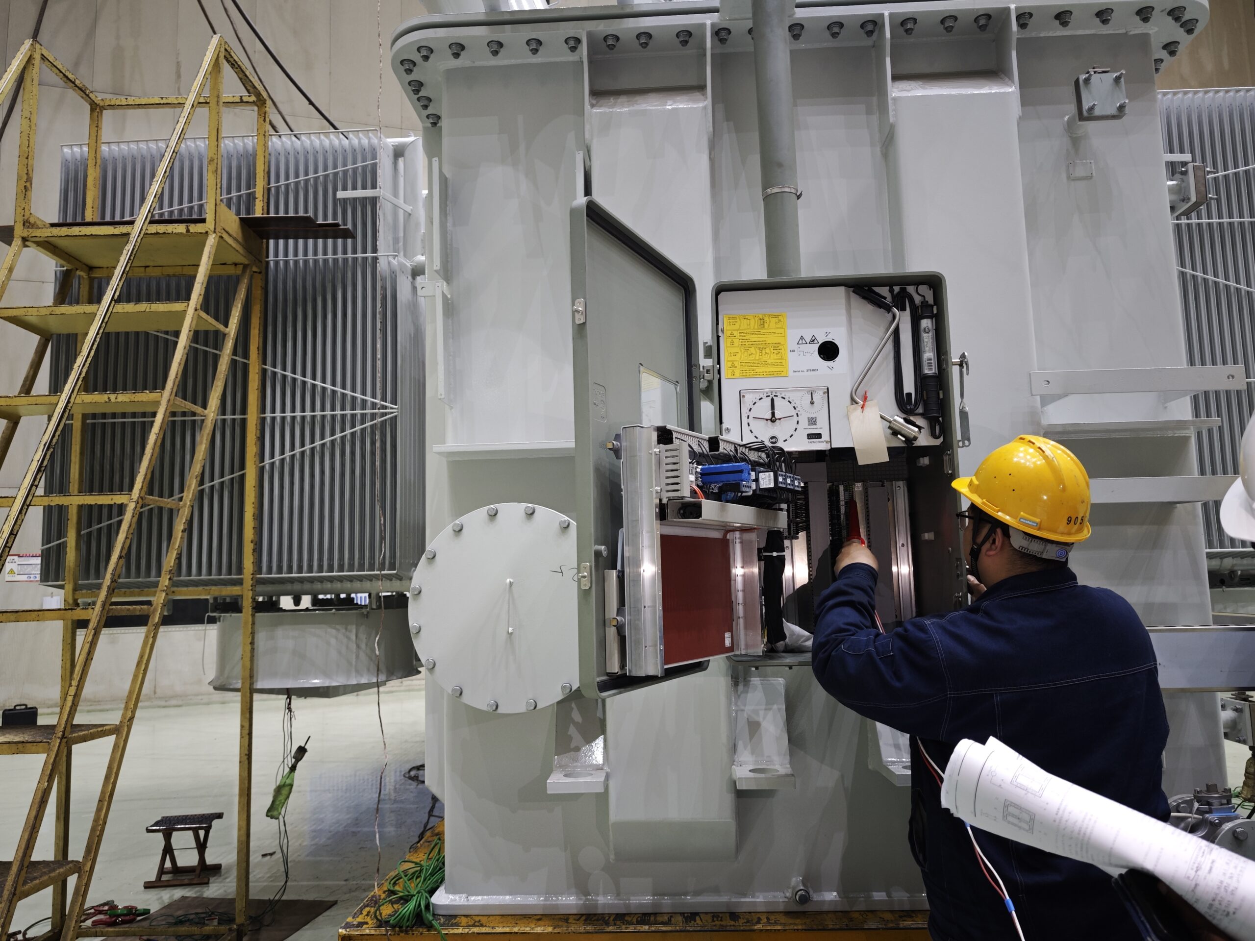
5. Digital and Motorized Drive Options
Modern tap changers are often automated, integrating:
- Motor drive mechanisms
- Digital tap position indicators
- Remote SCADA integration
- Automatic Voltage Regulator (AVR) interfaces
📡 Smart OLTCs are crucial for dynamic load balancing, voltage optimization, and renewable grid integration.
6. Special Types and Hybrids
| Type | Use |
|---|---|
| Linear OLTC | Fixed incremental steps |
| Reversing OLTC | Bidirectional tap range (+/− steps) |
| Coarse–Fine Tap Changers | Combines large and small step ranges |
| Dual Voltage OLTC | Changes output and tap range simultaneously |
| Tap-changer-less Electronic Regulation | Solid-state switching for fast, arc-free voltage control (emerging tech) |
Why Is Voltage Regulation Important in Power Systems?
![]()
In any modern power system, voltage must remain within tight tolerances to ensure the safe and efficient operation of electrical equipment. Yet in practice, voltage can fluctuate due to load variability, distance from substations, transformer inefficiencies, and distributed generation, leading to costly consequences. Poor voltage regulation causes overheating, flickering, equipment damage, and even grid-wide instability. Maintaining precise voltage levels across transmission and distribution networks is not just about performance—it’s about reliability, safety, and energy efficiency at scale.
Voltage regulation is crucial in power systems to maintain consistent voltage levels across varying load and supply conditions. It ensures that the voltage delivered to end-users remains within specified limits (typically ±5% of nominal), despite fluctuations in demand or network configuration. Proper regulation protects sensitive equipment, reduces energy losses, improves power quality, and supports system stability. Voltage regulation is achieved using transformer tap changers, automatic voltage regulators (AVRs), capacitor banks, and reactive power compensation systems.
Without reliable voltage regulation, both utilities and consumers face increased operating risks and costs.
Voltage regulation maintains the voltage within acceptable limits despite load changes.True
Loads draw variable current, which can cause voltage drops or surges unless regulated.
Unregulated voltage can lead to transformer burnout and equipment failure.True
Voltage that deviates beyond tolerances causes thermal stress, insulation breakdown, and premature aging.
Voltage regulation is only necessary for high-voltage transmission systems.False
Voltage must be regulated at every level—from generation to distribution—to ensure consistent delivery to end-users.
1. What Is Voltage Regulation?
Voltage regulation is defined as the ability of a system to maintain a constant output voltage regardless of:
- Load current variations
- Supply-side disturbances
- Switching operations or fault conditions
$$
text{Voltage Regulation (\%)} = \left( \frac{V{\text{no-load}} - V{\text{full-load}}}{V_{\text{full-load}}} \right) \times 100
$$
Where:
- $V_{\text{no-load}}$: Voltage with no current drawn
- $V_{\text{full-load}}$: Voltage under rated load
Target voltage regulation is typically:
- < ±5% for residential and commercial
- < ±2.5% for sensitive industrial systems
2. Why Voltage Deviates: Real-World Causes
| Cause | Effect on Voltage |
|---|---|
| High load demand | Voltage drop due to line impedance |
| Light loading | Voltage rise (Ferranti effect in transmission) |
| Reactive power imbalance | Over or under voltage |
| Distance from substation | Voltage sags with resistance and inductance |
| Renewable integration | Sudden injection/withdrawal of voltage (PV, wind) |
📉 These deviations can create unsafe conditions, especially in sensitive electronics, motors, and industrial drives.
3. Consequences of Poor Voltage Regulation
| Sector | Impact |
|---|---|
| Industrial | Motor burnout, PLC failure, production downtime |
| Residential | Appliance damage, flickering lights, low efficiency |
| Utility | Overloading transformers, grid instability, customer complaints |
| Renewable Plants | Grid code violations, inverter tripping |
🧯 Over-voltage can cause insulation failure and arcing
💡 Under-voltage causes inefficient operation, overheating, and frequent restarts
4. How Is Voltage Regulated in Power Systems?
a) Transformer Tap Changers (Manual or On-load)
- Adjust the winding turns ratio to raise/lower voltage
- OLTCs adjust voltage dynamically based on load
- Widely used in HV/MV substations
b) Automatic Voltage Regulators (AVR)
- Senses secondary voltage
- Controls tap changer position or boost devices
- Programmable with deadband, delay, and step size
c) Capacitor Banks & Reactors
- Inject or absorb reactive power
- Maintain voltage stability by adjusting power factor
- Used in distribution feeders and substations
d) Static VAR Compensators (SVC) & STATCOMs
- Fast, dynamic voltage control for transmission grids
- Use thyristor-based or IGBT-controlled switching
| Device | Voltage Regulation Capability | Speed |
|---|---|---|
| OLTC | ±10–25% | Seconds |
| AVR | ±2–10% | Instant (with OLTC) |
| Capacitor Bank | Fixed or switched | Minutes |
| STATCOM | ±5–10% | Milliseconds |
5. Voltage Regulation in Distribution Networks
| Technique | Application |
|---|---|
| Feeder voltage regulators | Mid-line correction in long rural feeders |
| Step voltage regulators (SVR) | Pole-mounted units that boost voltage |
| Line drop compensation | AVR adjusts taps based on current and distance |
| Smart grid automation | Synchronized regulation across DERs and loads |
📈 Modern systems employ adaptive regulation strategies based on load forecasting, SCADA data, and grid analytics.
6. Case Study: Industrial Facility with Poor Voltage Regulation
Scenario: 11 kV industrial feeder, 2.5 km from substation
| Symptom | Cause | Fix |
|---|---|---|
| Voltage drop of 6% at peak load | High feeder impedance | Add OLTC at distribution transformer |
| Frequent tripping of VFDs | Voltage sags on motor start | Add capacitor bank + AVR |
| Product rejection due to heat | Poor regulation in heating control | Install line regulator with real-time control |
Result: After implementing tap changers and reactive compensation, voltage variation reduced from ±6% to ±1.5%, improving uptime and product quality.
7. Voltage Regulation and Energy Efficiency
| Factor | Benefit |
|---|---|
| Stable voltage | Reduces copper losses in motors and cables |
| Optimized power factor | Improves kVA utilization |
| Minimized transformer overloading | Extends service life |
| Reduced rework or wastage | In manufacturing systems |
📊 A 3% voltage drop can cause up to 8–10% increase in motor current, leading to faster overheating.
8. Grid Codes and Voltage Tolerances
| Country/Standard | Voltage Tolerance |
|---|---|
| IEC 60038 | ±5% (LV), ±10% (MV/HV) |
| ANSI C84.1 | Service voltage ±5% |
| EN 50160 | ±10% for LV, ±7% for MV |
| IEEE 1159 (Power Quality) | Defines sag/swell thresholds |
Grid operators must comply with these limits or face:
- Penalties
- System losses
- Equipment failures
Where Are Tap Changers Commonly Used?

As power networks grow more complex and sensitive to load variability, voltage regulation becomes mission-critical. Tap changers—whether on-load or off-load—serve as integral components in transformers that require precise voltage control, especially under dynamic conditions. Whether in high-voltage substations, industrial processing plants, or renewable energy projects, tap changers are used wherever transformers must adapt to changing grid or load conditions without sacrificing voltage stability.
Tap changers are commonly used in high-voltage power transformers at transmission and substation levels, distribution transformers in utility feeders, industrial control transformers, renewable energy interconnection transformers, and mining or remote-site transformers. These applications rely on tap changers to regulate voltage output, compensate for load variations, and maintain system stability. On-load tap changers (OLTCs) are employed where voltage must be adjusted under energized conditions, while off-load tap changers (NLTCs) are used in systems with infrequent voltage changes.
Their adaptability ensures continuous operation, voltage compliance, and equipment protection across energy-intensive industries.
Tap changers are widely used in substation and transmission transformers for grid voltage regulation.True
OLTCs in substations adjust winding ratios to regulate voltage without interrupting service.
Tap changers are not used in renewable energy transformers.False
Tap changers are used in wind, solar, and hydro transformers to manage fluctuating generation and ensure grid voltage compliance.
Industrial transformers with variable load often benefit from OLTCs or programmable tap changers.True
In dynamic industrial settings, automated tap changers help maintain power quality despite shifting load profiles.
1. High-Voltage Transmission Transformers
Tap changers are critical in bulk power transmission systems to:
- Regulate grid-side voltage (±10–25%)
- Adjust for daily load curves
- Enable interconnected grid balancing
| Feature | Description |
|---|---|
| Location | Grid substations, interconnection points |
| Voltage Class | 110 kV – 765 kV |
| Tap Changer Type | On-load (OLTC), typically resistor or vacuum type |
| Control | SCADA integrated, automatic voltage regulators (AVRs) |
📡 These transformers help maintain uniform voltage across transmission corridors, supporting national grid codes and stability.
2. Distribution Substations and Utility Feeders
Tap changers in medium-voltage transformers (typically 33 kV / 11 kV) manage:
- Voltage drops along long rural feeders
- Load balancing between urban and industrial zones
- Day-night demand shifts
| Common Use | Feature |
|---|---|
| Urban substations | Automatic OLTCs with smart grid control |
| Rural feeders | Step voltage regulators (SVRs) on poles |
| Pad-mounted units | Off-load tap changers for occasional tuning |
These units ensure end-of-line voltage stays within ±5% for residential and commercial reliability.
3. Renewable Energy Integration (Wind, Solar, Hydro)
With fluctuating output, renewable generation needs constant voltage alignment to avoid grid rejection:
| Application | Tap Changer Role |
|---|---|
| Wind farm collector transformers | Maintain voltage during wind variation |
| Solar inverter step-up transformers | Compensate for irradiance-induced drops |
| Hydro step-up transformers | Align generator output with HV grid levels |
Often equipped with OLTCs + voltage automation to adapt instantly to dynamic power injection.
📊 Voltage variation of ±10% is typical in renewable plants; tap changers reduce this to ±2%.
4. Industrial Facilities and Large Loads
Industries like steel, cement, mining, and chemical processing have large motors and fluctuating loads. Tap changers here:
- Maintain motor voltage during start-up or torque peaks
- Regulate voltage for resistive loads (heaters, furnaces)
- Reduce downtime due to under/overvoltage faults
| Setup | Tap Changer Type |
|---|---|
| 6.6 kV / 11 kV process plant transformers | OLTC with AVR |
| HVAC/load centers in data centers | NLTC with remote control |
| Motors >500 kW | OLTC for smooth torque delivery |
These tap changers can be remotely adjusted or programmed based on production cycle.
5. Railways and Traction Transformers
Tap changers in traction substations regulate:
- Voltage for 25 kV or 15 kV railway lines
- Ensure stability during train starts/stops
- Synchronize with regenerative braking surges
OLTCs help manage:
- Frequent load shifts
- Voltage harmonics
- Substation-to-substation coordination
🚄 Real-time tap changes prevent flicker and ensure constant train performance.
6. Remote and Harsh-Environment Transformers
In locations like:
- Oil fields
- Offshore wind farms
- Mining operations
- Isolated villages
Tap changers enable:
- Manual voltage setting with NLTC
- Autonomous OLTC operation using local voltage sensing
- Rugged designs (epoxy insulation, sealed enclosures)
| Tap Type | Environment |
|---|---|
| NLTC (air-insulated) | Stable remote grid |
| OLTC (vacuum-sealed) | Critical off-grid systems with variability |
These transformers support self-contained microgrids and mission-critical sites.
7. Building Power Systems & Hospitals
Large commercial buildings and healthcare facilities use tap changers in:
- Main incoming service transformers (33/11 kV or 11/0.415 kV)
- Internal voltage regulation for medical/lab equipment
- Backup generator-to-grid interfacing
Key features:
- Smart AVR + OLTC combos
- Low-voltage step-up transformers with NLTC
- Surge protection coordination
⚕️ Hospitals especially require tight voltage stability for imaging, sterilization, and IT systems.
8. Emerging Use: Smart Grid Automation
In smart grids, tap changers:
- Interact with real-time load forecasting
- Adjust based on voltage profiles and consumption analytics
- Operate in coordinated groups to prevent overcompensation
| Feature | Benefit |
|---|---|
| Coordinated OLTCs | Avoid voltage oscillation in looped feeders |
| Edge intelligence | Local tap decisions based on IoT sensors |
| Digital twin simulation | Optimize tap settings across the network |
🔌 Tap changers are no longer just mechanical devices—they are now part of the grid intelligence ecosystem.
Summary Table: Where Tap Changers Are Used
| Sector | Voltage Level | Tap Changer Type | Purpose |
|---|---|---|---|
| Transmission Substations | 110–765 kV | OLTC | Grid voltage stability |
| Distribution Feeders | 11–33 kV | OLTC, NLTC | Load-side voltage control |
| Renewable Energy | 33–132 kV | OLTC | Injection control, grid compliance |
| Industrial Plants | 6.6–33 kV | OLTC, NLTC | Equipment protection |
| Mining/Oil & Gas | Any | OLTC/NLTC | Autonomous voltage adjustment |
| Commercial Buildings | 0.415–11 kV | NLTC | Load center voltage tuning |
Conclusion
Tap changers are crucial for maintaining consistent voltage levels in transformers under varying load conditions. Whether through manual or automatic adjustment, they play a key role in enhancing transformer adaptability, system reliability, and energy quality. Understanding their function helps in designing more robust and flexible power infrastructure.
FAQ
Q1: What is the primary purpose of a tap changer in a transformer?
A1: The main purpose of a tap changer is to regulate the output voltage of a transformer by adjusting the number of turns in the winding. This compensates for:
Voltage drops due to load changes
Fluctuations in supply voltage
It ensures the output remains within acceptable voltage limits, protecting connected equipment and maintaining power quality.
Q2: What are the two main types of tap changers?
A2: Off-Load Tap Changer (OLTC):
Can only be operated when the transformer is de-energized
Typically used in distribution transformers with infrequent voltage adjustments
On-Load Tap Changer (OLTC):
Allows tap changes while the transformer is energized and under load
Common in power and transmission transformers
Enables automatic voltage regulation (AVR) through motor-driven or electronic control
Q3: How does a tap changer adjust voltage?
A3: Tap changers alter the number of effective turns in the transformer's winding, changing the turns ratio and hence the output voltage:
Increasing tap: Raises the number of turns → lowers output voltage
Decreasing tap: Reduces the number of turns → raises output voltage
Tap positions are typically marked as +5 to -5 or more steps, each giving a small voltage adjustment (e.g., ±1.25%).
Q4: Why are tap changers critical for power system stability?
A4: Tap changers ensure voltage stability, which is vital for:
Protecting sensitive electrical equipment
Maintaining consistent service during fluctuating loads
Ensuring reactive power balance in transmission systems
Without proper tap regulation, networks face voltage sags, swells, or imbalance, leading to equipment malfunction or system failures.
Q5: How is a tap changer maintained or monitored?
A5: OLTCs require regular oil analysis, contact inspection, and timing tests due to mechanical wear
Smart tap changers include sensors and controllers for condition monitoring and fault detection
Digital tap position indicators and SCADA integration are used for remote operation in modern systems
Timely maintenance extends tap changer life and improves transformer reliability.
References
Electrical4U: Tap Changer in Transformer
https://www.electrical4u.com/tap-changer-in-transformer/
IEEE C57.131-2021: Guide for Tap Changers
https://standards.ieee.org/standard/C57_131-2021.html
Doble Engineering: Tap Changer Diagnostics
https://www.doble.com/solutions/tap-changer-testing/
NREL: Voltage Regulation in Grid Transformers
https://www.nrel.gov/docs/fy21osti/tap-changer-transformers.pdf
ScienceDirect: Tap Changer Function in Smart Grids
https://www.sciencedirect.com/science/article/pii/S2352484720301087