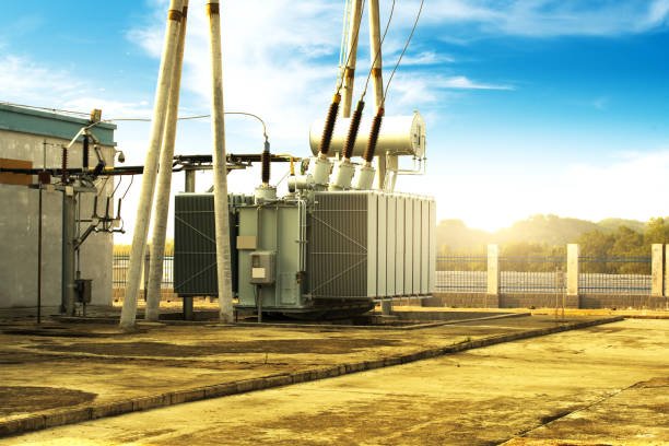
Selecting the wrong transformer voltage rating can lead to equipment incompatibility, insulation stress, poor voltage regulation, excessive losses, and potential electrical failures. Even when a transformer has sufficient capacity, an incorrect primary or secondary voltage rating can prevent it from operating properly within the existing power system. Buyers must therefore evaluate more than the nominal input and output voltages to ensure the transformer matches actual operating conditions, system configuration, and project requirements.
To select the right transformer voltage rating, buyers should identify the nominal primary and secondary system voltages, maximum and minimum operating voltages, frequency, phase configuration, winding connections, grounding arrangement, insulation level, and required voltage regulation. The selected transformer must match the system's voltage requirements and account for appropriate tap settings, voltage tolerances, and applicable electrical standards. Buyers should also verify the transformer nameplate, connection diagram, and test documentation before approving the equipment for installation.
Transformer voltage selection is a coordinated engineering decision rather than simply choosing two voltage values. Understanding the relationship between system voltage, winding configuration, insulation requirements, and load conditions helps buyers avoid specification errors and select a transformer that delivers reliable long-term performance.
How Do You Select the Right Transformer Voltage Rating Based on Primary and Secondary Voltages?
Selecting the wrong transformer voltage rating can cause equipment to receive insufficient voltage, operate above its design limits, overheat, or fail to perform reliably. Even when the primary and secondary voltage values appear correct, differences in three-phase connections, supply-voltage variation, loading, and tap settings can create unexpected results. Buyers can avoid these problems by identifying the actual system voltages, calculating the required transformation ratio, and verifying the transformer's rated operating conditions before placing an order.
To select the correct transformer voltage rating, match the primary rated voltage to the supply system and the secondary rated voltage to the load requirements. Calculate the nominal voltage ratio as primary voltage divided by secondary voltage, verify whether the specified values are phase-to-phase or phase-to-neutral, and confirm the phase configuration, frequency, tap range, voltage regulation, insulation level, and expected load current. For three-phase transformers, also check the winding connection and vector group because line-to-line voltage ratios may differ from the winding turns ratio.
A dependable selection process combines electrical calculations with the application's operating requirements. The following guide explains how to determine the correct primary and secondary voltage ratings, avoid common specification errors, and verify the proposed transformer before purchasing.
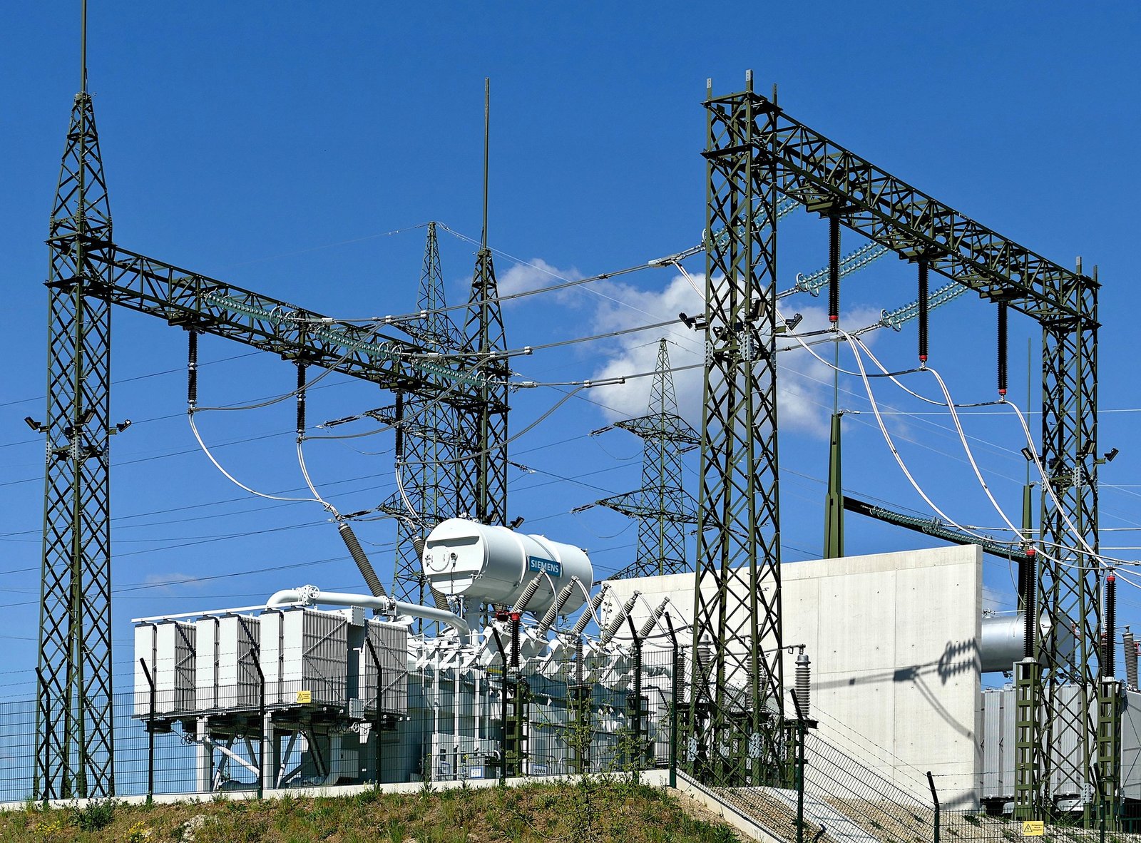
1. Identify the Actual Primary and Secondary System Voltages
The first step is to establish the voltage that the transformer will receive and the voltage required by the connected equipment. The primary voltage is the rated voltage applied to the input winding, while the secondary voltage is the rated voltage delivered by the output winding under the transformer's specified conditions.
Do not select a transformer solely from the voltage measured at one moment. Determine the nominal supply voltage, its permitted operating range, the required load voltage, and any expected variation caused by the upstream network or downstream load.
For example, an industrial facility may have a 480 V three-phase supply but require 208Y/120 V for equipment that uses both three-phase and single-phase loads. A suitable transformer must be specified for the actual primary and secondary system configuration, not just for a generic “480 V to 120 V” description.
| Application | Example primary rating | Example secondary rating | Key consideration |
|---|---|---|---|
| Industrial control power | 480 V | 120 V | Confirm control-circuit load and grounding |
| Low-voltage distribution | 480 V | 208Y/120 V | Specify three-phase connection and neutral |
| Commercial distribution | 11 kV | 400 V | Confirm utility voltage and local system requirements |
| Distribution step-up | 400 V | 11 kV | Verify insulation and network connection requirements |
These are illustrative examples, not universal recommendations. Actual ratings depend on the local supply system, applicable standards, load requirements, and manufacturer offerings.
2. Calculate the Required Transformer Voltage Ratio
For an ideal transformer, the voltage ratio corresponds to the ratio of turns in the respective windings:
[\frac{V_p}{V_s}=\frac{N_p}{N_s}]
Where:
- (V_p) = primary winding voltage
- (V_s) = secondary winding voltage
- (N_p) = primary winding turns
- (N_s) = secondary winding turns
Use consistent voltage quantities when applying this relationship. For a single-phase transformer, the primary and secondary rated voltages are normally compared directly. For a three-phase transformer, distinguish between winding phase voltages and system line-to-line voltages.
Consider a single-phase transformer rated 480 V primary and 120 V secondary:
[\text{Voltage ratio}=\frac{480}{120}=4]
The nominal ratio is therefore 4:1, meaning the primary voltage is four times the secondary voltage. In an ideal transformer, the secondary voltage is one-quarter of the primary voltage.
The actual terminal voltage may differ from the nominal value because of winding impedance, load current, power factor, and tap position. Therefore, the calculated ratio establishes the nominal design relationship; it does not guarantee an exactly constant secondary voltage under every operating condition.
3. Determine Whether You Need a Step-Up or Step-Down Transformer
A step-down transformer reduces voltage from the primary to the secondary, while a step-up transformer increases it. Choose the configuration according to the direction of power transfer and the voltage required by the receiving system.
| Transformer type | Voltage relationship | Typical applications |
|---|---|---|
| Step-down | Secondary voltage is lower than primary voltage | Industrial distribution, control power, equipment supplies |
| Step-up | Secondary voltage is higher than primary voltage | Generation interconnection, transmission interfaces, specialized power systems |
| Approximately 1:1 | Primary and secondary voltages are nominally equal | Voltage matching where the selected transformer design is appropriate |
A 1:1 voltage ratio does not establish galvanic isolation by itself. If electrical isolation is a safety or functional requirement, specify a conventional two-winding isolation transformer and verify its insulation design. An autotransformer has an electrically continuous winding and does not provide galvanic isolation.
4. Check Three-Phase Connections and Voltage Definitions
Three-phase voltage specifications require particular care. A transformer's turns ratio applies to corresponding winding phase voltages, but system ratings are often stated as line-to-line voltages. Depending on the winding connections, these values may not have the same numerical ratio.
For example, a star-connected winding has a line-to-line voltage that is (\sqrt{3}) times its phase voltage under a balanced operating condition. A delta-connected winding has line-to-line voltage equal to winding phase voltage.
Consequently, a three-phase transformer with star and delta windings may have a line-voltage ratio that differs from its winding turns ratio. Buyers should not calculate winding turns or verify a three-phase rating using line voltages alone without considering the connection arrangement.
Confirm the following details in the specification:
- Primary and secondary line-to-line voltages.
- Whether a neutral is required on either side.
- Star or delta winding connections.
- Vector group or phase displacement, where applicable.
- Phase sequence and grounding arrangement.
- Compatibility with the connected loads and protection system.
For a three-phase transformer, the line-to-line voltage ratio is always identical to the winding turns ratio, regardless of winding connections.False
The turns ratio relates corresponding winding phase voltages. Star and delta connections can introduce a square-root-of-three factor between phase and line-to-line voltages.
5. Account for Supply Variation, Taps, and Voltage Regulation
The nominal primary rating should match the intended supply system, but the real supply voltage may vary. Buyers should identify the acceptable input-voltage range and determine whether the transformer needs adjustable taps to maintain the required secondary voltage.
A tap changer adjusts the effective turns ratio. Depending on the design, it may be an off-circuit tap changer that requires de-energization or an on-load tap changer designed for adjustment while energized. Never assume that all tap changers can be operated under load.
Voltage regulation also matters. As load current flows through winding resistance and leakage reactance, secondary terminal voltage can change. The magnitude and direction of this change depend partly on load power factor.
Ask the manufacturer to provide voltage-regulation data for the intended load conditions, the available tap positions, the voltage adjustment range, and the operating instructions for the tap-changing mechanism.
6. Verify Frequency, Insulation Level, and Load Capacity
Voltage rating cannot be considered independently of frequency. At a given winding turns count, lowering frequency while maintaining the same voltage increases magnetic flux density, potentially causing core saturation and excessive magnetizing current. Confirm that the rated frequency matches the supply, especially when equipment is intended for use across different regions or on specialized power systems.
The insulation level must also suit the highest system voltage and expected electrical stresses. For medium- and high-voltage transformers, request the applicable insulation and dielectric-test requirements rather than relying only on the nominal voltage printed on a datasheet.
Finally, ensure that the transformer has enough kVA capacity for the connected load. Voltage compatibility does not guarantee sufficient current capability. Consider continuous demand, peak loading, motor-starting current, nonlinear loads, ambient temperature, altitude, and expected future expansion.
7. Use a Practical Verification Checklist Before Ordering
Before approving a quotation, ask the supplier to confirm each of the following items in writing.
| Check | Information to confirm |
|---|---|
| Primary rating | Nominal supply voltage and permitted operating range |
| Secondary rating | Required load voltage and neutral requirements |
| Voltage ratio | Calculated nominal ratio and winding configuration |
| Phase arrangement | Single-phase or three-phase, winding connections, and vector group |
| Frequency | Rated supply frequency |
| Capacity and current | kVA rating, rated currents, and load profile |
| Voltage control | Tap range, tap positions, and adjustment method |
| Regulation | Expected secondary-voltage performance under load |
| Insulation | Rated insulation level and applicable dielectric tests |
| Documentation | Datasheet, connection diagram, routine test reports, and applicable compliance documents |
A useful purchasing specification states the complete electrical configuration rather than only a pair of voltage numbers. This makes it easier to compare quotations on an equivalent basis and reduces the risk of receiving equipment that cannot be connected directly to the intended system.
How Do You Select the Right Transformer Voltage Rating Based on Operating Voltage Variations?
Choosing a transformer based only on the nominal supply voltage can cause problems when the actual operating voltage fluctuates. A sustained low input voltage may leave the secondary voltage too low for motors or control equipment, while a sustained high voltage can increase magnetic flux and create excessive operating stress. If the transformer’s tap range, voltage ratio, or regulation capability is unsuitable, connected equipment may experience unreliable operation, nuisance trips, or reduced service life.
To select the right transformer voltage rating for operating voltage variations, determine the minimum, nominal, and maximum expected primary voltages, establish the acceptable secondary-voltage range under load, and choose a transformer with a suitable rated voltage, tap range, voltage regulation, kVA capacity, and frequency rating. Verify that the complete operating range remains within the manufacturer’s limits and that the secondary voltage meets the connected equipment’s requirements. If variations exceed the transformer’s adjustment capability, consider a suitable voltage regulator or other power-quality solution.
The key is to evaluate the transformer as part of the complete electrical system rather than as an isolated component. The following steps help buyers compare specifications, identify potential risks, and select equipment that can operate reliably under real-world conditions.
1. Determine the Actual Primary Operating Voltage Range
Start by collecting the expected primary supply voltage under normal operating conditions. A system’s nominal voltage is the design reference, but the actual voltage can change with utility loading, feeder impedance, large motor starts, and network operating conditions.
Identify three values:
- Minimum primary voltage: The lowest expected sustained input voltage.
- Nominal primary voltage: The stated system voltage.
- Maximum primary voltage: The highest expected sustained input voltage.
Where possible, use voltage measurements taken during different load conditions rather than relying entirely on estimates. Separate sustained variations from short-duration switching or lightning transients, because these require different protection and insulation considerations.
| Supply condition | Potential transformer effect | Selection consideration |
|---|---|---|
| Sustained low voltage | Secondary voltage may fall below the required level | Low-input operating range and tap settings |
| Sustained high voltage | Secondary voltage may become excessive; core flux may increase | High-input operating limits and frequency |
| Motor starting | Temporary voltage dip under high current demand | Starting duty and system impedance |
| Changing load | Secondary voltage varies with load current | Voltage regulation |
| Frequent wide variations | Fixed taps may not maintain acceptable output | Adjustable taps or a separate regulator |
2. Define the Required Secondary-Voltage Range
Determine the voltage required by the equipment connected to the transformer. Motors, control circuits, electronic equipment, and sensitive instruments may have different voltage tolerances, so use the equipment manufacturer’s specified limits.
Define the minimum, nominal, and maximum acceptable secondary voltages. Where cables connect the transformer to distant loads, account for cable voltage drop so that the voltage at the equipment—not merely at the transformer terminals—remains acceptable.
For example, a facility using a nominal 400 V load supply should confirm the equipment’s permitted voltage range and assess whether the proposed transformer can maintain that range during both light-load and heavy-load conditions. The acceptable limits must come from the actual equipment and project requirements rather than an assumed universal percentage.
3. Calculate the Nominal Voltage Ratio
For an ideal transformer, the ratio of corresponding winding voltages is equal to the ratio of winding turns:
[\frac{V_p}{V_s}=\frac{N_p}{N_s}]
Here, (V_p) and (V_s) are the primary and secondary winding voltages, while (N_p) and (N_s) are their respective turns counts.
Consider a single-phase transformer with a 480 V primary and a 240 V secondary:
[\frac{V_p}{V_s}=\frac{480}{240}=2]
The nominal ratio is 2:1. Ideally, the secondary voltage is half the primary voltage.
However, the nominal ratio does not by itself guarantee acceptable secondary voltage when the supply changes. Winding impedance, load current, power factor, and tap position also affect terminal voltage.
For three-phase transformers, take special care to distinguish winding phase voltage from system line-to-line voltage. Star and delta connections can produce different line-voltage ratios for the same winding turns ratio.
4. Check the Tap Range and Adjustment Method
Transformer taps alter the effective turns ratio and can compensate for certain predictable supply-voltage differences. Buyers should confirm the available tap positions, adjustment increments, total adjustment range, and permitted operating method.
Some transformers use off-circuit taps that require de-energization before adjustment. Others have on-load tap changers specifically designed for adjustment while energized. Never assume that an ordinary tap changer can be operated under load.
A useful preliminary calculation is the percentage deviation of the measured primary voltage from its nominal value:
[\%\Delta V_p=\
\frac{Vp-V_{p,\mathrm{nom}}}{V\{p,\mathrm{nom}}}\times100]
This calculation indicates the magnitude and direction of the input-voltage deviation. It does not prove that a particular tap setting will maintain the required output voltage. The final check must include the manufacturer’s tap definitions, the selected turns ratio, expected load, and voltage regulation.
5. Evaluate Voltage Regulation and Load Capacity
Even if the primary voltage is stable, the secondary terminal voltage can change as load current increases. Winding resistance and leakage reactance cause voltage drops, with the effect depending partly on the load power factor.
Request the manufacturer’s voltage-regulation data for the intended load conditions. Check rated kVA and winding current as well: a transformer with the correct voltage ratio can still be unsuitable if the load exceeds its thermal capacity.
For single-phase systems:
[\S=VI]
For balanced three-phase systems:
[\S=\sqrt{3}V_{LL}I]
where (S) is apparent power, (V_{LL}) is line-to-line voltage, and (I) is line current.
For motor-starting applications, provide the starting current, starting duration, torque requirements, and expected number of starts. These details help the manufacturer determine whether the transformer can handle the duty without unacceptable voltage drop or overheating.
6. Verify Frequency and Insulation Requirements
Voltage rating must be compatible with the supply frequency. At the same winding turns count, applying the same voltage at a lower frequency increases magnetic flux density. If the transformer is not designed for that condition, core saturation, excessive magnetizing current, and overheating may result.
Confirm the rated frequency and any manufacturer-approved voltage/frequency operating limits. Also verify the required insulation level, dielectric withstand requirements, and surge protection for the installation.
Ambient temperature, altitude, cooling method, enclosure conditions, harmonics, and duty cycle may also affect the permissible loading or require derating. These factors should be included in the specification before the transformer is ordered.
A transformer tap changer can always correct any sustained primary-voltage variation without affecting transformer loading or operating limits.False
Tap adjustment is limited by the transformer's available range and design. It cannot compensate for every voltage variation, and operating limits, loading, and the approved tap-changing method must be respected.
7. Decide Whether a Separate Voltage-Regulation Solution Is Needed
Transformer taps are useful when supply variations are predictable and fall within the available adjustment range. They may be insufficient when voltage changes are rapid, frequent, or wider than the transformer’s approved operating range.
Depending on the application, possible solutions include an automatic voltage regulator, an appropriately specified on-load tap-changing transformer, feeder improvements, or dedicated power-quality equipment. Short-duration transients require separate consideration and may need surge protection rather than tap adjustment.
The correct choice depends on the cause of the voltage variation, how quickly the output must respond, the sensitivity of the connected load, and the project’s cost and maintenance requirements.
Final Buyer Checklist
Before approving the transformer specification, verify:
- Minimum, nominal, and maximum primary operating voltages.
- Required secondary-voltage limits at the load terminals.
- Nominal voltage ratio and three-phase winding connections, where applicable.
- Tap range, tap increments, and adjustment method.
- Voltage regulation at the expected load and power factor.
- Rated kVA, winding currents, and starting or overload duty.
- Frequency, insulation level, cooling, and environmental conditions.
- Applicable standards, connection diagrams, and factory test documentation.
How Do You Select the Right Transformer Voltage Rating Based on Phase Configuration and Winding Connections?
Selecting a transformer voltage rating without considering phase configuration and winding connections can result in an incorrect secondary voltage, an incompatible neutral arrangement, unexpected phase displacement, or equipment that cannot operate correctly with the existing electrical system. These issues are particularly important in three-phase distribution networks, industrial plants, and commercial facilities where transformers must match both the system voltage and the way the windings are connected. A transformer with the correct nominal voltage numbers may still be unsuitable if its star or delta configuration does not match the application.
To select the correct transformer voltage rating based on phase configuration and winding connections, first identify whether the system is single-phase or three-phase, establish the required primary and secondary line-to-line and line-to-neutral voltages, and select compatible winding connections such as star (Y) or delta (Δ). Then verify the winding turns ratio, neutral availability, vector group and phase displacement, grounding method, frequency, rated kVA, and insulation level. For three-phase transformers, calculate voltage ratios using consistent phase or line-voltage quantities because star and delta connections can introduce a factor of (\sqrt{3}) between winding phase voltage and line-to-line voltage.
A reliable selection process therefore starts with the electrical system diagram rather than a voltage label alone. The following guide explains how phase configuration and winding connections affect transformer ratings, how to interpret common voltage combinations, and what buyers should verify before ordering.
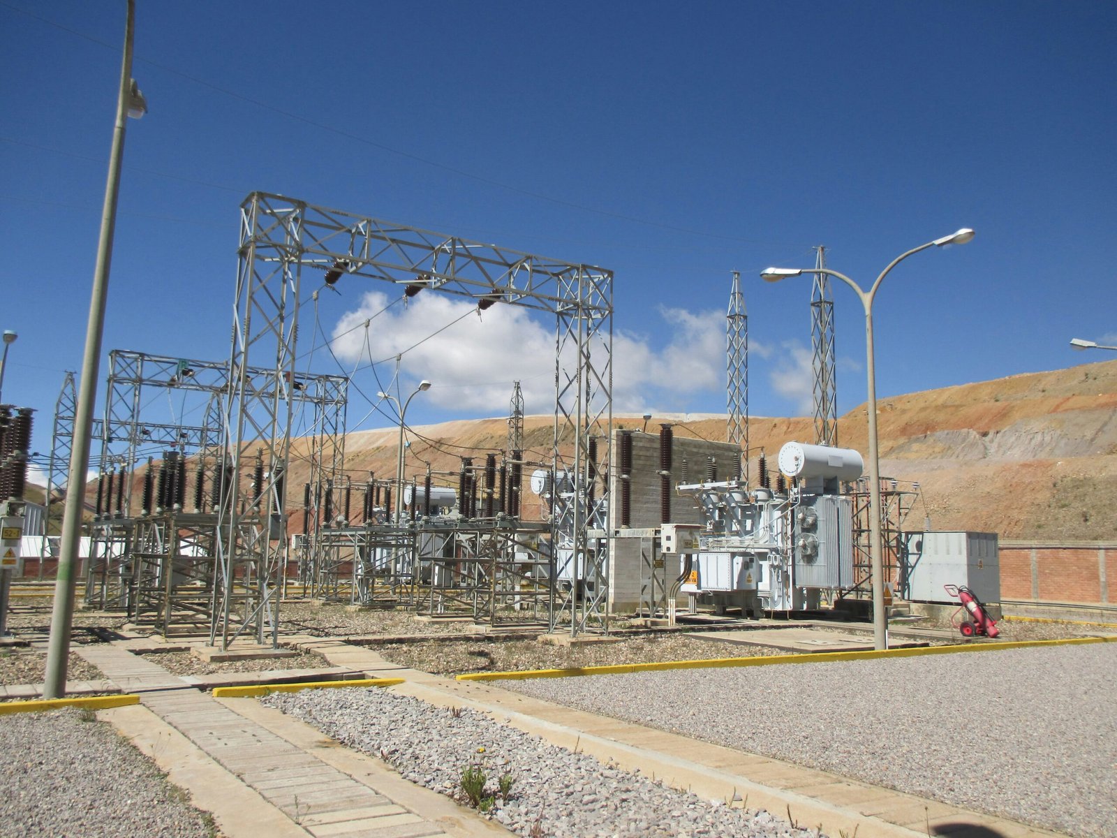
1. Identify the Phase Configuration of the Electrical System
Before choosing the transformer voltage rating, determine whether the source and load use single-phase or three-phase power. Single-phase transformers are commonly used for individual loads, control circuits, and smaller distribution requirements. Three-phase transformers are widely used for industrial machinery, commercial distribution, and larger power systems.
For a single-phase transformer, the primary and secondary voltage ratings usually refer directly to the voltages across their respective windings or terminals, subject to the stated connection arrangement.
For a three-phase transformer, the system voltage is commonly specified as line-to-line voltage. However, the voltage across each individual winding depends on whether the winding is connected in star or delta. This distinction is essential when specifying the transformer ratio.
| System configuration | Typical voltage specification | Key selection consideration |
|---|---|---|
| Single-phase | Primary and secondary terminal voltages | Match the supply and load voltages |
| Three-phase, star-connected secondary | Line-to-line and possibly line-to-neutral voltages | Confirm neutral availability and grounding |
| Three-phase, delta-connected secondary | Line-to-line voltage | Confirm whether a neutral is needed |
| Three-phase, mixed Y–Δ connections | System voltages on both sides | Account for the connection-dependent phase-voltage relationship and phase displacement |
The examples in this article illustrate common principles. Actual ratings and connections must be selected according to the utility supply, load requirements, grounding arrangement, and applicable standards.
2. Understand the Difference Between Line Voltage and Phase Voltage
For a balanced three-phase star-connected winding, the line-to-line voltage is (\sqrt{3}) times the phase voltage:
[\V_{LL}=\sqrt{3}V_{ph}]
Therefore:
[\V_{ph}=\frac{V_{LL}}{\sqrt{3}}]
For a delta-connected winding, the line-to-line voltage equals the winding phase voltage:
[\V_{LL}=V_{ph}]
These relationships explain why a transformer's line-voltage ratio may not be identical to its winding turns ratio when the primary and secondary connections differ.
For example, consider a three-phase transformer with a 480 V line-to-line primary connected in delta and a 208Y/120 V secondary connected in star. The primary winding phase voltage is 480 V, while the secondary winding phase voltage is approximately 120 V. The corresponding winding voltage ratio is therefore approximately 4:1, whereas the line-to-line voltage ratio is:
[\frac{480}{208}\approx2.31]
Both values describe the same transformer from different voltage reference points. The distinction matters when checking winding turns, ordering replacement equipment, or interpreting nameplate data.
3. Select the Appropriate Star or Delta Winding Connection
Star and delta connections provide different electrical characteristics, so the correct choice depends on the system's voltage requirements, neutral needs, grounding method, and phase-displacement requirements.
A star-connected winding has a common connection point that can provide a neutral when the transformer and system design permit it. This can be useful for supplying both line-to-line and line-to-neutral loads.
A delta-connected winding forms a closed three-phase loop. It does not inherently provide a neutral terminal, although some specialized delta arrangements can provide a neutral through a suitable winding configuration. Delta connections can also provide a path for certain circulating triplen harmonic currents, depending on the transformer design and system conditions.
| Winding connection | Main characteristics | Common applications |
|---|---|---|
| Y–Y | Star on both sides; neutral may be available on either side if designed for it | Systems requiring compatible star connections |
| Δ–Δ | Delta on both sides; no inherent neutral | Three-phase loads that do not require a neutral |
| Δ–Y | Delta primary, star secondary; secondary neutral may be available | Distribution systems supplying line-to-line and line-to-neutral loads |
| Y–Δ | Star primary, delta secondary | Industrial applications requiring a delta-connected secondary |
| Zigzag | Special interconnected winding arrangement | Grounding and neutral-reference applications where appropriately designed |
These configurations are not interchangeable simply because their voltage ratings appear similar. Each must be checked for system compatibility, grounding, harmonic performance, and phase displacement.
4. Verify the Voltage Ratio for the Actual Winding Connections
For an ideal transformer, the voltage across corresponding windings follows the turns ratio:
[\frac{V_{p,ph}}{V_{s,ph}}=\frac{N_p}{N_s}]
Here, (V_{p,ph}) and (V_{s,ph}) are the primary and secondary winding phase voltages. For a single-phase transformer, this reduces to the familiar relationship between primary and secondary winding voltages.
When selecting a three-phase transformer, convert line-to-line voltages to the corresponding winding phase voltages before comparing turns ratios. For a star winding, divide the line-to-line voltage by (\sqrt{3}). For a delta winding, the winding phase voltage equals the line-to-line voltage.
The line-to-line voltage ratio of a three-phase transformer always equals its winding turns ratio, regardless of whether the windings are connected in star or delta.False
The turns ratio relates corresponding winding phase voltages. Star and delta connections relate phase voltage to line-to-line voltage differently, so the system line-voltage ratio can differ from the winding turns ratio.
The transformer nameplate should identify the rated voltages and winding connections clearly. If the project specifies both line-to-line and line-to-neutral loads, confirm that the secondary connection supplies the required voltages without exceeding the winding or neutral ratings.
5. Check Vector Group and Phase Displacement
A three-phase transformer's vector group identifies its winding connection arrangement and the phase displacement between the primary and secondary systems. This is particularly important when transformers will operate in parallel or connect to an existing network.
Two transformers may have matching primary and secondary voltage magnitudes but still be incompatible for parallel operation if their phase displacement or vector groups differ. Before selection, verify:
- Primary and secondary winding connections.
- Vector group and phase displacement.
- Phase sequence.
- Polarity and terminal markings.
- Compatibility with existing transformers and connected equipment.
For parallel operation, matching voltage ratio alone is insufficient. Buyers must also verify compatible vector groups, polarity, phase sequence, percentage impedance, and impedance angle, along with any other project-specific requirements.
6. Confirm Neutral, Grounding, and Protection Requirements
The winding connection affects whether a neutral is available and how the transformer interacts with the system grounding arrangement. This can influence earth-fault current, protective-device operation, and the voltage of each phase relative to earth.
If the load requires a four-wire system, such as a three-phase supply with line-to-neutral loads, confirm that the proposed secondary is designed to provide the required neutral and that the neutral conductor and terminals have appropriate ratings.
For systems that require a defined grounding reference, evaluate whether a grounded star winding, grounding transformer, or another grounding arrangement is needed. Do not assume that every star-connected winding is automatically grounded or that every delta-connected system is unsuitable for all neutral-related applications.
Protection should be coordinated with the transformer voltage rating, winding connections, available fault current, and the connected network. The complete system design must meet the applicable electrical standards and local code requirements.
7. Verify kVA Rating, Frequency, and Insulation Level
Correct phase configuration and voltage ratio do not guarantee adequate capacity. Confirm the rated kVA or MVA, primary and secondary currents, load profile, motor-starting duty, and expected future demand.
For balanced three-phase systems, apparent power is calculated as:
[\S=\sqrt{3}V_{LL}I]
where (S) is three-phase apparent power, (V_{LL}) is line-to-line voltage, and (I) is line current.
Also verify the rated frequency. Operating a transformer at a lower frequency without an appropriate voltage adjustment or design approval can increase magnetic flux density and lead to saturation or overheating.
Finally, specify the insulation level and applicable dielectric withstand requirements for the system voltage and expected electrical stresses. Environmental conditions, cooling method, altitude, harmonics, and temperature rise may also affect the required design.
Transformer Voltage Selection Checklist
Before approving a transformer quotation, confirm:
- Single-phase or three-phase system configuration.
- Nominal primary and secondary line-to-line voltages.
- Required line-to-neutral voltages and neutral availability.
- Star, delta, or specialized winding arrangement.
- Winding turns ratio using consistent phase-voltage quantities.
- Vector group and phase displacement.
- Grounding method and protection requirements.
- Rated kVA, frequency, current, and insulation level.
- Tap range and voltage-regulation requirements.
- Nameplate data, connection diagrams, factory test reports, and applicable compliance documentation.
How Do You Select the Right Transformer Voltage Rating Based on Insulation Level and Frequency?
Selecting a transformer voltage rating without considering insulation level and operating frequency can create serious reliability and safety problems. A transformer may match the nominal supply voltage yet experience excessive magnetic flux, insulation stress, partial discharge, or overheating if its design is unsuitable for the actual electrical system. These risks are especially important in industrial plants, utility substations, renewable-energy installations, and applications where switching surges or unusual frequency conditions may occur.
To select the correct transformer voltage rating based on insulation level and frequency, first confirm the system’s nominal and maximum operating voltages, rated frequency, and expected voltage-to-frequency ratio. Then verify the transformer’s insulation level, dielectric withstand requirements, winding insulation design, and manufacturer-approved operating limits. A transformer must be suitable for both the electrical stresses imposed by the system and the magnetic flux produced at the intended voltage and frequency; matching the nominal voltage alone is not sufficient.
The safest approach is to treat voltage rating, insulation coordination, and frequency as related but distinct selection criteria. The voltage rating establishes the intended electrical operating conditions, insulation requirements address electrical stress and withstand capability, and frequency influences magnetic flux and core behavior. Understanding all three helps buyers compare specifications accurately and avoid unsuitable equipment.
1. Establish the Rated Voltage and Maximum System Voltage
Begin by identifying the nominal voltage of the supply and the voltage required by the connected load. Also determine the maximum system voltage relevant to the transformer’s insulation design.
These values are not always identical. For example, a transformer connected to a medium-voltage network must be selected using the applicable equipment voltage class and insulation requirements, not simply the nominal voltage printed on the utility diagram.
Buyers should establish:
- Primary and secondary rated voltages.
- Maximum normal operating voltage.
- Single-phase or three-phase configuration.
- Winding connections and grounding arrangement.
- Expected switching and transient overvoltages.
- Applicable system and equipment standards.
The primary and secondary ratings must match the intended electrical system, while the insulation system must be appropriate for the electrical stresses the equipment may encounter.
| Specification | What to verify | Why it matters |
|---|---|---|
| Rated voltage | Nominal primary and secondary voltage | Establishes the intended operating ratio |
| Maximum system voltage | Applicable maximum voltage for the equipment class | Helps determine insulation requirements |
| Grounding arrangement | Neutral grounding and earth-fault conditions | Influences phase-to-earth stress |
| Transient exposure | Switching surges and lightning-related stresses | Affects insulation coordination |
| Voltage regulation | Expected output under load | Helps maintain the required load voltage |
Do not assume that choosing a transformer with a higher nominal voltage automatically provides adequate insulation for every surge or grounding condition.
2. Understand Transformer Insulation Levels
Transformer insulation separates energized components from one another and from grounded structures. Its performance depends on insulation materials, clearances, creepage distances, winding construction, and the electrical stresses imposed during normal operation and abnormal events.
Insulation requirements may include power-frequency withstand and, for equipment exposed to relevant transient stresses, impulse withstand requirements. The applicable test levels depend on the transformer type, rated voltage class, insulation coordination, and governing standards.
Buyers should request the manufacturer's specified insulation level and corresponding test documentation. For medium- and high-voltage transformers, confirm the applicable insulation coordination requirements rather than relying on a generic description such as “high insulation.”
A transformer’s nominal voltage rating alone is sufficient to determine whether its insulation can withstand all expected electrical surges.False
Insulation coordination also depends on maximum system voltage, grounding, transient exposure, protective devices, equipment standards, and specified dielectric withstand levels.
The insulation level should be appropriate for the installation, but unnecessarily selecting a higher insulation class without an engineering basis may increase cost without solving other design issues.
3. Verify Rated Frequency and the Voltage-to-Frequency Ratio
Operating frequency affects the magnetic flux density in the transformer core. For a sinusoidal supply, the approximate relationship for a given winding is:
[\B_{\max}\propto\frac{V}{fN}]
where:
- (B_{\max}) is maximum core flux density.
- (V) is the winding voltage.
- (f) is supply frequency.
- (N) is the number of winding turns.
For a fixed winding, increasing voltage or reducing frequency increases core flux density. If the core is driven beyond its intended design range, it may saturate, causing higher magnetizing current, increased losses, noise, and overheating.
This is why the rated frequency must match the actual supply conditions. A transformer designed for 60 Hz should not automatically be operated at 50 Hz at the same voltage unless the manufacturer confirms that the operating condition is acceptable. Likewise, a transformer intended for 50 Hz should not be assumed suitable for every 60 Hz application without checking its complete ratings.
| Operating condition | Possible consequence | Required action |
|---|---|---|
| Rated voltage and rated frequency | Normal intended operation | Confirm nameplate compatibility |
| Same voltage at lower frequency | Increased core flux density | Obtain manufacturer approval or appropriate redesign |
| Higher voltage at the same frequency | Increased core flux density and insulation stress | Verify voltage and flux limits |
| Lower voltage at the same frequency | Reduced core flux density, but possibly insufficient load voltage | Check secondary-voltage requirements |
| Variable-frequency operation | Changing flux, losses, and cooling behavior | Specify the complete voltage-frequency operating profile |
The voltage-to-frequency ratio is particularly important in variable-frequency systems. A suitable transformer must be designed for the actual operating profile rather than only the nominal frequency.
4. Consider the Insulation System and Temperature Limits
Insulation materials have thermal limits, and transformer operating temperature affects insulation aging over time. Buyers should review the specified insulation thermal class, temperature-rise limits, cooling method, ambient temperature, and any required derating.
A transformer that is electrically compatible at its rated voltage and frequency may still be unsuitable if its cooling arrangement cannot dissipate the heat produced by the intended load.
For dry-type transformers, verify the insulation system, enclosure, ventilation, and suitability for dust, moisture, or corrosive environments. For liquid-immersed transformers, confirm the insulating liquid, cooling arrangement, leak containment, and applicable fire-safety provisions.
Where nonlinear loads are present, such as rectifiers or variable-frequency drives, provide the manufacturer with relevant harmonic information. Harmonic currents may increase winding and structural losses, requiring additional thermal evaluation or derating.
5. Check Primary and Secondary Insulation Requirements Separately
The primary and secondary windings may operate at different voltages and may be exposed to different phase-to-earth and transient stresses. Each side must therefore meet the insulation requirements appropriate to its system connection and operating conditions.
Confirm the following:
- Rated voltage of each winding.
- Applicable maximum system voltage.
- Winding connection and neutral arrangement.
- Insulation level and dielectric test requirements for each winding.
- Grounding method and expected earth-fault conditions.
- Required clearances, creepage distances, and terminal insulation.
- Applicable routine and special factory tests.
For three-phase transformers, line-to-line voltage and winding phase voltage must be distinguished when reviewing the voltage ratio. Star and delta connections affect the relationship between these values, while the grounding arrangement influences phase-to-earth stress.
If galvanic isolation is required, specify a suitable two-winding transformer and verify the insulation design accordingly. An autotransformer has a shared, electrically continuous winding and does not provide galvanic isolation.
6. Verify Applicable Standards and Factory Test Documentation
Before approving a quotation, identify the standards applicable to the transformer type, voltage class, installation, and jurisdiction. Relevant requirements may come from IEC or IEEE standards and local electrical codes, depending on the project.
Ask the manufacturer to provide a datasheet showing rated voltages, rated frequency, insulation levels, temperature-rise limits, cooling method, and applicable operating restrictions. Review the test schedule and confirm that the proposed unit will receive the required routine tests.
Depending on the transformer design and applicable standard, documentation may include winding resistance, turns ratio, polarity or phase-relation checks, insulation resistance, and specified dielectric withstand tests. Additional tests should be agreed upon where required by the project.
A test report should correspond to the actual transformer supplied or to the documented production and acceptance process agreed upon in the purchase specification. Do not rely on a generic compliance statement when specific ratings or test results are contractually required.
Final Buyer Checklist
Before selecting the transformer, confirm:
- Nominal and maximum system voltages.
- Required primary and secondary voltage ratings.
- Rated frequency and any permitted voltage-frequency range.
- Insulation level and dielectric withstand requirements.
- Winding connections, grounding, and phase-to-earth conditions.
- Cooling method, temperature rise, and environmental conditions.
- Load profile, harmonics, and expected duty cycle.
- Applicable standards and factory test documentation.
- Manufacturer approval for any nonstandard operating conditions.
How Do You Select the Right Transformer Voltage Rating Based on Tap Settings and Voltage Regulation?
Selecting a transformer based only on its nominal primary and secondary voltages can lead to poor voltage regulation when supply voltage fluctuates or the connected load changes. Equipment may receive undervoltage during peak demand or excessive voltage during light-load conditions, affecting motor performance, control systems, and electrical reliability. If the transformer’s tap range is unsuitable, adjusting the taps may not be enough to maintain the required output voltage.
To select the correct transformer voltage rating based on tap settings and voltage regulation, identify the minimum, nominal, and maximum primary voltages, establish the required secondary voltage under expected load conditions, and verify the transformer’s rated voltage, available tap positions, adjustment range, and guaranteed regulation performance. Confirm whether tap changes require de-energization or are permitted under load, and ensure the selected configuration maintains acceptable voltage across the expected operating range without exceeding the transformer’s electrical or thermal limits.
The best selection process combines system measurements, voltage calculations, load analysis, and manufacturer specifications. Understanding how tap settings and voltage regulation work together helps buyers choose a transformer that delivers the required voltage reliably rather than simply matching two nameplate values.
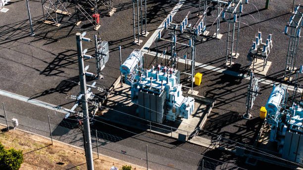
1. Establish the Primary Voltage Operating Range
Start by determining the voltage the transformer will actually receive. A nominal 480 V supply, for example, may vary as utility loading changes or large motors start. These variations affect the secondary voltage and determine whether the transformer needs a different tap setting or additional voltage-regulation equipment.
Identify three primary-voltage values:
- Minimum operating voltage: The lowest expected sustained input voltage.
- Nominal voltage: The normal system design voltage.
- Maximum operating voltage: The highest expected sustained input voltage.
Use recorded measurements when possible, especially during periods of high demand and light loading. Distinguish sustained voltage variation from short-duration switching surges, which require separate insulation and surge-protection considerations.
| Supply condition | Potential effect | Selection priority |
|---|---|---|
| Sustained low input voltage | Secondary voltage may fall below the required level | Low-voltage tap capability |
| Sustained high input voltage | Secondary voltage may become excessive | High-voltage tap capability and operating limits |
| Heavy load | Additional voltage drop through transformer impedance | Regulation performance at load |
| Light load | Secondary voltage may rise relative to loaded conditions | No-load and light-load voltage |
| Frequent fluctuations | A fixed tap may not maintain the desired output | Adjustable taps or a separate regulator |
The primary-voltage range should be evaluated together with the load-voltage limits, not independently.
2. Understand How Transformer Tap Settings Affect Voltage
Transformer taps change the effective number of winding turns used in the voltage transformation. Changing the turns ratio changes the secondary voltage for a given primary voltage.
For an ideal transformer:
[\frac{V_p}{V_s}=\frac{N_p}{N_s}]
where (V_p) and (V_s) are the corresponding winding voltages and (N_p) and (N_s) are the effective winding turns.
Consider a transformer with a nominal 480 V primary and a 240 V secondary. Its nominal primary-to-secondary voltage ratio is 2:1. If the primary supply is consistently below its nominal value, an appropriate manufacturer-provided tap setting may increase the effective secondary voltage. If the supply is consistently high, another setting may reduce it.
The direction and amount of correction depend on how the manufacturer defines the tap positions. Buyers should therefore request the actual tap table rather than assuming that a “+5%” label always means a particular terminal-voltage change without reference to the winding and rating convention.
Tap settings are generally intended to accommodate expected system conditions. They are not a substitute for correcting severe or rapid voltage fluctuations beyond the transformer's approved adjustment range.
3. Check the Available Tap Range and Adjustment Increments
The available tap range indicates how far the transformation ratio can be adjusted from its nominal setting. Common designs provide several discrete tap positions, but the available range and increments vary by transformer design and application.
Review these details before purchasing:
- Total tap adjustment range above and below nominal.
- Number of tap positions and adjustment increments.
- Whether taps are on the primary or secondary winding.
- The voltage reference used to define each tap.
- Whether adjustment requires de-energization.
- Whether an on-load tap changer is required for the application.
Many distribution transformers use off-circuit taps, which must be adjusted with the transformer de-energized and isolated according to the manufacturer's procedures. An on-load tap changer is designed for adjustment while energized and under load, but it adds complexity and requires its own operating and maintenance considerations.
| Requirement | What to verify |
|---|---|
| Stable supply with occasional commissioning adjustment | Suitable off-circuit tap range |
| Predictable long-term supply-voltage difference | Tap positions that cover the expected deviation |
| Frequent voltage variation requiring correction while energized | Whether an appropriate on-load tap changer or regulator is needed |
| Tight load-voltage limits | Tap range plus guaranteed regulation and downstream cable drop |
Do not select the widest available tap range automatically. The selected range should match the expected operating conditions and remain within the manufacturer's permitted voltage and flux limits.
4. Evaluate Voltage Regulation Under Actual Load Conditions
Tap settings establish the transformation ratio, but voltage regulation describes how the secondary terminal voltage changes as load current changes. Winding resistance and leakage reactance produce internal voltage drops, and the magnitude of the change depends partly on load power factor.
A transformer may provide the desired secondary voltage at no load but a lower voltage at full load. This is why the manufacturer's regulation data must be reviewed at the expected load and power factor.
For a simplified comparison, voltage regulation is often expressed as:
[\%\text{Regulation}=\
\frac{V_{\text{no-load}}-V_{\text{full-load}}}\
{V_{\text{full-load}}}\times100]
Use the manufacturer's specified definition when comparing guaranteed values, since conventions can differ. Also distinguish transformer-terminal voltage from the voltage at the connected equipment: cables and other downstream components can add further voltage drop.
For motor applications, check starting current and starting duration. High starting current can cause a temporary voltage dip even when the steady-state transformer rating and tap setting are appropriate.
5. Select the Tap Setting Using Both Input Voltage and Load Requirements
The correct tap setting should account for the actual primary supply and the secondary voltage required during the expected load range. A practical assessment includes minimum, nominal, and maximum input voltage, as well as light-load, normal-load, and peak-load conditions.
For each condition, verify that the predicted secondary voltage remains within the load’s permitted range. The calculation should use the manufacturer's tap data and regulation information, rather than assuming that output voltage changes by exactly the same percentage as input voltage under all loads.
A suitable transformer tap setting guarantees that the secondary voltage will remain constant regardless of primary-voltage variation and load changes.False
Taps adjust the effective transformation ratio, but their range is limited. Winding impedance, load current, power factor, and upstream voltage variation can still change the secondary voltage.
If the required output voltage cannot be maintained across the operating range, consider a different nominal voltage ratio, a wider approved tap range, an appropriate on-load tap changer, or a separate voltage regulator. The best option depends on how large and how quickly the voltage changes, the sensitivity of the load, and the project’s maintenance requirements.
6. Confirm Frequency, kVA Capacity, and Thermal Limits
Voltage regulation and tap selection must also be compatible with the transformer’s magnetic and thermal design. Operating at a lower frequency while maintaining the same voltage increases magnetic flux density for a fixed winding turns count. This can lead to core saturation, higher magnetizing current, and overheating if the transformer is not designed for the condition.
Verify the rated frequency and any manufacturer-approved voltage/frequency operating limits. Confirm the rated kVA, winding currents, cooling method, temperature-rise limits, ambient temperature, and any required derating for altitude or enclosure conditions.
For nonlinear loads, such as rectifiers and variable-frequency drives, provide the manufacturer with relevant harmonic information. Harmonic currents may increase heating and affect the appropriate transformer selection.
A tap adjustment does not increase the transformer's rated kVA capacity or automatically permit operation outside its thermal limits.
7. Verify the Specifications Before Ordering
Before approving the quotation, request a technical datasheet that clearly states the nominal primary and secondary voltages, available tap positions, tap adjustment method, rated frequency, kVA capacity, and guaranteed voltage-regulation performance.
Confirm that the offered tap range covers the expected supply conditions and that the resulting output voltage is suitable for the connected equipment. Also review the connection diagram, winding configuration, insulation level, protection requirements, applicable standards, and factory test documentation.
For projects requiring automatic correction, specify the required response behavior and output-voltage tolerance explicitly. The manufacturer can then assess whether conventional taps, an on-load tap changer, or a separate regulator is the most suitable solution.
Transformer Tap and Regulation Selection Checklist
- Record minimum, nominal, and maximum primary voltages.
- Define the acceptable secondary-voltage range at the load.
- Verify the nominal voltage ratio and winding configuration.
- Confirm tap range, increments, and adjustment method.
- Review voltage regulation at expected load and power factor.
- Account for motor starting, cable voltage drop, and load variation.
- Check frequency, kVA rating, current, cooling, and thermal limits.
- Confirm applicable standards and required factory documentation.
How Can Buyers Verify the Correct Transformer Voltage Rating Before Purchasing?
Purchasing a transformer with the wrong voltage rating can cause installation delays, equipment malfunction, excessive voltage drop, or costly replacement. Even when a supplier’s quotation lists the expected primary and secondary voltages, important details such as three-phase winding connections, tap settings, frequency, and neutral requirements may be overlooked. Buyers who verify these specifications before issuing a purchase order can reduce technical risks and ensure that the transformer is compatible with the electrical system.
To verify the correct transformer voltage rating before purchasing, compare the supplier’s datasheet and nameplate information with the project’s electrical requirements. Confirm the primary and secondary rated voltages, phase configuration, winding connections, frequency, voltage ratio, tap range, voltage regulation, and insulation level. Check that the transformer’s kVA rating and current capacity match the expected load, and request the connection diagram, applicable compliance documentation, and relevant factory test reports before approving the order.
A systematic verification process helps buyers identify specification gaps before manufacturing begins. The following checklist explains how to review the electrical data, validate the voltage ratio, evaluate operating conditions, and confirm that the supplier’s proposed transformer meets the intended application.
1. Match the Transformer Ratings to the Project Requirements
Start with the approved electrical single-line diagram, load schedule, and equipment specifications. These documents establish the intended supply voltage, required output voltage, phase arrangement, frequency, and connected load.
Do not rely solely on a short description such as “480 V to 208 V transformer.” Confirm whether the secondary must provide a neutral, whether the load requires line-to-neutral voltage, and whether the transformer is intended for continuous distribution, motor starting, or another duty.
| Specification | What buyers should verify | Why it matters |
|---|---|---|
| Primary voltage | Nominal supply voltage and permitted operating range | Ensures compatibility with the source |
| Secondary voltage | Required load voltage and neutral arrangement | Ensures the load receives the correct supply |
| Phase configuration | Single-phase or three-phase | Determines electrical connection requirements |
| Winding connections | Star (Y), delta (Δ), or another specified arrangement | Affects voltage relationships and grounding |
| Frequency | 50 Hz, 60 Hz, or another specified value | Affects magnetic flux and thermal performance |
| Rated capacity | kVA or MVA | Confirms the transformer's load capability |
The proposed transformer should match the project requirements as a complete electrical configuration, not just by nominal voltage values.
2. Verify the Voltage Ratio and Three-Phase Connections
For an ideal transformer, the ratio of corresponding winding voltages is equal to the ratio of winding turns:
[\frac{V_p}{V_s}=\frac{N_p}{N_s}]
For example, a single-phase transformer rated 480 V primary and 240 V secondary has a nominal primary-to-secondary voltage ratio of 2:1.
For three-phase transformers, buyers must distinguish winding phase voltage from system line-to-line voltage. In a star-connected winding:
[\V_{LL}=\sqrt{3}V_{ph}]
In a delta-connected winding:
[\V_{LL}=V_{ph}]
Therefore, a three-phase transformer’s line-voltage ratio may differ from its winding turns ratio when the primary and secondary connections differ. Confirm the connection symbols, vector group, phase displacement, and terminal markings on the supplier’s documentation.
If the transformer will operate in parallel with an existing unit, also verify compatible voltage ratios, tap settings, polarity, phase sequence, vector group, and percentage impedance. Matching the voltage ratio alone is not sufficient for safe parallel operation.
3. Check Tap Settings and Operating Voltage Variations
A transformer’s nominal voltage ratio does not guarantee that the secondary voltage will remain constant under all operating conditions. Primary voltage fluctuations, winding impedance, load current, and power factor can affect the actual secondary terminal voltage.
Ask the supplier to provide the available tap positions, adjustment increments, total adjustment range, and tap-changing method. Confirm whether taps are designed for off-circuit adjustment or on-load operation; never assume that a tap changer can be operated while energized.
Buyers should also compare the transformer’s voltage-regulation data with the connected equipment’s permissible voltage range. If the expected supply variations exceed the available tap range, a different voltage ratio, a suitable on-load tap changer, or a separate voltage-regulation solution may be required.
4. Confirm Rated Current, kVA Capacity, and Load Duty
A correct voltage ratio does not guarantee sufficient current capacity. Verify the expected continuous demand, peak loading, motor-starting current, duty cycle, and planned future expansion.
For single-phase systems:
[\S=VI]
For balanced three-phase systems:
[\S=\sqrt{3}V_{LL}I]
where (S) is apparent power, (V_{LL}) is line-to-line voltage, and (I) is line current.
Check that the supplier’s rated kVA, winding currents, cooling arrangement, and temperature-rise limits are appropriate for the application. If the load includes variable-frequency drives, rectifiers, or other nonlinear equipment, disclose the harmonic characteristics so the manufacturer can assess additional heating and any required derating.
5. Verify Frequency and Insulation Level
Frequency and insulation requirements are essential parts of transformer selection. At a fixed winding turns count, applying the same voltage at a lower frequency increases magnetic flux density. If the transformer is not designed for that operating condition, it may experience core saturation, excessive magnetizing current, and overheating.
Confirm the rated frequency and any manufacturer-approved voltage/frequency operating limits.
The insulation level must also be suitable for the system’s maximum voltage and expected electrical stresses. Depending on the transformer type and application, request the applicable power-frequency and impulse withstand requirements, along with relevant dielectric-test documentation.
Do not assume that a higher nominal voltage rating automatically guarantees suitability for every transient or grounding condition. Insulation coordination must be assessed for the actual electrical system.
6. Review the Datasheet, Nameplate, and Connection Diagram
Before issuing a purchase order, obtain a complete technical datasheet and confirm that it agrees with the quotation. The final specification should clearly identify:
- Primary and secondary rated voltages.
- Rated frequency and phase configuration.
- Winding connections, vector group, and neutral terminals.
- Rated kVA and winding current.
- Percentage impedance and applicable tolerance.
- Tap positions and adjustment method.
- Insulation level, cooling method, and temperature-rise limits.
- Enclosure, accessories, protection requirements, and installation conditions.
Request a connection diagram showing terminal markings and the intended wiring arrangement. Check that the proposed connection matches the project drawings and that the required neutral and grounding provisions are available.
A transformer quotation that lists the correct primary and secondary voltages is sufficient to confirm that the transformer is suitable for the application.False
Voltage values alone do not establish compatibility with phase configuration, winding connections, frequency, taps, insulation, load capacity, impedance, or grounding requirements.
7. Request Applicable Compliance Documents and Factory Test Reports
Ask the manufacturer which standards apply to the specific transformer type, voltage class, and installation jurisdiction. Depending on the project, relevant requirements may include applicable IEC or IEEE standards and local electrical codes.
Review the agreed factory test schedule and request the corresponding documentation. Depending on the design and applicable standards, routine testing may include winding resistance, turns-ratio verification, polarity or phase-relation checks, insulation tests, and specified dielectric withstand tests.
Confirm that the documentation corresponds to the offered transformer model and the ratings being purchased. If special tests or witnessed factory acceptance testing are required, agree on these requirements before the order is finalized.
A datasheet confirms the proposed design; the agreed test and compliance documentation helps demonstrate that the supplied equipment meets the specified requirements.
Final Transformer Voltage Verification Checklist
Before approving the purchase, confirm:
- Primary and secondary voltages match the project drawings.
- Phase configuration, winding connections, and vector group are correct.
- Line-to-line and line-to-neutral voltage requirements are satisfied.
- Frequency and operating voltage range are compatible.
- Tap range and voltage regulation meet the application requirements.
- Rated kVA and current capacity support the expected load.
- Impedance, insulation, cooling, and temperature-rise limits are suitable.
- Neutral, grounding, and protection arrangements are confirmed.
- Connection diagrams and nameplate details have been reviewed.
- Applicable compliance documents and factory test reports are agreed upon.
Conclusion
Selecting the right transformer voltage rating requires matching the transformer to the electrical system's nominal voltages, operating range, phase configuration, frequency, insulation requirements, and voltage-regulation needs. Buyers should confirm primary and secondary ratings, winding connections, tap-changer arrangements, and applicable standards before finalizing the specification. A correctly rated transformer helps ensure equipment compatibility, reliable operation, and long-term electrical safety.
FAQ
Q1: What is a transformer voltage rating?
A transformer voltage rating specifies the designed operating voltage of its primary and secondary windings. It helps ensure compatibility with the power supply, connected equipment, and required insulation levels.
Q2: How do you choose the correct transformer voltage rating?
Match the primary voltage to the supply and the secondary voltage to the load requirements. Also consider system frequency, voltage fluctuations, grounding configuration, and applicable electrical standards.
Q3: What is the difference between primary and secondary voltage?
Primary voltage is applied to the input winding, while secondary voltage is delivered to the output circuit. Their relationship depends mainly on the transformer's turns ratio and operating conditions.
Q4: How does transformer voltage rating affect performance?
An appropriate rating supports reliable voltage conversion and insulation performance. Incorrect selection can cause unsuitable output voltage, excessive electrical stress, equipment malfunction, or insulation damage.
Q5: Should transformer voltage ratings account for future expansion?
Yes. Evaluate anticipated load growth and future system changes, but avoid excessive oversizing without technical justification. Confirm that the selected voltage ratings, capacity, and protection arrangements meet both current and planned requirements.
References
- IEC 60076-1 — Power Transformers: General
https://webstore.iec.ch/en/publication/588 - IEC 60076-2 — Power Transformers: Temperature Rise for Liquid-Immersed Transformers
https://webstore.iec.ch/en/publication/604 - IEC 60076-3 — Power Transformers: Insulation Levels and Dielectric Tests
https://webstore.iec.ch/en/publication/605 - IEC 60076-5 — Power Transformers: Ability to Withstand Short Circuit
https://webstore.iec.ch/en/publication/607 - IEEE C57.12.00 — General Requirements for Liquid-Immersed Distribution, Power, and Regulating Transformers
https://standards.ieee.org/ieee/C57.12.00/6962/ - IEEE C57.12.01 — General Requirements for Dry-Type Distribution and Power Transformers
https://standards.ieee.org/ieee/C57.12.01/6775/ - IEEE C57.12.80 — Terminology for Power and Distribution Transformers
https://standards.ieee.org/ieee/C57.12.80/7006/ - IEEE C57.12.90 — Test Code for Liquid-Immersed Distribution, Power, and Regulating Transformers
https://standards.ieee.org/ieee/C57.12.90/ - IEEE Technology Navigator — Power Transformers
https://technav.ieee.org/topic/power-transformers/ - U.S. Department of Energy — Electricity Delivery and Grid Systems
https://www.energy.gov/oe