Installing a power transformer involves more than just delivering equipment—it requires a carefully prepared site that meets structural, electrical, and environmental criteria. Proper site preparation ensures the safety, reliability, and longevity of the transformer, while reducing risks of failure, fire, or maintenance complications. This article outlines the key factors and requirements for selecting and preparing an installation site for power transformers.
What Are the Space and Layout Requirements for a Transformer Site?
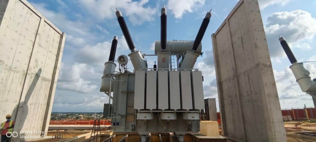
Proper transformer site layout and spacing are critical to safety, cooling efficiency, maintenance access, and regulatory compliance. Whether installing a compact distribution transformer or a high-voltage power unit, the site must be carefully planned to accommodate equipment footprint, fire protection, electrical clearance, oil containment, ventilation, and access paths.
Transformer site requirements include adequate space for the transformer body, radiators, cooling systems, and terminals; minimum safety clearances; oil containment systems; ventilation (for indoor units); access for maintenance and transport; and conformance with national electrical and fire codes. These parameters vary based on transformer size, voltage class, cooling type, and location (outdoor or indoor).
A well-designed transformer layout ensures safe, efficient, and future-proof operations.
Transformer installations can be placed tightly together without space planning.False
Transformers require safety, thermal, and maintenance clearances; improper spacing can cause overheating, arc hazards, or fire risk.
Key Components of Transformer Site Layout
| Layout Element | Description |
|---|---|
| Transformer Footprint | Base area of the tank, radiators, and attached equipment |
| Clearance Zones | Required distance from walls, fencing, and nearby equipment |
| Fire Walls or Barriers | Separate large transformers to contain potential fire spread |
| Oil Sump/Bund | Pit or bund wall to contain leaked or spilled oil (110% capacity) |
| Access Aisles | Maintenance and inspection pathways (≥1.5 m recommended) |
| Ventilation (Indoor) | Required airflow area for cooling systems (≥5 m³/s/MVA typical) |
| Cable Trenches | Subsurface ducts for HV/LV connections, control, and grounding cables |
| Foundation Pads | Concrete pads sized to support transformer weight and movement |
Typical Outdoor Site Clearances (IEC/IEEE Guidelines)
| Transformer Rating | Minimum Side Clearance | Front/Rear Clearance | Between Units |
|---|---|---|---|
| ≤1000 kVA (Outdoor) | 1.2 m | 1.5–2.0 m | 2.0 m |
| 1000–5000 kVA | 1.5 m | 2.5 m | 2.5–3.0 m |
| >5000 kVA or 132 kV+ | 2.5–3.0 m | 3.0–4.0 m | 3.5–5.0 m |
Always confirm with local codes (e.g., NEC, IEC 61936, IS 10028) for country-specific spacing.
Indoor Installation Requirements
| Indoor Factor | Space Requirement |
|---|---|
| Ceiling Height | ≥3.5 m clearance above top bushings (varies with voltage) |
| Ventilation Ducts | ≥1.2 m² cross-sectional airflow per 1000 kVA |
| Wall Distance | ≥1.5 m from transformer body (allow radiator air circulation) |
| Fire Barriers | Required between >500 kVA transformers or multiple units |
| Oil Detection Systems | Sump sensors + fire alarms if installed in buildings |
Foundation and Load Considerations
| Factor | Design Guidance |
|---|---|
| Dead Load | Support transformer weight (e.g., 10–30 tons for 20–100 MVA) |
| Dynamic Load Margin | Allow for transport shock or seismic resistance |
| Plinth Height | 300–600 mm above ground to prevent water pooling |
| Oil Sump Volume | 110% of total oil content, with oil-water separator |
Site Layout Example – 33/11 kV Substation Transformer
- Transformer: 10 MVA, oil-immersed, ONAN/ONAF
- Dimensions: 4.2 m × 2.4 m × 3.1 m (L×W×H)
Clearances:
- 3.5 m front for cable access
- 2.0 m rear to fencing
- 2.5 m between adjacent transformer
- Oil bund volume: 12,000 L (110% of oil content)
- Maintenance aisle: 1.5 m minimum on all sides
Result: Safe, ventilated, and code-compliant layout with future expansion room
Common Mistakes to Avoid
- ❌ Placing transformer too close to walls or fences → Blocks airflow, heat traps
- ❌ No oil containment system → Environmental hazard and legal violations
- ❌ Insufficient access → Maintenance delays, fire risk
- ❌ Inadequate ventilation (indoor) → Overheating, reduced life
- ❌ Ignoring fire barrier requirements between large units
What Grounding and Earthing Provisions Are Needed for Transformer Installations?
Grounding and earthing provisions are essential in transformer installations to ensure personnel safety, protect equipment from electrical faults, dissipate lightning or surge energy, and stabilize system voltage levels. Whether installed outdoors or indoors, every transformer must be integrated into a robust earthing system designed according to applicable standards.
Transformer grounding (or earthing) involves connecting the transformer's metal body, neutral point, and associated systems to the earth through conductors and electrodes to safely discharge fault currents, prevent electric shock, and protect equipment. This includes tank earthing, neutral grounding (via resistor, reactor, or direct connection), lightning arrester earthing, and ground grid integration with site fencing and control panels.
Neglecting proper grounding can lead to severe equipment damage, arc flash hazards, and regulatory non-compliance.
Transformer grounding is optional and not always required.False
Grounding is a mandatory electrical safety requirement defined by standards like IEC 61936, IEEE Std. 80, and NEC. It is essential for safety and fault protection.
Key Grounding Components and Their Functions
| Grounding Component | Function |
|---|---|
| Transformer Tank Earthing | Protects personnel from shock in case of internal fault |
| Neutral Earthing | Stabilizes system voltage and enables protection coordination |
| Lightning Arrester Grounding | Discharges surge energy from lightning or switching transients |
| Grounding Grid/Mat | Low-resistance network under site to evenly disperse fault current |
| Earthing Conductor | Copper/galvanized steel cable connecting equipment to grid |
| Test Links | Allow periodic resistance and continuity testing |
| Fence Earthing | Prevents voltage gradients and touch potential near site fence |
Types of Neutral Grounding
| Method | Application Scenario | Common Voltage Level |
|---|---|---|
| Solid Earthing | LV secondary of distribution transformers | <1 kV or 0.4 kV |
| Resistance Grounding (NER) | Medium/high voltage systems, limit fault current | 6.6 kV to 66 kV |
| Reactance Grounding | Large transformers with high inrush considerations | ≥33 kV |
| Ungrounded/Isolated | Special installations (e.g., detection systems) | Low-power industrial |
Recommended Earthing Practices by Transformer Type
| Transformer Type | Earthing Provisions |
|---|---|
| Oil-Immersed (Outdoor) | 2× tank earthing leads (min. 70 mm² Cu), LA earth, NER or direct N |
| Dry-Type (Indoor) | Body earthing, neutral to ground bar, lightning arresters for HV |
| Pad-Mounted Unit | Enclosure ground, neutral-earth bond in LV chamber |
| Grid Power Transformers | Full earth mat, interconnected mesh, NGR + surge protection |
Ground Resistance and Current Guidelines
| Parameter | Recommended Value |
|---|---|
| Ground Resistance | ≤1 ohm for substations; ≤5 ohms in general |
| Fault Current Path Duration | Max 3 seconds for high current clearing |
| Minimum Earthing Conductor Size | 70–120 mm² Cu or 95–240 mm² Al |
Standards Governing Transformer Earthing
| Standard | Title & Focus |
|---|---|
| IEC 61936-1 | Power Installations >1 kV AC (general grounding) |
| IEEE Std. 80 | Substation Grounding Design |
| IS 3043 | Indian Code of Practice for Earthing |
| NFPA 70 (NEC) | US National Electrical Code grounding practices |
Real-World Case – 132/33 kV Transformer Installation
- Site: Outdoor GIS substation
- Transformer: 100 MVA, oil-immersed, OFAF
Earthing provisions:
- 2× 120 mm² Cu earth leads to grid
- Neutral earthed via 20-ohm NER
- Lightning arresters earthed separately
- Ground grid resistance measured at 0.45 Ω
Result: Safe discharge of 17 kA fault, no equipment damage, compliant with IEC/IEEE design norms
Maintenance and Testing
| Action | Frequency |
|---|---|
| Earth Resistance Testing | Annually or post-rainfall |
| Continuity Check | During commissioning and outages |
| Inspection for Corrosion | Every 2–5 years |
| Grid Integrity Assessment | Every 5–10 years |
How Should the Foundation Be Designed for a Transformer?
A transformer's foundation is not merely a concrete slab—it is a precision-engineered support structure that must withstand static and dynamic loads, resist seismic and thermal stresses, contain oil in case of leaks, and accommodate proper grounding and access. A well-designed foundation ensures mechanical stability, electrical safety, fire containment, and long-term transformer integrity.
The foundation for a transformer must be designed to support the total operational weight (including oil and accessories), distribute loads evenly, resist settlement and vibration, provide oil containment, facilitate drainage, and incorporate earth bonding. Civil and structural engineers must consider soil conditions, transformer dimensions, anchoring requirements, and national codes when designing the foundation.
Ignoring proper foundation design can lead to structural damage, transformer misalignment, vibration issues, or environmental hazards.
Transformer foundations can be built without considering oil containment or dynamic load effects.False
Transformer foundations must include oil containment (bunds or pits) and account for dynamic forces like short-circuit torque or seismic loads, per civil and electrical codes.
Key Objectives of Transformer Foundation Design
| Design Element | Purpose |
|---|---|
| Load Support | Withstand static weight and dynamic forces (short-circuit, seismic) |
| Anchor and Stability | Prevent transformer movement during operation or fault |
| Oil Containment | Capture oil in bund or pit in case of leak or rupture |
| Grounding Integration | Allow connection of earth leads to substation grounding system |
| Thermal Isolation | Prevent heat buildup below the unit (via vents or air gaps) |
| Drainage Management | Prevent water pooling around or under transformer |
Standard Foundation Types
| Type | Description and Use Case |
|---|---|
| Raised RCC Plinth | Elevated pad with anchor bolts, typical for outdoor installations |
| Sunken Oil Pit | Concrete vault with oil containment and grate for indoor use |
| Bund Wall Foundation | Raised plinth within oil-proof bunded area with containment volume |
| Vibration-Isolated Pad | With elastomeric pads or grouted dampers for generator transformers |
Recommended Design Parameters
| Factor | Design Guideline |
|---|---|
| Dead Load Capacity | ≥1.5× transformer operational weight |
| Plinth Height | 300–600 mm above grade to prevent water ingress |
| Width Clearance | 300–500 mm extra on all sides for air circulation and access |
| Anchor Bolt Embedment | As per transformer base flange drawing (≥150 mm typical) |
| Concrete Grade | M25 or higher for structural durability |
| Reinforcement | Per IS 456 or ACI 318; seismic zones follow IS 1893/Eurocode 8 |
Oil Containment (Bund) Design
| Parameter | Minimum Standard |
|---|---|
| Bund Capacity | 110% of total transformer oil volume |
| Wall Height | 500–1200 mm with splash protection |
| Drainage | Sloped floor to oil sump (1–2% gradient) |
| Oil-Water Separator | Mandatory in most regions for environmental compliance |
| Fire Wall Between Units | 1.5 m high or noncombustible barrier between adjacent units |
Real-World Example – 33/11 kV 16 MVA Transformer Foundation
- Transformer weight: 21,800 kg (operating)
- Foundation: RCC plinth, 3.8 m × 2.5 m, height 500 mm
- Anchor bolts: 8 pcs M30, 250 mm embedded
- Oil bund volume: 10,200 liters (110% of 9200 L oil)
- Earth grid embedded with 4 × copper strips around pad
Result: Stable base, excellent oil containment, approved by grid utility and fire department, and ready for SCADA oil leak alarms.
Considerations for Special Installations
| Environment Type | Foundation Adaptation |
|---|---|
| Seismic Zone | Deeper footing, wider pad, ductile detailing (IS 1893) |
| Coastal/Marine Site | Salt-resistant concrete mix, anti-corrosion rebar |
| Indoor Basement | Oil-tight pit, gas detectors, ventilation path |
| Extreme Cold | Frost protection with insulation or trench heater pipes |
Maintenance and Inspection Checklist
| Activity | Frequency |
|---|---|
| Anchor Bolt Torque Check | Annually or after major load change |
| Oil Sump Cleaning | Every 6–12 months |
| Bund Integrity Check | After heavy rain or oil event |
| Drainage Clearance | Quarterly |
| Foundation Cracks | Visually every year |
What Environmental and Safety Factors Must Be Considered for Transformer Installations?
A power transformer is not just an electrical asset—it is a potential source of heat, noise, chemical leaks, fire hazards, and electromagnetic disturbance. Therefore, every transformer installation must strictly comply with environmental and safety regulations designed to protect people, property, wildlife, and air/water quality. These factors influence site layout, containment design, insulation selection, cooling systems, noise mitigation, and access control.
Transformer installations must address environmental and safety factors such as oil spill containment, fire risk mitigation, noise control, arc flash hazard zones, grounding integrity, water ingress prevention, toxic gas emissions, and compliance with local environmental regulations. These provisions protect personnel, nearby infrastructure, and the surrounding ecosystem.
Failure to comply may result in equipment damage, legal liability, operational shutdown, or catastrophic safety incidents.
Environmental and safety measures for transformers are optional unless in protected areas.False
Environmental and safety provisions are mandatory under IEC, IEEE, OSHA, NFPA, and national codes for all transformer installations, regardless of location.
Key Environmental Factors to Address
| Environmental Risk | Mitigation Approach |
|---|---|
| Oil Leaks or Spills | Bund wall, concrete pit, oil-water separator, leak sensors |
| Groundwater Contamination | Impermeable oil containment lining, drainage control |
| Air Emissions (Indoor) | Gas detectors for SF₆ (if used), oil vapor monitors |
| Thermal Radiation | Adequate spacing, ventilated enclosures |
| Storm Water Runoff | Drainage slope, oil diversion trenches, bund overflows |
| Noise Pollution | Acoustic barriers, low-noise design, fan dampeners |
| Visual Impact | Compact enclosure or landscaping in urban settings |
Core Safety Measures for Personnel and Equipment
| Safety Concern | Protective Measure |
|---|---|
| Arc Flash Hazard | Warning signage, flash boundaries (per IEEE 1584), PPE zones |
| Fire Risk | Fire-resistant oil (natural ester), stone bed or concrete base, foam system |
| Electrocution | Grounding of tank, fences, neutrals; isolation switches |
| Explosion Containment | Pressure relief devices, Buchholz relay, gas sensors |
| Access Control | Lockable fencing, smart keys, CCTV, zone alarms |
| Maintenance Safety | Safe clearances, mechanical interlocks, remote tap changers |
Noise and EMF Exposure Compliance
| Parameter | Limit/Guideline | Mitigation |
|---|---|---|
| Sound Level (dBA) | ≤55–65 dBA at 1 m for distribution transformers | Acoustic enclosures, fan silencers |
| EMF Field (µT) | Typically ≤100 µT at fence perimeter | Distance, shielding with metal barriers |
| Thermal Surface Limits | ≤60 °C touch-safe in accessible areas | Barriers, insulated sleeves |
Fire & Oil Spill Containment Requirements
| Provision | Minimum Requirement per Standard |
|---|---|
| Oil Bund Volume | ≥110% of total oil volume per IEC 61936/IS 3034 |
| Separation Between Units | ≥3 m or 1.5 m with 2 h-rated fire wall |
| Fire Suppression System | Foam sprinkler or fire detection if indoors or >5 MVA |
| Spill Sensors & Alarms | Oil leak detectors with remote SCADA alerts |
| Bund Drainage | Oil-water separator with sampling chamber |
Safety Clearance Zones
| Element | Minimum Clearance Requirement |
|---|---|
| Live Terminal to Fence | ≥3.0 m (up to 132 kV), ≥5.0 m (>220 kV) |
| Access Aisle Width | ≥1.5 m for maintenance path |
| Fire Access Route | 4.0 m wide emergency lane with turning radius |
| Safe Distance from Public | As per electromagnetic and arc flash limits |
Real-World Implementation – Substation Near Water Body
- Transformer: 33/11 kV, 16 MVA, oil-immersed, ONAN/ONAF
- Environment: Proximity to freshwater lake
Measures Taken:
- Double-bunded foundation with liner and oil sump
- Oil sensor integrated with SCADA and audible alarm
- 2.4 m fire wall between units
- Tree-line acoustic barrier to reduce sound to <52 dBA
- Emergency shut-off switch placed at 10 m safe zone
Result: Zero oil discharge, 100% safety audit pass, certified by environmental protection agency and fire safety board
Codes and Regulations to Follow
| Standard | Relevance |
|---|---|
| IEC 61936-1 | General safety provisions for HV installations |
| IEEE Std. 980 | Containment for transformer liquids |
| NFPA 850 | Fire protection for electric generating plants |
| OSHA 1910 Subpart S | Electrical safety for personnel access |
| Environmental Acts | Local water/soil/air protection laws for spill and emission control |
What Are the Requirements for Accessibility and Transportation of Transformers?
Power transformers—especially those above 2 MVA—are heavy, oversized, and sensitive to impact and tilt, requiring detailed planning for site access, road conditions, lifting equipment, unloading area, turning space, and post-installation serviceability. Failure to ensure accessibility can lead to delays, damage, cost overruns, or even inability to install the unit safely.
Transformer accessibility and transportation requirements include a clear and stable access road, adequate turning radius for delivery vehicles, crane or jack access for unloading, sufficient platform space, lifting gear rated for transformer weight, obstacle-free cable trenching, and provisions for future maintenance access. These factors must be coordinated with civil, logistics, and electrical teams early in the project.
Transformers can be transported and placed without planning the access route or crane space.False
Due to their size, weight, and lifting needs, transformers require carefully planned access roads, crane platforms, and turning spaces. Unprepared sites risk delivery failure or equipment damage.
Transformer Transportation Considerations
| Factor | Requirement |
|---|---|
| Delivery Truck Type | Low-bed or hydraulic trailer, depends on transformer dimensions |
| Road Width | ≥4.5 m (minimum), up to 6–7 m for escort vehicles and curves |
| Turning Radius | ≥18 m for standard heavy trailer with rear steering |
| Road Slope Limit | ≤5% gradient preferred, ≤10% absolute max for loaded entry |
| Overhead Clearance | ≥5.0 m from bridges, trees, wires |
| Bridge Load Ratings | Confirm with transport authority if route includes bridgeways |
| Transport Frame Protection | Shock-absorbing wooden pads or steel base |
Transformer Unloading and Placement Requirements
| Element | Provision |
|---|---|
| Unloading Zone | Concrete or compacted gravel area (flat, level, ≥1.5× transformer footprint) |
| Crane Access | Minimum 5–7 m radius around transformer for boom and outriggers |
| Transformer Weight | Match crane SWL and lifting radius (e.g., 80 ton crane for 20–25 MVA units) |
| Lifting Lugs or Skids | Pre-aligned with transformer lifting points |
| Jack Entry (Optional) | For rail movement or jacking, 600–900 mm side clearance |
| Shock Risk Area | Personnel exclusion zone (≥10 m) during lifting |
Accessibility for Operation and Maintenance
| Access Zone | Recommended Dimension |
|---|---|
| Front (Cable Entry) | ≥2.5 m for safe cable terminations and gland work |
| Rear (Radiators) | ≥1.5–2.0 m for fan access, inspection, cleaning |
| Sides (Inspection) | ≥1.0–1.5 m for nameplate, tap changer, pressure relief access |
| Top (Bushing Access) | Ladder or stair with platform if top inspection is needed |
| Emergency Route | 1.2–1.5 m escape path around transformer, marked and lit |
Real-World Case – Delivery of 40 MVA Transformer
- Transformer size: 5.6 m × 2.7 m × 3.3 m (L×W×H), 31,200 kg
- Site: Industrial substation with limited corner access
Adjustments made:
- 45° turning pad with compacted base added
- Overhead lines temporarily lifted by utility during delivery
- 100-ton crane deployed with 12 m radius working space
- Transformer positioned in 6 hours without incident
Outcome: Transformer successfully delivered and energized within 24 hours of arrival, thanks to pre-cleared access and crane zone design.
Transformer Transport Route Checklist
| Item | Confirmed Requirement |
|---|---|
| ✓ Route survey complete | Bridges, tunnels, corners mapped and cleared |
| ✓ Road surface reinforced | Base stabilized if soft during rainy season |
| ✓ Weight permits obtained | Transportation license acquired for >30-ton units |
| ✓ Escort vehicle ready | For movement through public roads |
| ✓ Utility line coordination | Overhead lines raised, shielded, or temporarily disconnected |
| ✓ Transport insurance | Covers delivery and crane risks |
Standards and Guidelines
| Reference | Description |
|---|---|
| IS 10028-2 | Indian Code for Transformer Installation |
| IEC 60076-1 Annex | Transformer handling and installation basics |
| ISO 1496-2 | Transport and packaging dimensions |
| ASTM D6179 | Shock and vibration resistance in transport packaging |
| Crane Safety Guidelines | OSHA/ISO lifting zone safety and clearance planning |
Are There Utility and Cable Routing Considerations for Transformer Installations?
Transformers interface with a network of high-voltage (HV), low-voltage (LV), control, protection, and grounding cables. These utilities must be routed, segregated, protected, and accessible to ensure safe, reliable, and maintainable operations. Improper cable routing can lead to electromagnetic interference, overheating, mechanical damage, or operational hazards—particularly in high-power installations.
Transformer cable routing must provide clear, segregated, and protected paths for HV, LV, and control cables. It requires pre-designed underground or aboveground ducting, mechanical protection (trays or conduits), thermal allowance for cable current, minimum bending radii, shielding separation, and accessible junctions. Cable routing must also avoid oil bunds, drainage paths, and be coordinated with the grounding system.
This ensures safety, electrical performance, and long-term serviceability.
Transformers can be installed without planning cable routing if cables are flexible.False
Transformer cable routing must be pre-designed to avoid interference, heat buildup, mechanical damage, and ensure safe installation and maintenance access.
Primary Utility and Cable Types in Transformer Installations
| Cable/Utility Type | Description |
|---|---|
| HV Cables | High-voltage input/output (6.6 kV to 220 kV) |
| LV Cables | Secondary feeders (230 V to 11 kV), service power |
| Control/Relay Cables | Trip circuits, SCADA, RTUs, sensors |
| Earthing Strips | Copper/Aluminum for tank, NGR, fencing |
| Auxiliary Power | Fans, pumps, lighting, fire alarms |
| Drainage/Water Utilities | From bund sump or heat exchangers |
Cable Routing Design Best Practices
| Design Aspect | Recommended Practice |
|---|---|
| Underground Trenches | Reinforced, ventilated, water-proofed, ≥500 mm depth |
| Duct Bank Layout | Segregate HV, LV, and control cables with physical dividers |
| Minimum Bending Radius | ≥12× cable diameter for HV, ≥8× for control cables |
| Cable Tray Systems | Hot-dip galvanized trays with covers for exposed areas |
| Oil Bund Avoidance | Route outside oil catchment areas to prevent contamination |
| Crossing Protection | Use sleeves or concrete slabs when crossing access roads |
| Earthing Path Integration | Control cables to run parallel to earth strips, not HV paths |
Access and Maintenance Provisions
| Accessibility Feature | Requirement |
|---|---|
| Inspection Chambers | Every 20–25 m or junction point in underground paths |
| Pull Boxes | Required where cable length >40 m or route changes direction |
| Markers and Tags | All cables labeled at entry, mid-span, and terminations |
| Ventilation | Trenches ≥1500 mm wide should include natural air channels |
| Spare Conduits | ≥20% spare ducts for future cable expansion |
Coordination with Other Systems
| System Affected | Cable Routing Consideration |
|---|---|
| Transformer Cooling | Avoid routing under radiators or fan intakes |
| Fire Safety | Fire-rated cable insulation, flame-retardant trays |
| Noise and EMI | Keep signal/control cables ≥300 mm away from HV cables |
| Structural Footing | Trenches must not weaken transformer base pads |
| Storm Drainage | Prevent cable trench flooding; use sealed covers and slope |
Real-World Cable Routing Case – 33/11 kV Substation
- Transformer: 16 MVA ONAN/ONAF with 11 kV RMU
- HV path: 3-core 11 kV XLPE cable in 600 mm trench, steel tray with RCC cover
- LV path: 3x1C 400 mm² to busbar in separate parallel trench
- Control cables: 2×20 pair armoured to protection relay panel via 100 mm PVC conduit
- Earth strip: 50×6 mm Cu across trench base
Result: Safe, interference-free routing with SCADA connectivity, surge protection, and room for future cable expansion.
Cable Routing Distance Guidelines
| Cable Type | From Oil Pit | From Other Cables | From Foundation Wall |
|---|---|---|---|
| HV Cable | ≥1.0 m | ≥0.5 m separation | ≥0.3 m |
| LV Feeder Cable | ≥0.5 m | ≥0.3 m | ≥0.2 m |
| Control Cables | ≥0.5 m | ≥0.2 m from HV | ≥0.2 m |
| Earth Strip | Touching ground grid with copper lugs every 6–8 m |
International Standards for Cable Routing
| Standard | Description |
|---|---|
| IEC 60364 | Electrical installations – Low-voltage routing practices |
| IEEE C2 (NESC) | Cable trench design and protection requirements |
| NEC Article 300 | US code for cable raceways and conduits |
| IS 1255 | Indian Standard for power cable laying and jointing |
Conclusion
A well-prepared transformer installation site ensures not only mechanical stability and operational efficiency, but also compliance with safety standards and ease of future maintenance. Key considerations include structural integrity, proper grounding, environmental protection, and accessibility. By addressing these factors early in the project, power utilities and industrial users can avoid costly delays, reduce risks, and guarantee reliable long-term performance.
FAQ
Q1: What are the basic site requirements for installing a power transformer?
A1: Key requirements include:
Adequate space for transformer, radiators, and maintenance access
Level, reinforced concrete foundation capable of supporting full load
Proper ventilation to ensure heat dissipation
Accessibility for transport, crane lifting, and servicing
Security fencing or enclosure to prevent unauthorized access
All conditions must meet national safety codes and utility standards.
Q2: How much clearance is required around a power transformer?
A2: Typical clearances depend on voltage and cooling type, but generally:
At least 1.5–3 meters around the unit for safety and maintenance
Fire separation distance from buildings or other equipment
Adequate airflow space for radiators (especially in ONAN/ONAF systems)
Check local electrical codes (e.g., NEC, IEC, or IEEE) for specific minimums.
Q3: What foundation specifications are needed?
A3: Foundation should:
Be made of reinforced concrete with appropriate load-bearing capacity
Include anchor bolts for securing the transformer
Be designed to handle dynamic loading (vibration, seismic activity)
Include oil containment pits or bund walls in case of leaks
Drainage and waterproofing should be provided to prevent water pooling.
Q4: What grounding and electrical protections are required?
A4: Install a low-resistance grounding system (typically <1 ohm)
Use grounding grids or rods interconnected with transformer body and neutral
Include lightning arresters, surge protectors, and protective relays
Proper shielding and bonding to prevent step and touch voltages
These measures protect against fault currents, lightning, and equipment damage.
Q5: What environmental and safety considerations must be addressed?
A5: Keep transformers away from flood-prone zones and corrosive atmospheres
Provide oil spill containment, firewalls, and fire suppression systems
Ensure compliance with noise regulations
Install signage, barriers, and lighting for safety and visibility
Perform risk assessment and grounding analysis before installation
These factors ensure safe, long-term operation and environmental compliance.
References
"Transformer Installation Guide" – https://www.electrical4u.com/transformer-installation-requirements
"IEEE Std 979: Transformer Site Preparation" – https://ieeexplore.ieee.org/document/9215639
"NFPA 850: Fire Safety for Electrical Substations" – https://www.nfpa.org/850
"NREL: Guidelines for Transformer Siting in Renewable Projects" – https://www.nrel.gov/docs/transformer-installation-siting.pdf
"ScienceDirect: Environmental Risk Assessment of Transformer Sites" – https://www.sciencedirect.com/transformer-installation-requirements-analysis