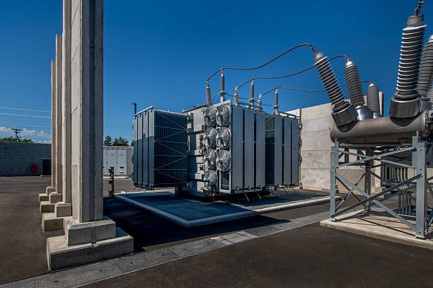
Transmitting electrical power over long distances at low voltage results in higher current, greater power losses, and increased voltage drop along transmission lines. These problems can reduce power-system efficiency and increase operating costs. A step-up transformer addresses this challenge by increasing voltage before electricity enters the transmission network, helping utilities and power producers deliver energy more efficiently.
A step-up transformer is an electrical transformer that increases AC voltage from its primary winding to its secondary winding while reducing current proportionally, assuming approximately constant power. It works through electromagnetic induction, with more turns on the secondary winding than on the primary winding. Step-up transformers are commonly used at power generation stations, renewable energy facilities, industrial power systems, and high-voltage transmission substations to raise voltage for efficient electricity transmission and distribution.
Understanding how a step-up transformer works and where it is used helps engineers, project developers, and equipment buyers select the correct voltage ratio, capacity, insulation level, and cooling configuration. The following outline covers its operating principle, applications, technical requirements, and selection considerations.
What Is a Step-Up Transformer and What Is Its Basic Operating Principle?
In electrical power systems, transmitting electricity over long distances at relatively low voltage can result in excessive current, higher line losses, and inefficient power delivery. Choosing the wrong transformer can increase operating costs, create voltage problems, and place unnecessary stress on electrical equipment. A step-up transformer addresses this challenge by increasing AC voltage before power enters a transmission network. Understanding its operating principle, winding arrangement, voltage ratio, and practical limitations helps engineers and buyers select the right transformer for their applications.
A step-up transformer is an electrical device that increases alternating-current (AC) voltage from its primary winding to its secondary winding through electromagnetic induction. It has more turns on the secondary winding than on the primary winding, so its secondary voltage is higher. For an ideal transformer, the voltage ratio is proportional to the winding-turns ratio, while current decreases correspondingly when apparent power is approximately conserved.
To understand why a step-up transformer is so important, it is useful to examine how its magnetic core and windings work together, how voltage and current change, and where this equipment is commonly installed. The following sections explain these principles from an engineering and transformer-manufacturing perspective.
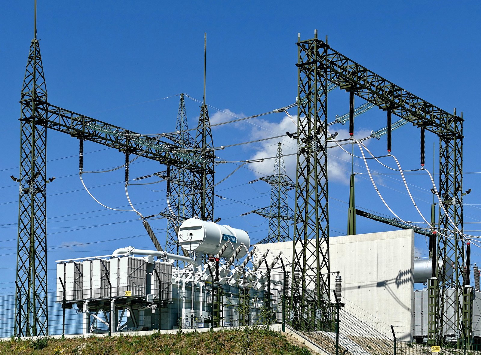
1. What Is a Step-Up Transformer?
A step-up transformer is a static electrical device designed to increase AC voltage from one winding to another. It operates through electromagnetic induction and normally consists of two electrically separate windings placed around a shared magnetic core.
The winding connected to the incoming power supply is called the primary winding. The winding supplying the higher-voltage output is called the secondary winding.
The defining feature is that the secondary winding has more turns than the primary winding. When alternating current flows through the primary winding, it produces a changing magnetic flux in the core. This changing flux links the secondary winding and induces an electromotive force (EMF).
Because the secondary winding has more turns, its induced voltage is higher under the same magnetic-flux conditions.
A step-up transformer does not generate additional energy. Instead, it converts electrical power from a lower-voltage, higher-current condition to a higher-voltage, lower-current condition, subject to losses in the actual equipment.
2. How Does a Step-Up Transformer Work?
The basic operating principle of a step-up transformer is Faraday's law of electromagnetic induction.
When an AC supply is connected to the primary winding, the current changes direction and magnitude periodically. This produces a changing magnetic field, which establishes alternating magnetic flux in the transformer's core.
The core provides a low-reluctance magnetic path that links the primary and secondary windings. As the magnetic flux changes, it induces voltage in both windings.
The process can be understood in four stages:
- AC power enters the primary winding. The alternating current produces a changing magnetic field.
- Magnetic flux travels through the core. The laminated steel core provides a controlled magnetic path.
- Voltage is induced in the secondary winding. The changing flux links the secondary turns and generates an EMF.
- The secondary delivers higher-voltage power. Because it has more turns, its induced voltage is higher than the primary voltage.
The primary and secondary windings are magnetically coupled but are electrically isolated in a conventional two-winding transformer. This distinction is important when comparing a step-up transformer with an autotransformer, which uses a shared winding and does not provide galvanic isolation.
A step-up transformer increases AC voltage because its secondary winding has more turns than its primary winding.True
The induced voltage in a transformer winding is proportional to the number of turns linking the changing magnetic flux, assuming the same core flux and frequency.
3. What Is the Voltage and Turns Ratio of a Step-Up Transformer?
The relationship between primary voltage, secondary voltage, and winding turns is described by the ideal transformer equation:
[\frac{V_s}{V_p}=\frac{N_s}{N_p}]
Where:
- (V_p) = primary winding voltage
- (V_s) = secondary winding voltage
- (N_p) = number of primary winding turns
- (N_s) = number of secondary winding turns
For a step-up transformer:
[\N_s>N_p]
Therefore:
[\V_s>V_p]
Illustrative calculation
Suppose a transformer has:
- Primary voltage: 400 V
- Primary winding turns: 200
- Secondary winding turns: 1,000
The ideal secondary voltage is:
[\V_s=400\times\frac{1000}{200}=2,000\text{ V}]
The transformer therefore increases the voltage from 400 V to approximately 2,000 V under ideal conditions.
| Parameter | Primary side | Secondary side |
|---|---|---|
| Voltage | 400 V | 2,000 V |
| Winding turns | 200 | 1,000 |
| Voltage relationship | Reference | 5 times primary |
| Typical current relationship | Higher | Lower |
| Function | AC input | Higher-voltage output |
Actual output voltage depends on winding resistance, leakage reactance, load current, power factor, and transformer design. The ideal turns ratio is therefore a design relationship, not a guarantee that the measured output voltage will remain exactly constant under every operating condition.
4. How Do Voltage and Current Change in a Step-Up Transformer?
A step-up transformer increases voltage, but current generally decreases when power is transferred through the transformer.
For an ideal transformer:
[\V_p I_p=V_s I_s]
Therefore:
[\I_s=I_p\times\frac{V_p}{V_s}]
Using the previous example, if the primary current is 10 A and the voltage increases from 400 V to 2,000 V:
[\I_s=10\times\frac{400}{2000}=2\text{ A}]
The ideal output is 2,000 V at 2 A, compared with an input of 400 V at 10 A. Both sides transfer approximately 4,000 VA.
In an actual transformer, output apparent power is slightly lower because some energy is lost through winding resistance, core losses, and other internal effects.
This voltage-current relationship explains why step-up transformers are widely used in power transmission. Increasing voltage allows the same approximate power to be transmitted at a lower current, reducing resistive losses in transmission conductors.
5. Why Are Step-Up Transformers Used in Power Systems?
Step-up transformers are essential in power-generation and transmission networks.
Electricity generated by power stations may need to travel long distances before reaching distribution substations and end users. Raising the transmission voltage reduces the current required to transfer a given amount of power.
The resistive power loss in a conductor is:
[\P_{\text{loss}}=I^2R]
Because current is squared in this relationship, reducing current can substantially reduce conductor losses, provided the other conditions remain comparable.
Common applications include:
- Power generation: Increasing generator output voltage to a suitable transmission level.
- Transmission substations: Raising voltage for long-distance electricity transmission.
- Industrial power systems: Supplying higher-voltage equipment and specialized electrical processes.
- Renewable energy installations: Matching generator or inverter output to the required collection or transmission voltage.
- Electrical testing: Producing elevated AC voltages for specific testing applications when the transformer is designed for that duty.
A step-up transformer must always be selected according to the system's voltage, frequency, insulation, load, and protection requirements. A transformer intended for ordinary power transmission should not automatically be assumed suitable for high-voltage testing or other specialized duties.
6. What Are the Main Components of a Step-Up Transformer?
A step-up transformer contains several major components. Their design and quality influence electrical performance, temperature rise, insulation reliability, and service life.
| Component | Main function | Engineering consideration |
|---|---|---|
| Primary winding | Receives AC input power | Rated voltage, current and insulation |
| Secondary winding | Supplies higher-voltage output | Turns ratio, conductor size and insulation level |
| Magnetic core | Provides a path for magnetic flux | Core material, lamination and core losses |
| Insulation system | Separates energized components | Dielectric strength and thermal performance |
| Transformer tank | Houses and protects internal components in oil-immersed designs | Mechanical strength and sealing |
| Cooling system | Removes operating heat | Cooling method and temperature-rise rating |
| Bushings | Provide insulated electrical connections through the enclosure | Voltage class and creepage requirements |
| Protection accessories | Monitor or protect the transformer | Application-specific protection and monitoring design |
Not every step-up transformer uses the same enclosure, cooling arrangement, or accessories. Dry-type and liquid-immersed designs have different construction and installation requirements.
7. What Is the Difference Between a Step-Up and a Step-Down Transformer?
The main difference is their intended voltage conversion direction and winding-turns arrangement.
| Feature | Step-up transformer | Step-down transformer |
|---|---|---|
| Voltage function | Increases voltage | Decreases voltage |
| Secondary turns | More than primary turns | Fewer than primary turns |
| Secondary current | Generally lower | Generally higher |
| Common application | Generation and transmission | Distribution and equipment supply |
| Main purpose | Reduce current for power transfer | Provide a lower voltage for utilization |
Both types operate through electromagnetic induction. Neither creates energy, and both require appropriate ratings for voltage, frequency, apparent power, insulation, cooling, and operating conditions.
8. What Should Buyers Check When Selecting a Step-Up Transformer?
Selecting a step-up transformer requires more than matching the primary and secondary voltage values. Buyers should confirm that the proposed design is compatible with the complete electrical system and the installation environment.
Key selection considerations include:
- Rated primary and secondary voltage: Confirm the required input and output voltage, including system operating range.
- Rated capacity: Select an appropriate kVA or MVA rating based on continuous load, demand profile, and expected future expansion.
- Frequency: Verify compatibility with the supply frequency, such as 50 Hz or 60 Hz. Operating at an unsuitable frequency can affect core flux density and heating.
- Phase configuration: Confirm single-phase or three-phase operation and the required winding connection.
- Percentage impedance: Check its effect on voltage regulation, short-circuit current, and protection coordination.
- Insulation level: Match insulation requirements to the system's maximum voltage and applicable dielectric and impulse withstand requirements.
- Cooling method: Confirm that the cooling arrangement supports the intended loading and environmental conditions.
- Installation environment: Consider indoor or outdoor installation, ambient temperature, altitude, ventilation, dust, moisture, and corrosion exposure.
- Applicable standards and testing: Confirm the relevant IEC 60076 or IEEE C57 requirements, local codes, project specifications, and agreed factory acceptance tests.
Buyers should also review the manufacturer's drawings, nameplate data, test documentation, warranty, and technical support arrangements before placing an order.
How Does a Step-Up Transformer Increase Voltage and Reduce Current?
Transmitting electrical power at relatively low voltage can require high current, increasing resistive losses in cables and creating additional demands on conductors and electrical equipment. If a power system does not use an appropriate voltage-conversion arrangement, energy losses and operating costs can rise, particularly over long transmission distances. A step-up transformer addresses this problem by increasing AC voltage while reducing the current required to transfer approximately the same apparent power. Understanding how this conversion works helps engineers and buyers evaluate transformer ratios, ratings, efficiency, and application suitability.
A step-up transformer increases voltage by using a secondary winding with more turns than its primary winding. Electromagnetic induction produces a higher voltage in the secondary winding, while the current decreases correspondingly under approximately conserved power transfer. This allows electrical power to be transmitted at higher voltage and lower current, reducing resistive losses in transmission conductors.
The relationship between voltage, current, winding turns, and power explains why step-up transformers are essential in electrical transmission networks. The following sections examine the operating mechanism, equations, practical examples, and engineering considerations from a transformer-manufacturing perspective.
1. How Does a Step-Up Transformer Increase Voltage?
A step-up transformer operates through electromagnetic induction. It normally contains two windings—the primary winding and the secondary winding—placed around a shared magnetic core.
When an alternating-current (AC) supply is connected to the primary winding, the changing current produces a changing magnetic field. This establishes alternating magnetic flux in the core, which links the secondary winding and induces an electromotive force (EMF).
The induced voltage depends on the number of turns in each winding. A step-up transformer is designed with more turns on its secondary winding than on its primary winding.
The ideal transformer voltage relationship is:
[\frac{V_s}{V_p}=\frac{N_s}{N_p}]
Where:
- (V_p) = primary voltage
- (V_s) = secondary voltage
- (N_p) = number of primary winding turns
- (N_s) = number of secondary winding turns
Because (N_s) is greater than (N_p), the secondary voltage is higher than the primary voltage.
For example, if a transformer has 200 primary turns and 1,000 secondary turns, its turns ratio is 5:1. With an ideal primary voltage of 400 V, the secondary voltage is:
[\V_s=400\times\frac{1000}{200}=2,000\text{ V}]
The transformer therefore increases the voltage from 400 V to approximately 2,000 V under ideal conditions.
2. Why Does Current Decrease When Voltage Increases?
A transformer does not create additional electrical power. Instead, it changes the relationship between voltage and current.
For an ideal transformer, input apparent power equals output apparent power:
[\V_p I_p=V_s I_s]
Rearranging the equation gives:
[\I_s=I_p\times\frac{V_p}{V_s}]
This means that when voltage increases, current decreases proportionally, assuming the same apparent power is transferred and losses are neglected.
Consider a transformer receiving 400 V at 10 A and increasing the voltage to 2,000 V. Its ideal input and output apparent power are both 4,000 VA.
The secondary current is:
[\I_s=\frac{400\times10}{2000}=2\text{ A}]
The result is a higher-voltage, lower-current output.
\
| Parameter | Primary side | Secondary side |
|---|---|---|
| Voltage | 400 V | 2,000 V |
| Current | 10 A | 2 A |
| Apparent power | 4,000 VA | 4,000 VA |
| Conversion | Reference | 5 times the voltage, one-fifth the current |
The reduction in current is not an independent effect or an optional feature. It follows from the relationship between voltage and power transfer.
3. How Do Winding Turns Control Voltage and Current?
The winding-turns ratio determines the ideal voltage ratio. The current ratio changes in the opposite direction.
For an ideal transformer:
[\frac{I_s}{I_p}=\frac{N_p}{N_s}]
This relationship shows that the secondary current is inversely proportional to the turns ratio.
For example, if the secondary winding has four times as many turns as the primary winding, the ideal secondary voltage is four times higher and the secondary current is approximately one-quarter of the primary current.
The following table illustrates the relationship using an ideal 400 V primary supply and a 10 A primary current.
| Turns ratio (primary) | Secondary voltage | Approximate secondary current |
|---|---|---|
| 1:1 | 400 V | 10 A |
| 1:2 | 800 V | 5 A |
| 1:3 | 1,200 V | 3.33 A |
| 1:4 | 1,600 V | 2.5 A |
| 1:5 | 2,000 V | 2 A |
These are ideal illustrative values. Actual transformer performance depends on load, winding resistance, leakage reactance, core losses, temperature, and design characteristics.
4. How Does a Step-Up Transformer Reduce Transmission Line Losses?
The main reason for increasing voltage in power transmission is to reduce the current needed to deliver a given amount of power.
Electrical conductors have resistance. When current flows through a conductor, some electrical energy is converted into heat. The resistive power loss is calculated using:
[\P_{\text{loss}}=I^2R]
Where:
- (P_{\text{loss}}) = power lost as heat
- (I) = current flowing through the conductor
- (R) = conductor resistance
Because current is squared in this equation, reducing current can significantly reduce resistive losses.
For example, consider transmitting the same apparent power through a line with an assumed resistance of 0.5 Ω.
| Transmission current | Line resistance | Resistive power loss |
|---|---|---|
| 100 A | 0.5 Ω | 5,000 W |
| 50 A | 0.5 Ω | 1,250 W |
| 25 A | 0.5 Ω | 312.5 W |
| 10 A | 0.5 Ω | 50 W |
The comparison shows that reducing current to one-tenth of its original value reduces resistive loss to one-hundredth, provided line resistance remains unchanged.
This is why power stations commonly use step-up transformers before electricity enters high-voltage transmission networks. At the receiving end, step-down transformers reduce voltage to levels suitable for distribution and utilization.
5. Does a Step-Up Transformer Increase Power?
No. A step-up transformer increases voltage, but it does not create additional power.
In an ideal transformer, input and output apparent power are equal:
[\S_p=S_s]
For a single-phase transformer:
[\S=VI]
For a balanced three-phase transformer:
[\S=\sqrt{3}V_{LL}I_L]
Where (V_{LL}) is line-to-line voltage and (I_L) is line current.
In a real transformer, output power is lower than input power because of several types of losses:
- Copper losses: Heat generated by current flowing through winding resistance.
- Core losses: Energy dissipated through hysteresis and eddy currents in the magnetic core.
- Stray losses: Additional losses caused by leakage flux and induced currents in nearby structural components.
- Dielectric losses: Energy dissipated in insulating materials under alternating electrical stress.
Transformer efficiency is commonly expressed as:
[\eta=\frac{P_{\text{out}}}{P_{\text{in}}}\times100%]
Therefore, a practical step-up transformer increases voltage and reduces current while transferring slightly less power than it receives.
6. What Factors Affect Current Reduction in a Real Step-Up Transformer?
Although the turns ratio establishes the ideal voltage and current relationships, actual operating current depends on the connected load and transformer characteristics.
Important factors include:
Load demand: A higher load generally requires more secondary current. The transformer must have sufficient rated capacity to supply the expected load without excessive temperature rise.
Power factor: For AC systems, apparent power depends on voltage and current, while real power also depends on power factor. A low power factor can require higher current to deliver the same real power.
Winding resistance: Resistance in the primary and secondary windings produces copper losses and voltage drops under load.
Leakage reactance and impedance: These affect voltage regulation and the transformer's response to load changes and short-circuit conditions.
Operating temperature: Higher winding temperature increases conductor resistance and can influence losses and available loading capability.
Cooling performance: The cooling arrangement must remove the heat generated by core and winding losses under the specified operating conditions.
A step-up transformer should therefore be evaluated using its rated capacity, voltage ratio, impedance, temperature-rise limits, insulation system, and cooling designation—not simply its turns ratio.
7. What Should Buyers Check When Selecting a Step-Up Transformer?
For manufacturers, engineering contractors, and equipment buyers, selecting the correct step-up transformer requires reviewing the entire electrical application.
| Selection parameter | What to verify | Why it matters |
|---|---|---|
| Primary voltage | Rated input voltage and operating range | Ensures compatibility with the power source |
| Secondary voltage | Required output voltage | Establishes the voltage increase |
| Rated capacity | kVA or MVA | Determines the available loading capability |
| Frequency | 50 Hz or 60 Hz | Affects magnetic flux and core design |
| Phase configuration | Single-phase or three-phase | Matches the electrical system |
| Percentage impedance | Required impedance and tolerance | Influences voltage regulation and fault current |
| Insulation level | System voltage and dielectric withstand requirements | Supports electrical safety |
| Cooling method | Dry-type or liquid-immersed cooling arrangement | Controls operating temperature |
| Applicable standards | Relevant IEC, IEEE and local requirements | Supports project and regulatory compliance |
Buyers should also request technical drawings, nameplate information, routine test reports, and any required design or type-test documentation. The transformer should be selected according to the actual system conditions and project specifications.
Where Is a Step-Up Transformer Used in Power Generation and Transmission Systems?
Electricity generated at a power station must often travel long distances before reaching homes, commercial buildings, and industrial facilities. Transmitting large amounts of power at relatively low voltage requires higher current, which can cause substantial heat losses in conductors, increase voltage drop, and raise infrastructure costs. Without appropriate voltage transformation, delivering electricity efficiently across a large power network becomes more difficult. Step-up transformers solve this problem by increasing voltage at the generation end of the power system, allowing electricity to be transmitted at lower current and with reduced resistive losses.
Step-up transformers are primarily used at power plants and generation substations to increase generator output voltage to a higher transmission voltage. They are also installed in renewable-energy collection systems and other grid-interconnection facilities where voltage must be raised to match the next network level. By increasing voltage and reducing current for approximately the same power transfer, they help minimize transmission-line losses and support efficient power delivery.
To understand where these transformers fit into an electrical network, it is helpful to follow electricity from the generator through the transmission system and toward the distribution network. This article explains their main installation locations, typical applications, operating benefits, and the engineering factors that determine their selection.

1. Why Are Step-Up Transformers Installed at Power Plants?
The most important application of a step-up transformer is at the generation end of an electrical power system.
Generators produce electricity at a voltage determined by their design, insulation system, output capacity, and operating conditions. This generator-terminal voltage is not necessarily suitable for long-distance transmission. A generator step-up transformer (GSU) raises the voltage to the level required by the transmission network.
The main reasons for using a GSU include:
- Reducing current for a given power transfer.
- Lowering resistive losses in transmission conductors.
- Limiting voltage drop along transmission lines.
- Supporting economical transmission over long distances.
- Matching generator output to the transmission-system voltage.
The relationship between three-phase apparent power, line voltage, and line current is:
[\S=\sqrt{3}V_{LL}I_L]
Where:
- (S) = three-phase apparent power
- (V_{LL}) = line-to-line voltage
- (I_L) = line current
For approximately constant apparent power, increasing transmission voltage reduces the current required.
2. Where Is a Step-Up Transformer Located in a Conventional Power Plant?
In a conventional power station, the step-up transformer is generally installed between the generator terminals and the high-voltage transmission switchyard.
The typical power flow is:
- A turbine drives the generator.
- The generator produces three-phase AC electricity.
- The generator output is connected to the primary side of the GSU transformer.
- The transformer raises the voltage.
- The higher-voltage output passes through the switchyard and associated protection equipment.
- Electricity enters the transmission network.
/
The exact arrangement varies by power-station design. Some facilities use a generator breaker between the generator and transformer, while others use different switching and protection configurations.
A GSU transformer must be designed for the generator's rated output, voltage, current, frequency, grounding arrangement, and expected operating conditions. It must also withstand the electrical and mechanical stresses associated with system faults and switching events.
3. How Is a Step-Up Transformer Used in High-Voltage Transmission Substations?
Step-up transformers are also used at generation substations and grid-interconnection facilities to connect one voltage level to a higher-voltage network.
A power system may contain several voltage levels. A generating facility might produce electricity at one voltage, while the regional transmission network operates at a much higher voltage. A transformer provides the necessary interface.
Typical substation functions include:
- Connecting generating units to transmission circuits.
- Raising voltage before electricity enters long-distance lines.
- Connecting different sections of a transmission network.
- Supporting grid expansion and additional generation capacity.
- Providing an interface between renewable-energy facilities and the utility network.
It is important to distinguish a step-up transformer from a transformer used at a transmission substation to connect two existing voltage levels. The latter may be designed for either step-up or step-down operation, depending on the direction of power flow and system configuration.
4. Where Are Step-Up Transformers Used in Renewable-Energy Systems?
Renewable-energy facilities commonly require transformers to connect their electrical output to collection networks and utility transmission systems.
Solar power plants
Solar photovoltaic modules generate DC electricity. Inverters convert this electricity into AC before it is supplied to the plant's collection system. Step-up transformers then raise the AC voltage to the level required by the collector network or grid interconnection.
Depending on the project, transformers may be installed in individual inverter stations, packaged power-conversion units, central substations, or the main grid-interconnection substation.
Wind farms
Wind turbines generate electrical power through generator systems and associated power-conversion equipment. A turbine transformer commonly raises the voltage for collection through the wind farm's medium-voltage network.
The collected power may then pass through a main substation transformer before entering the utility transmission network.
Battery energy storage systems
Battery storage systems use power-conversion equipment to exchange energy between batteries and the AC grid. Transformers may be used to raise or lower voltage depending on the converter output and the connection point.
The appropriate transformer arrangement depends on whether the system is charging, discharging, or providing grid-support services.
/
| Renewable application | Transformer location | Main function |
|---|---|---|
| Solar power plant | Inverter station or central substation | Raises inverter AC output to collection or grid voltage |
| Wind farm | Turbine or wind-farm substation | Raises generator or converter output voltage |
| Battery storage | Power-conversion system or grid interconnection | Matches converter voltage to the connected network |
| Hydropower | Generator substation | Raises generator output voltage for transmission |
Not every renewable-energy transformer is a step-up transformer. The required direction of voltage conversion depends on the equipment's output voltage and the voltage of the network to which it connects.
5. How Does a Step-Up Transformer Reduce Transmission Losses?
The primary technical benefit of raising voltage is reducing the current required to transmit a given amount of power.
Conductor losses are commonly estimated using:
[\P_{\text{loss}}=I^2R]
Where:
- (P_{\text{loss}}) = resistive power loss
- (I) = conductor current
- (R) = conductor resistance
Because current is squared, a reduction in current can significantly reduce resistive losses.
Illustrative example
Assume the same apparent power is transmitted through conductors with a resistance of 0.5 Ω per phase. Compare two operating conditions:
| Parameter | Lower-voltage case | Higher-voltage case |
|---|---|---|
| Three-phase apparent power | 100 MVA | 100 MVA |
| Line-to-line voltage | 33 kV | 132 kV |
| Approximate line current | 1,750 A | 437 A |
| Conductor resistance per phase | 0.5 Ω | 0.5 Ω |
| Three-phase resistive loss | Approximately 4.59 MW | Approximately 0.287 MW |
The higher-voltage case requires approximately one-quarter of the current and produces approximately one-sixteenth of the resistive loss under these simplified assumptions.
Actual transmission losses depend on conductor design, line length, temperature, power factor, reactive power, and network configuration. The calculation illustrates the principle rather than predicting the performance of a specific transmission line.
6. What Is the Difference Between a Step-Up Transformer and a Step-Down Transformer in the Power Network?
Step-up and step-down transformers perform complementary functions.
A step-up transformer raises voltage near the generation source. A step-down transformer reduces voltage at transmission or distribution substations so that electricity can be delivered through progressively lower-voltage networks.
/
| Feature | Step-up transformer | Step-down transformer |
|---|---|---|
| Main function | Increases voltage | Decreases voltage |
| Typical location | Power plant or generation substation | Transmission or distribution substation |
| Secondary turns | More than primary turns | Fewer than primary turns |
| Current relationship | Secondary current generally decreases | Secondary current generally increases |
| Main system purpose | Efficient high-voltage transmission | Voltage adaptation for distribution and utilization |
A transformer does not inherently determine the direction of power flow. Its step-up or step-down designation describes its designed voltage relationship for the specified operating direction.
7. What Technical Requirements Matter When Selecting a Power-Generation or Transmission Step-Up Transformer?
A step-up transformer used in a power plant or transmission system must be selected according to the electrical network and the installation environment.
Important requirements include:
Rated capacity: The kVA or MVA rating must accommodate the expected generator output or network load, including the specified operating conditions and any required overload capability.
Voltage ratio: Confirm the generator-side rated voltage and the transmission-side voltage. For three-phase systems, ensure that the specified voltage ratio accounts for winding connections and whether the values refer to phase voltage or line-to-line voltage.
Frequency: The transformer must match the system frequency. Core flux density depends on voltage, frequency, and winding turns, so operating at a lower frequency without an appropriate design adjustment can increase magnetic flux density.
Percentage impedance: Impedance affects voltage regulation and short-circuit current. It must be coordinated with the generator, transmission system, and protection scheme.
Insulation level: Confirm that the insulation system and dielectric withstand ratings are suitable for the maximum system voltage and the specified switching and lightning impulse requirements.
Cooling method: The selected cooling arrangement must handle expected losses, ambient temperature, loading profile, and installation conditions. Cooling designations such as ONAN and ONAF should be verified against the manufacturer's rated cooling stages.
Protection and monitoring: Consider differential protection, overcurrent protection, temperature monitoring, pressure-relief arrangements, and other accessories required by the project.
Applicable standards: Review the relevant IEC 60076 or IEEE C57 requirements, local regulations, and project-specific technical specifications. The exact applicable standard and edition should be confirmed for the project.
| Engineering requirement | Information buyers should request |
|---|---|
| Electrical ratings | Primary and secondary voltage, frequency, phase and MVA |
| Winding design | Connection, vector group, turns ratio and tap arrangement |
| Fault performance | Percentage impedance and short-circuit withstand capability |
| Insulation | Rated insulation level and dielectric test requirements |
| Thermal performance | Cooling designation and temperature-rise limits |
| Quality assurance | Routine test reports and agreed additional tests |
| Installation | Dimensions, weight, clearances, connections and site requirements |
What Are the Main Components and Technical Specifications of a Step-Up Transformer?
A step-up transformer may look like a single piece of electrical equipment, but its performance depends on several interconnected components and carefully coordinated technical specifications. An unsuitable winding design, inadequate insulation, incorrect impedance, or insufficient cooling capacity can lead to excessive temperature rise, poor voltage regulation, premature insulation deterioration, or unexpected outages. For engineers and equipment buyers, understanding the transformer's construction and nameplate data is essential before selecting a unit for a power-generation, transmission, or industrial application.
The main components of a step-up transformer include the primary winding, secondary winding, magnetic core, insulation system, bushings, enclosure or tank, cooling equipment, and protection accessories. Its key technical specifications include rated capacity (kVA or MVA), primary and secondary voltages, frequency, phase configuration, winding connections, voltage ratio, percentage impedance, insulation level, temperature-rise limits, cooling designation, and applicable standards.
These components work together to transfer electrical energy through electromagnetic induction while maintaining the required voltage, current, insulation, and thermal performance. The sections below explain their functions and show how to interpret the technical specifications when evaluating a step-up transformer.
1. What Are the Main Components of a Step-Up Transformer?
A step-up transformer generally consists of two windings coupled through a magnetic core. Additional components provide insulation, cooling, mechanical protection, electrical connections, and operational monitoring.
The exact construction depends on the transformer type. Oil-immersed power transformers and dry-type transformers, for example, use different insulation, cooling, and enclosure arrangements.
1.1 Primary winding
The primary winding receives AC electrical power from the generator or upstream electrical system. Its alternating current creates a changing magnetic flux in the core.
In a step-up transformer, the primary winding normally has fewer turns than the secondary winding. Its conductor size is selected according to the rated voltage, current, temperature limits, and winding design.
1.2 Secondary winding
The secondary winding supplies the higher-voltage output. It has more turns than the primary winding, allowing a higher induced voltage under the same changing core-flux conditions.
Because the secondary voltage is higher, its winding insulation must be designed for the corresponding electrical stress. The conductor cross-section is selected according to the expected secondary current and thermal requirements.
1.3 Magnetic core
The magnetic core provides a path for magnetic flux linking the two windings. It is commonly constructed from thin, insulated laminations of electrical steel to reduce eddy-current losses.
Core design affects:
- No-load losses
- Excitation current
- Magnetic flux density
- Noise and vibration
- Overall transformer efficiency
1.4 Insulation system
The insulation system separates energized conductors from each other and from grounded components. It also withstands electrical stress, thermal aging, and mechanical forces.
Depending on the transformer design, insulation may include paper, pressboard, enamel, resin, insulating liquids, or other specified materials.
1.5 Tank, enclosure, and cooling equipment
Oil-immersed transformers use a tank to contain the core, windings, and insulating liquid. Radiators or other heat exchangers remove heat generated during operation.
Dry-type transformers use solid insulation and air-based cooling arrangements, often within an enclosure designed for the installation environment.
1.6 Bushings and electrical connections
Bushings provide insulated paths for conductors passing through the transformer tank or enclosure. Their voltage class, current rating, insulation coordination, and mechanical arrangement must match the transformer and connected system.
1.7 Protection and monitoring accessories
Depending on the design and rating, accessories may include temperature indicators, pressure-relief devices, oil-level indicators, gas-actuated relays, cooling controls, and monitoring sensors.
| Component | Main function | Important design considerations |
|---|---|---|
| Primary winding | Receives AC input | Rated voltage, current and insulation |
| Secondary winding | Supplies higher-voltage output | Turns ratio, conductor size and insulation |
| Magnetic core | Carries magnetic flux | Core material, flux density and losses |
| Insulation system | Separates energized parts | Dielectric strength and thermal aging |
| Tank or enclosure | Protects internal components | Mechanical strength, sealing and environmental protection |
| Cooling system | Removes heat | Cooling capacity and auxiliary equipment |
| Bushings | Provide insulated connections | Voltage class, current rating and creepage distance |
| Protection accessories | Monitor or protect equipment | Project-specific protection requirements |
2. How Do the Windings and Magnetic Core Determine Voltage Ratio?
The voltage ratio of a step-up transformer is primarily determined by the number of turns in its windings.
For an ideal transformer:
[\frac{V_s}{V_p}=\frac{N_s}{N_p}]
Where:
- (V_s) = secondary voltage
- (V_p) = primary voltage
- (N_s) = secondary winding turns
- (N_p) = primary winding turns
For a step-up transformer:
[\N_s>N_p]
Therefore:
[\V_s>V_p]
Illustrative example
Suppose a transformer has a primary voltage of 400 V, 200 primary turns, and 1,000 secondary turns.
[\V_s=400\times\frac{1000}{200}=2,000\text{ V}]
The ideal secondary voltage is 2,000 V.
The magnetic core is equally important because it carries the alternating flux that links both windings. Core dimensions, material, lamination design, and operating flux density influence losses, temperature, and transformer performance.
For three-phase transformers, buyers must also distinguish between winding phase-voltage ratios and system line-to-line voltage ratios. Star and delta connections can introduce a (\sqrt{3}) relationship between phase and line quantities, so the vector group and winding connection must be considered when verifying the rated voltage ratio.
3. What Are the Main Electrical Specifications of a Step-Up Transformer?
Electrical specifications describe the conditions under which the transformer is designed to operate.
3.1 Rated capacity
Transformer capacity is generally expressed in kVA or MVA rather than kW because the transformer must handle apparent power, which depends on voltage and current.
For a single-phase transformer:
[\S=VI]
For a balanced three-phase transformer:
[\S=\sqrt{3}V_{LL}I_L]
The selected capacity must accommodate the expected load profile, operating conditions, and any specified future expansion.
3.2 Primary and secondary rated voltages
The primary voltage is the rated input voltage, while the secondary voltage is the rated output voltage. The secondary voltage is higher in a step-up design.
Buyers should confirm both voltage values and identify whether they are phase-to-neutral or line-to-line ratings.
3.3 Frequency
The rated frequency is usually 50 Hz or 60 Hz, depending on the electrical system.
Frequency is important because the magnetic flux density depends on voltage, frequency, and winding turns. For sinusoidal operation, the approximate relationship is:
[\B_{\max}\propto\frac{V}{fN}]
Operating a transformer at a lower frequency without adjusting voltage or design can increase flux density and create a risk of magnetic saturation and excessive heating.
3.4 Phase configuration and winding connection
A step-up transformer may be single-phase or three-phase. Three-phase transformers may use star-star, delta-delta, star-delta, delta-star, or other specified vector-group arrangements.
The correct connection depends on system grounding, phase displacement, neutral requirements, protection, and compatibility with the connected equipment.
3.5 Percentage impedance
Percentage impedance indicates the voltage, expressed as a percentage of rated voltage, required to circulate rated current when the other winding is short-circuited under the specified test conditions.
It affects voltage regulation and prospective short-circuit current. The required value should be coordinated with upstream and downstream system impedance and protection settings.
4. What Are the Main Thermal and Insulation Specifications?
Thermal and insulation specifications determine whether a step-up transformer can operate safely and reliably under its intended electrical and environmental conditions.
| Specification | What it describes | Why it matters |
|---|---|---|
| Insulation level | Dielectric withstand capability | Helps the transformer withstand operating and transient overvoltages |
| Temperature-rise limits | Permitted winding and liquid temperature rise under specified conditions | Protects insulation and supports expected service life |
| Cooling designation | Method used to remove operating heat | Determines thermal performance and cooling equipment |
| Insulation system | Materials separating energized components | Influences dielectric and thermal durability |
| Ambient temperature | Environmental temperature assumed in the design | Affects available thermal margin |
| Altitude | Installation elevation considered in the design | Can affect cooling and external insulation performance |
Common cooling designations include:
- ONAN: Oil Natural Air Natural
- ONAF: Oil Natural Air Forced
- OFAF: Oil Forced Air Forced
- OFWF: Oil Forced Water Forced
- AN: Air Natural, commonly used for dry-type transformers
- AF: Air Forced, commonly used for dry-type transformers
The appropriate cooling arrangement depends on transformer design, rating, loading profile, ambient conditions, enclosure, and installation environment. Adding external fans to a transformer does not automatically authorize a higher rated capacity. Any additional cooling stage and associated loading capability must be supported by the manufacturer's design and ratings.
5. What Information Is Normally Shown on a Step-Up Transformer Nameplate?
The nameplate provides essential identification and operating information. Buyers and maintenance personnel should check it against the approved drawings and project specifications.
| Nameplate item | Typical information |
|---|---|
| Manufacturer | Company name and manufacturing location |
| Serial number | Unique equipment identification |
| Rated capacity | kVA or MVA |
| Rated voltage | Primary and secondary voltage |
| Rated current | Current for each rated winding |
| Frequency | 50 Hz or 60 Hz |
| Phase | Single-phase or three-phase |
| Winding connection | Connection symbols and vector group |
| Percentage impedance | Rated impedance value |
| Cooling designation | Applicable cooling method |
| Insulation level | Specified dielectric withstand ratings |
| Temperature-rise information | Rated thermal limits |
| Applicable standard | Relevant IEC, IEEE or other specified standard |
A nameplate should not be treated as a substitute for the complete technical data sheet. Additional information, such as tap range, short-circuit withstand capability, losses, sound level, dimensions, weight, and accessory details, may be provided in the manufacturer's documentation.
6. What Tests Help Verify Step-Up Transformer Quality?
Testing confirms whether the manufactured transformer meets the agreed technical requirements.
Common routine tests may include:
- Winding resistance measurement: Checks winding resistance and can help identify connection or manufacturing problems.
- Voltage-ratio measurement: Verifies the transformation ratio at specified tap positions.
- Polarity and vector-group checks: Confirms winding polarity and phase displacement.
- Impedance and load-loss measurement: Evaluates short-circuit impedance and load losses.
- No-load loss and excitation-current measurement: Assesses core-related performance.
- Applied-voltage and induced-voltage tests: Evaluate dielectric withstand capability under specified test conditions.
Additional tests may be required depending on the transformer rating, design, applicable standards, and project specification. Buyers should review the test schedule and acceptance criteria before manufacturing begins.
A transformer with the correct voltage ratio is automatically suitable for every power-generation or transmission application.False
Voltage ratio is only one selection parameter. Capacity, frequency, winding connection, impedance, insulation level, cooling, protection, installation conditions, and applicable standards must also be verified.
7. What Should Buyers Check Before Ordering a Step-Up Transformer?
Before issuing a purchase order, buyers should confirm that the technical specification covers the complete operating application.
A practical checklist includes:
- Primary and secondary rated voltages
- Rated kVA or MVA capacity
- Frequency and phase configuration
- Winding connection and vector group
- Percentage impedance and required tolerance
- Tap range and tap-changer operating method
- Insulation level and dielectric test requirements
- Cooling designation and temperature-rise limits
- No-load and load-loss requirements
- Short-circuit withstand capability
- Protection and monitoring accessories
- Installation environment and enclosure requirements
- Applicable standards and factory acceptance tests
- Dimensions, weight, cable or busbar connections, and maintenance access
Relevant standards may include the IEC 60076 series or IEEE C57 series, depending on the project and jurisdiction. The exact applicable editions, clauses, and local requirements should be confirmed rather than assuming one standard applies to every installation.
What Are the Advantages, Limitations, and Safety Requirements of a Step-Up Transformer?
Step-up transformers are essential in power-generation and transmission systems because they increase voltage and reduce the current needed to transfer electrical power. However, selecting one based only on its voltage ratio can create serious engineering and operational problems. Inadequate insulation, incorrect impedance, insufficient cooling, or unsuitable protection can result in overheating, equipment damage, electrical faults, and safety hazards. Understanding the advantages, limitations, and safety requirements of a step-up transformer helps engineers and buyers select equipment that delivers efficient power transfer without compromising personnel or system reliability.
The main advantages of a step-up transformer are higher transmission voltage, lower current for approximately the same power transfer, reduced resistive line losses, and more economical long-distance electricity transmission. Its limitations include conversion losses, high-voltage insulation requirements, cooling and maintenance demands, installation costs, and the absence of voltage conversion with DC power unless suitable conversion equipment is used. Safe operation requires appropriate insulation coordination, grounding, overcurrent and differential protection, temperature monitoring, clearances, and compliance with applicable electrical standards and site regulations.
The correct selection involves balancing electrical performance, equipment cost, maintenance requirements, and safety. The following sections explain what a step-up transformer does well, where its limitations arise, and which design and installation requirements buyers should verify.
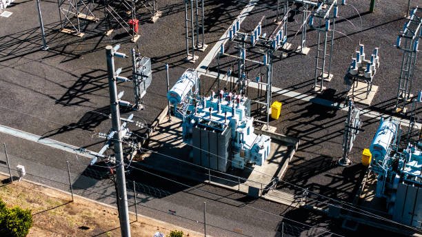
1. What Are the Main Advantages of a Step-Up Transformer?
A step-up transformer increases AC voltage from its primary winding to its secondary winding. Its secondary winding normally has more turns than its primary winding, producing a higher induced voltage through electromagnetic induction.
Its most important advantages are related to power transmission.
1.1 Reduced transmission current
For a given amount of apparent power, increasing voltage reduces the current required.
For a balanced three-phase system:
[\S=\sqrt{3}V_{LL}I_L]
Where:
- (S) = three-phase apparent power
- (V_{LL}) = line-to-line voltage
- (I_L) = line current
When apparent power remains approximately constant, a higher transmission voltage results in lower current.
1.2 Lower resistive power losses
Transmission conductors have electrical resistance. Current flowing through them produces heat, resulting in power loss:
[\P_{\text{loss}}=I^2R]
Because current is squared, reducing current can substantially reduce resistive losses.
For example, if transmission current is reduced to one-half while conductor resistance remains unchanged, resistive power loss falls to one-quarter.
1.3 More economical long-distance transmission
Lower current can reduce the conductor size or the number of parallel conductors required for a given transmission duty, depending on the project's electrical, thermal, mechanical, and regulatory constraints.
This can help control infrastructure costs and improve transmission efficiency.
1.4 Support for large-scale power generation
Generator step-up transformers connect power-station generators to high-voltage transmission networks. They allow electricity generated at a particular terminal voltage to be delivered at the voltage level required by the grid.
They are also used in wind farms, solar power plants, hydropower stations, and other grid-connected generation facilities.
1.5 Flexible system integration
Step-up transformers can be designed for different voltage levels, capacities, winding connections, impedance values, and cooling arrangements. This allows manufacturers to configure equipment for specific generation and transmission requirements.
2. What Are the Limitations of a Step-Up Transformer?
Although step-up transformers offer major benefits, they also introduce design, operational, and installation considerations.
2.1 Electrical and magnetic losses
A step-up transformer does not transfer electrical power without losses. Its main losses include:
- Core losses: Hysteresis and eddy-current losses in the magnetic core.
- Copper losses: Heat generated by current flowing through winding resistance.
- Stray losses: Additional losses caused by leakage flux and induced currents in structural components.
- Dielectric losses: Energy dissipated in insulating materials.
These losses reduce efficiency and contribute to operating temperature.
2.2 High-voltage insulation requirements
The secondary winding operates at a higher voltage, creating greater electrical stress on winding insulation, bushings, clearances, and connected equipment.
The insulation system must be coordinated with the maximum system voltage and the expected switching and lightning overvoltages.
2.3 Cooling and maintenance requirements
Core and winding losses generate heat. Depending on transformer size and design, cooling may require radiators, fans, pumps, heat exchangers, or other thermal-management equipment.
These systems introduce maintenance requirements. Fans, pumps, controls, filters, seals, and insulating liquid condition may need periodic inspection.
2.4 High initial and installation costs
A step-up transformer requires a suitable magnetic core, winding insulation, bushings, protection equipment, and supporting infrastructure. High-voltage installations may also require additional switchgear, surge protection, foundations, clearances, and specialized commissioning procedures.
The total project cost therefore includes more than the transformer purchase price.
2.5 Not suitable for direct DC voltage transformation
A conventional transformer relies on changing magnetic flux to induce voltage in its secondary winding. A steady DC supply does not produce the continuous changing flux required for normal transformer operation.
Power-electronic equipment may be used to convert DC into AC before a transformer is used, or to perform other DC voltage-conversion functions.
| Advantage or limitation | Practical effect | Engineering consideration |
|---|---|---|
| Higher output voltage | Enables high-voltage transmission | Confirm the required voltage ratio |
| Lower transmission current | Reduces conductor losses | Evaluate actual line resistance and load |
| Grid integration | Connects generators to transmission networks | Verify voltage, phase and connection compatibility |
| Electrical losses | Reduces delivered output power | Review guaranteed loss values and efficiency |
| High-voltage insulation | Supports dielectric safety | Confirm insulation coordination |
| Cooling requirements | Controls operating temperature | Verify rated cooling stages and maintenance access |
| Installation costs | Adds infrastructure requirements | Consider total installed and lifecycle costs |
| AC operating principle | Requires changing magnetic flux | Confirm the intended supply type and frequency |
3. How Does a Step-Up Transformer Affect Electrical Safety?
A step-up transformer increases voltage, so its output circuit and connected equipment must be designed for the higher electrical stress.
High voltage creates hazards including electric shock, arc flash, insulation breakdown, and fire. Safe operation therefore requires coordinated design, installation, protection, and maintenance.
3.1 Insulation coordination
The winding insulation, bushings, and external electrical clearances must be appropriate for the maximum system voltage and specified transient overvoltages.
The design should consider:
- Rated insulation level
- Power-frequency withstand voltage
- Lightning impulse withstand requirements
- Switching impulse requirements where applicable
- Creepage and clearance distances
- Environmental pollution and moisture exposure
The required insulation level depends on the system voltage, grounding arrangement, installation environment, and applicable standards.
3.2 Grounding and earthing
Transformer tanks, enclosures, and other exposed conductive parts must be connected to the designated grounding system.
The grounding design should provide a controlled path for fault current and support the operation of protective devices. The grounding arrangement for the transformer windings and system neutral must also match the power-system design.
3.3 Protection against electrical faults
A step-up transformer may be exposed to internal faults, external short circuits, overcurrent, overvoltage, and abnormal operating conditions.
Depending on the transformer and application, protection may include:
- Differential protection
- Overcurrent and earth-fault protection
- Restricted earth-fault protection
- Overvoltage and surge protection
- Temperature and thermal-overload protection
- Pressure-relief devices
- Gas-actuated protection for applicable liquid-immersed designs
Protection settings must be coordinated with generator protection, switchgear, transmission-line protection, and the wider power system.
3.4 Temperature monitoring and cooling supervision
Excessive temperature accelerates insulation aging and can shorten transformer service life.
Appropriate monitoring may include winding-temperature indicators, oil-temperature indicators, cooling-system alarms, and automatic fan or pump controls.
The monitoring and alarm arrangements should reflect the manufacturer's design and project requirements.
4. What Safety Requirements Apply During Step-Up Transformer Installation?
Safe installation requires appropriate site preparation, electrical isolation, mechanical handling, and inspection.
Before installation, the project team should confirm the approved drawings, transformer weight and lifting points, foundation requirements, cable or busbar connections, and required electrical clearances.
Important installation provisions include:
- Foundation and mechanical support: Confirm that the foundation can support the equipment's operating weight and mechanical loads.
- Electrical clearances: Maintain the required distances between energized components, grounded structures, and accessible areas.
- Grounding connections: Install and verify tank, enclosure, and system grounding in accordance with the approved design.
- Cable and busbar connections: Check conductor ratings, termination arrangements, phase identification, and mechanical support.
- Ventilation and cooling: Provide the airflow or cooling infrastructure required by the specified transformer design.
- Fire and environmental protection: For liquid-immersed transformers, assess containment, drainage, fire protection, and environmental requirements.
- Access and working space: Provide suitable access for inspection, testing, and maintenance.
/
Installation work should be performed by qualified personnel under approved procedures. Before maintenance or access, equipment must be isolated, secured against re-energization, and tested to confirm that it is de-energized. Required grounding, discharge, and personal protective equipment procedures must be followed.
5. What Safety Devices Are Commonly Used With Step-Up Transformers?
Transformer safety depends on a coordinated system of protection and monitoring equipment rather than one individual accessory.
| Device or system | Main purpose | Typical application |
|---|---|---|
| Surge arrester | Limits transient overvoltages | High-voltage terminals and connected systems |
| Differential relay | Detects internal electrical faults | Medium- and large-power transformers |
| Overcurrent relay | Detects excessive current | Transformer and feeder protection |
| Temperature indicator | Monitors thermal conditions | Oil-immersed and dry-type designs |
| Pressure-relief device | Releases excessive internal pressure | Applicable liquid-immersed transformers |
| Gas-actuated relay | Detects gas accumulation or oil movement associated with internal faults | Applicable conservator-type transformers |
| Cooling controls | Operate and supervise fans or pumps | Forced-cooling transformer designs |
| Grounding system | Provides a controlled fault-current path | Transformer tank and electrical system |
The exact protection arrangement depends on transformer capacity, construction, voltage level, grounding, and the project's protection philosophy.
6. How Can Buyers Verify That a Step-Up Transformer Meets Safety and Project Requirements?
Buyers should evaluate both the transformer design and the evidence provided by the manufacturer.
A practical verification process includes the following steps:
Confirm electrical ratings. Check rated capacity, primary and secondary voltage, frequency, phase configuration, winding connection, and voltage ratio.
Review impedance and fault performance. Confirm percentage impedance, short-circuit withstand capability, and compatibility with the system's protection coordination.
Verify insulation and thermal performance. Review the specified insulation level, dielectric test requirements, temperature-rise limits, and cooling designation.
Check construction and accessories. Confirm the winding arrangement, core design, bushings, enclosure, cooling equipment, protection accessories, and monitoring provisions.
Review testing and documentation. Request applicable routine test reports, approved drawings, nameplate data, and any additional tests required by the project.
Relevant standards may include the IEC 60076 series or IEEE C57 series, depending on the equipment and jurisdiction. Buyers should identify the applicable editions and project-specific clauses rather than assuming that one standard applies universally.
How Do You Select the Right Step-Up Transformer for Your Application?
Selecting a step-up transformer based only on its input and output voltages can lead to costly engineering mistakes. An undersized transformer may overheat under normal operating loads, while an incorrectly specified impedance, insulation level, or cooling arrangement can compromise system performance and electrical safety. Choosing equipment that does not match the actual application may also result in unnecessary purchase costs, installation difficulties, and premature maintenance. The solution is to evaluate the complete electrical system, including load demand, voltage requirements, operating environment, protection, and future expansion, before finalizing the transformer specification.
To select the right step-up transformer, first determine the required primary and secondary voltages, then calculate the necessary kVA or MVA capacity based on the load profile. Next, verify frequency, phase configuration, winding connections, percentage impedance, insulation level, cooling method, installation conditions, and applicable standards. Finally, compare manufacturer drawings, guaranteed performance data, factory test reports, and lifecycle costs before purchasing.
A systematic selection process helps ensure that a step-up transformer performs reliably under actual operating conditions rather than merely satisfying a nominal voltage ratio. The following guide explains the main selection factors, includes practical calculation examples, and provides a checklist for buyers and project engineers.
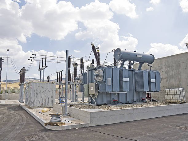
1. Determine the Required Primary and Secondary Voltages
The first step is identifying the voltage available at the transformer's input and the voltage required by the connected electrical system.
The primary winding receives the lower-voltage AC supply, while the secondary winding delivers the higher-voltage output.
For an ideal transformer:
[\frac{V_s}{V_p}=\frac{N_s}{N_p}]
Where:
- (V_p) = primary winding voltage
- (V_s) = secondary winding voltage
- (N_p) = primary winding turns
- (N_s) = secondary winding turns
A step-up transformer has more secondary turns than primary turns.
Example
Suppose an industrial application requires an increase from 400 V to 2,000 V.
[\text{Voltage ratio}=\frac{2000}{400}=5]
The ideal secondary-to-primary turns ratio is therefore 5:1.
This calculation establishes the basic voltage relationship, but the final specification must also account for the three-phase winding connection, voltage tolerance, tap settings, and expected operating conditions.
For three-phase systems, distinguish between phase voltage and line-to-line voltage. Star and delta connections have different relationships between these quantities, so buyers should specify the required system voltage and winding connection clearly.
2. Calculate the Required Transformer Capacity
After determining the voltage ratio, establish the apparent-power rating required by the application.
Transformer capacity is normally expressed in kVA or MVA because the transformer carries voltage and current regardless of the load power factor.
For a single-phase transformer:
[\S=VI]
For a balanced three-phase transformer:
[\S=\sqrt{3}V_{LL}I_L]
Where:
- (S) = apparent power
- (V_{LL}) = line-to-line voltage
- (I_L) = line current
Example: Three-phase application
Assume a three-phase step-up transformer supplies a load requiring 2,000 V at 100 A.
[\S=\sqrt{3}\times2000\times100]
[\S\approx346,410\text{ VA}=346.4\text{ kVA}]
The calculated apparent-power requirement is approximately 346.4 kVA.
The selected rated capacity should then be evaluated against continuous loading, peak demand, load duration, ambient temperature, harmonics, motor starting requirements, and expected expansion. A standard rating above the calculated demand may be appropriate, but the selection should be supported by a load assessment rather than an arbitrary safety margin.
| Application condition | What to evaluate |
|---|---|
| Continuous loading | Long-term average and maximum operating demand |
| Peak loading | Magnitude and duration of temporary peaks |
| Motor loads | Starting current, starting duration and voltage dip |
| Nonlinear loads | Harmonic currents and additional heating |
| Future expansion | Planned additional equipment or generation |
| Ambient conditions | Temperature and altitude at the installation site |
3. Match Frequency and Phase Configuration
Frequency and phase configuration must be compatible with the connected power system.
Frequency
Common power-system frequencies include 50 Hz and 60 Hz. A transformer designed for one frequency should not automatically be assumed suitable for operation at another.
Magnetic flux density is approximately proportional to the ratio of voltage to frequency and winding turns:
[\B_{\max}\propto\frac{V}{fN}]
Operating at a lower frequency without an appropriate voltage or design adjustment can increase core flux density, potentially causing saturation, excessive excitation current, and overheating.
Phase configuration
The transformer may be single-phase or three-phase. Three-phase winding connections include:
- Star-star
- Delta-delta
- Star-delta
- Delta-star
The appropriate arrangement depends on system grounding, neutral requirements, phase displacement, protection coordination, and the connected equipment.
For three-phase projects, buyers should specify the required vector group rather than selecting a winding connection based only on the nominal voltage ratio.
4. Evaluate Percentage Impedance and Short-Circuit Requirements
Transformer percentage impedance is an important specification because it influences voltage regulation and the short-circuit current that can flow through the transformer.
It represents the percentage of rated winding voltage required to circulate rated current during the specified short-circuit impedance test.
A simplified relationship for transformer-terminal symmetrical short-circuit current, assuming negligible upstream source impedance, is:
[\I_{SC}\approx I_{\text{rated}}\times\frac{100}{%Z}]
A lower percentage impedance generally allows higher short-circuit current, while a higher percentage impedance generally limits it.
However, actual fault current also depends on upstream source impedance, cables, system configuration, and fault location.
Buyers should coordinate transformer impedance with:
- Generator or utility source impedance
- Downstream switchgear interrupting ratings
- Protective relay settings
- Cable and busbar withstand capability
- Voltage regulation requirements
- Parallel transformer operating conditions, where applicable
For parallel operation, compatible voltage ratios, polarity, phase sequence, vector groups, and impedance characteristics are essential. Equal percentage impedance alone does not guarantee satisfactory load sharing.
5. Select the Appropriate Insulation Level
A step-up transformer operates with higher secondary voltage, so insulation design is particularly important.
The insulation level must be suitable for the maximum system voltage and the transient overvoltages expected in the installation.
Important considerations include:
- Rated insulation level
- Power-frequency withstand voltage
- Lightning impulse withstand voltage
- Switching impulse withstand requirements, where applicable
- Creepage distance and electrical clearances
- Grounding arrangement
- Pollution, humidity and environmental conditions
The appropriate insulation level depends on the system's maximum voltage, grounding method, installation environment, and applicable standards. Buyers should request the manufacturer's insulation coordination information and relevant dielectric test reports.
6. Choose the Right Cooling Method
Cooling determines how effectively the transformer removes heat generated by core and winding losses.
Common cooling arrangements include:
| Cooling designation | Description | Typical consideration |
|---|---|---|
| ONAN | Oil Natural Air Natural | Natural liquid and air circulation |
| ONAF | Oil Natural Air Forced | Fans increase external heat removal |
| OFAF | Oil Forced Air Forced | Pumps circulate liquid and fans move air |
| OFWF | Oil Forced Water Forced | Liquid circulation through a water-cooled heat exchanger |
| AN | Air Natural | Natural air cooling, commonly for dry-type designs |
| AF | Air Forced | Forced-air cooling, commonly for dry-type designs |
The choice depends on transformer rating, loading profile, ambient temperature, altitude, enclosure, ventilation, maintenance capability, and project fire-safety requirements.
Forced cooling can support a higher manufacturer-rated capacity when the transformer is specifically designed and rated for that cooling stage. Adding fans to an existing transformer does not automatically authorize an increase in its nameplate rating.
7. Consider Installation Environment and Safety Requirements
A transformer suitable for an outdoor power station may not be appropriate for an indoor industrial facility.
Before selecting the enclosure and construction type, assess:
- Indoor or outdoor installation
- Ambient temperature and altitude
- Ventilation and available installation space
- Dust, moisture, salt, and corrosive exposure
- Noise restrictions
- Fire protection and liquid containment requirements
- Foundation loading and lifting access
- Cable or busbar connection arrangements
- Grounding and electrical clearances
- Maintenance access and emergency procedures
Oil-immersed transformers may require containment, drainage, and fire-protection provisions according to the site design and local requirements. Dry-type transformers avoid insulating-liquid containment but are not automatically fireproof or maintenance-free.
8. Compare Efficiency, Losses, and Lifecycle Cost
Purchase price is only one part of the total cost of owning a step-up transformer.
Buyers should review guaranteed no-load losses, load losses, auxiliary cooling power, expected operating hours, maintenance requirements, spare parts, and the cost of potential downtime.
Transformer efficiency is expressed as:
[\eta=\frac{P_{\text{out}}}{P_{\text{in}}}\times100%]
A transformer with a lower purchase price may have higher operating losses, resulting in greater energy costs over its service life.
An appropriate lifecycle assessment should compare:
| Cost factor | Evaluation question |
|---|---|
| Initial purchase | Does the price include required accessories and tests? |
| No-load losses | What energy is consumed whenever the transformer is energized? |
| Load losses | How do losses change with operating current? |
| Cooling auxiliaries | How much electricity do fans and pumps consume? |
| Maintenance | What inspections, servicing and replacement parts are required? |
| Downtime risk | What is the financial impact of an unexpected outage? |
| Service support | Are technical support and spare parts available? |
9. Verify Manufacturer Standards, Testing, and Documentation
Before placing an order, buyers should confirm that the proposed transformer meets the project's technical specification and applicable regulatory requirements.
Relevant standards may include the IEC 60076 series or IEEE C57 series, depending on the application and jurisdiction. The exact applicable editions and clauses should be agreed during technical review.
Request and evaluate:
- Approved technical data sheets
- General arrangement and dimensional drawings
- Nameplate information
- Winding connection and vector-group details
- Guaranteed loss and impedance values
- Insulation and temperature-rise information
- Routine factory test reports
- Required design or type-test documentation
- Installation, operation and maintenance instructions
- Warranty and after-sales service provisions
Routine testing commonly includes winding resistance, voltage ratio, polarity or vector-group verification, impedance and load-loss measurement, no-load loss and excitation-current measurement, and applicable dielectric tests. Additional tests depend on the design, rating, standard, and project requirements.
Step-Up Transformer Selection Checklist
Before finalizing a purchase, confirm the following:
- Primary and secondary rated voltages
- Required kVA or MVA capacity
- Operating frequency
- Single-phase or three-phase configuration
- Winding connections and vector group
- Percentage impedance and tolerance
- Insulation level and dielectric requirements
- Cooling method and rated cooling stages
- Load profile and expected future expansion
- Installation environment and enclosure
- Protection and monitoring accessories
- Guaranteed losses and efficiency requirements
- Applicable standards and factory acceptance tests
- Dimensions, weight, connections and maintenance access
Conclusion
A step-up transformer plays an essential role in modern electrical power systems by increasing voltage and reducing current for efficient power transmission. Its applications range from conventional power plants and renewable energy projects to industrial facilities and transmission substations. Selecting the right unit requires careful evaluation of voltage ratio, rated capacity, insulation, impedance, cooling method, operating environment, and applicable standards.
FAQ
Q1: What is a step-up transformer?
A step-up transformer increases AC voltage from the primary winding to the secondary winding. It has more turns on the secondary side and is commonly used to raise voltage for power transmission.
Q2: How does a step-up transformer work?
It operates through electromagnetic induction. Alternating current in the primary winding creates a changing magnetic field, which induces a higher voltage in the secondary winding when it has more turns.
Q3: Where are step-up transformers commonly used?
They are widely used in power generation stations, transmission networks, solar and wind power systems, industrial facilities, and high-voltage electrical applications.
Q4: What is the difference between a step-up and a step-down transformer?
A step-up transformer increases secondary voltage, while a step-down transformer decreases it. Step-up transformers generally have more secondary winding turns, whereas step-down transformers have fewer.
Q5: How do you choose the right step-up transformer?
Consider input and output voltage, rated capacity, frequency, load characteristics, insulation level, cooling method, impedance, installation conditions, and applicable electrical standards.
References
- IEC 60076-1 — Power Transformers: General
https://webstore.iec.ch/en/publication/588 - IEC 60076-2 — Power Transformers: Temperature Rise
https://webstore.iec.ch/en/publication/604 - IEC 60076-3 — Power Transformers: Insulation Levels and Dielectric Tests
https://webstore.iec.ch/en/publication/605 - IEC 60076-5 — Power Transformers: Ability to Withstand Short Circuit
https://webstore.iec.ch/en/publication/607 - IEEE C57.12.00 — General Requirements for Liquid-Immersed Transformers
https://standards.ieee.org/ieee/C57.12.00/6962/ - IEEE C57.12.90 — Test Code for Liquid-Immersed Transformers
https://standards.ieee.org/ieee/C57.12.90/ - IEEE C57.116 — Transformers Directly Connected to Generators
https://standards.ieee.org/ieee/C57.116/ - IEEE C57.12.80 — Terminology for Power and Distribution Transformers
https://standards.ieee.org/ieee/C57.12.80/7006/ - IEEE Technology Navigator — Power Transformers
https://technav.ieee.org/topic/power-transformers/ - U.S. Department of Energy — Electricity Delivery and Grid Systems
https://www.energy.gov/oe