Transformers play a vital role in electrical power systems by adjusting voltage levels to meet transmission and utilization needs. Among the most common types are step-up and step-down transformers, each serving distinct functions. But what exactly differentiates them, and why are both necessary in modern power networks?
What Is a Step-Up Transformer and How Does It Work?
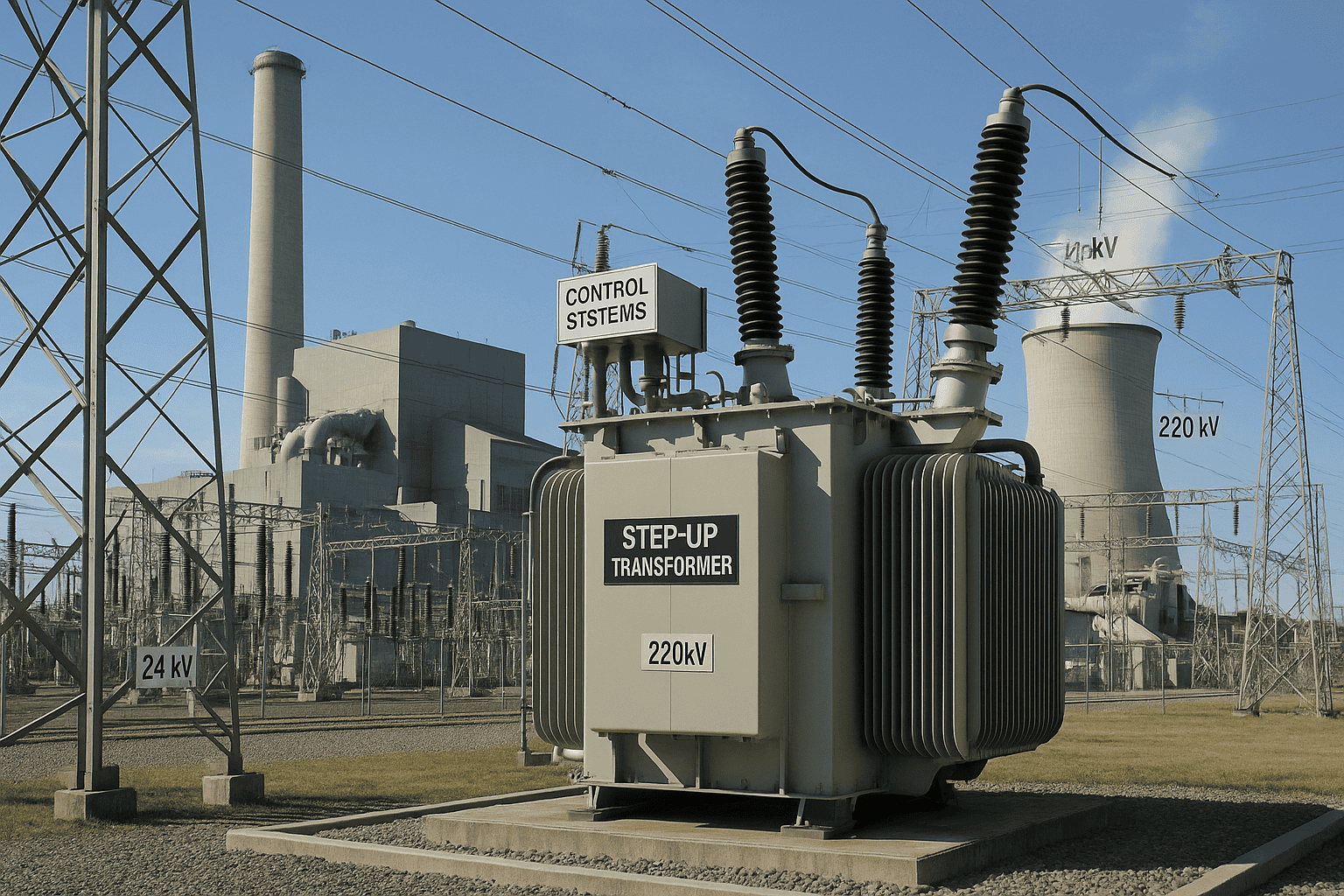
In modern power systems, the transmission of electricity over long distances requires raising voltage levels to minimize energy losses. Without this, enormous amounts of power would be wasted as heat in transmission lines, and infrastructure costs would skyrocket. The problem is that generating stations typically produce electricity at relatively low voltages (11–33 kV), which is not suitable for bulk transmission. The solution to this challenge is the step-up transformer, a critical device that increases voltage levels while reducing current, making long-distance transmission economically and technically viable.
A step-up transformer is an electrical device that increases voltage from a lower level at the primary winding to a higher level at the secondary winding by having more turns of wire in the secondary coil than in the primary coil. It works on the principle of electromagnetic induction: alternating current in the primary winding creates a magnetic flux in the core, which induces a proportionally higher voltage in the secondary winding according to the turns ratio. Step-up transformers are mainly used in power plants to raise generation voltage to transmission levels (e.g., from 11 kV to 220–765 kV), reducing line losses during power delivery.
This makes step-up transformers essential components of efficient power grids and renewable energy integration.
A step-up transformer generates electrical energy.False
Transformers do not generate energy; they only convert voltage levels by electromagnetic induction without changing the total power transferred.
A step-up transformer has more turns in the secondary coil than the primary coil.True
The voltage increase is proportional to the turns ratio (Vs/Vp = Ns/Np), so the secondary winding must have more turns.
1. Basic Principle of Operation
A transformer functions according to Faraday’s Law of Electromagnetic Induction, which states that a changing magnetic flux induces an electromotive force (EMF) in a coil.
- Primary winding: Connected to the source (low voltage, high current).
- Magnetic core: Laminated steel guides magnetic flux with minimal losses.
- Secondary winding: Contains more turns, inducing a higher voltage output.
Formula:
\frac{V_s}{V_p} = \frac{N_s}{N_p}
Where:
- $V_s$ = Secondary voltage
- $V_p$ = Primary voltage
- $N_s$ = Number of secondary turns
- $N_p$ = Number of primary turns
This ensures that if $N_s > N_p$, then $V_s > V_p$.
2. Efficiency Considerations
| Parameter | Impact on Efficiency | Step-Up Transformer Behavior |
|---|---|---|
| Core Losses (hysteresis, eddy current) | Constant regardless of load | Minimized by silicon steel or amorphous core |
| Copper Losses (I²R) | Increases with current | Reduced due to lower current in secondary |
| Load Profile | Determines actual operating efficiency | Peak efficiency at 50–80% loading |
Most modern step-up transformers achieve 98–99.5% efficiency.
3. Real-World Applications
- Power Generation Plants: Raise voltage from 11–33 kV to 220–765 kV for transmission.
- Renewable Energy (Wind/Solar): Convert medium-voltage output (e.g., 690 V in wind turbines) to transmission levels.
- Industrial Processes: Used in furnaces, HV testing, and specific high-voltage equipment.
4. Case Study – Thermal Power Plant
At a 500 MW thermal station:
- Generator output: 21 kV.
- Step-up transformer raises it to 400 kV.
- Transmission losses reduced by over 85% compared to transmitting at generator voltage.
5. Key Advantages
- Reduces transmission line current, minimizing I²R losses.
- Enables smaller conductor sizes, lowering infrastructure cost.
- Improves system stability by standardizing high-voltage transmission.
What Is a Step-Down Transformer and How Does It Work?
The electricity generated and transmitted at high voltage cannot be supplied directly to homes, businesses, or industrial machines, because such levels are unsafe and incompatible with standard electrical equipment. This mismatch between transmission voltages and end-user requirements creates a significant challenge in power systems. Without reducing voltage levels, equipment would be damaged, safety risks would escalate, and power utilization would be inefficient. The solution to this problem lies in the step-down transformer, a critical device that reduces voltage while increasing current to deliver safe and usable electrical energy.
A step-down transformer is an electrical device that decreases voltage from a higher primary level to a lower secondary level by having fewer turns of wire in the secondary coil than in the primary coil. It works on the principle of electromagnetic induction: alternating current in the primary winding produces a magnetic flux in the laminated core, which induces a proportionally lower voltage in the secondary winding according to the turns ratio. Step-down transformers are essential in power distribution, where they reduce transmission voltages (e.g., 220–400 kV) to usable levels (e.g., 230/400 V for households or 11–33 kV for industries).
This function makes step-down transformers the final link in the electricity delivery chain, ensuring power is safe and reliable for all end users.
A step-down transformer increases voltage from the primary to the secondary side.False
A step-down transformer reduces voltage, with the secondary winding having fewer turns than the primary winding.
Step-down transformers are used in power distribution networks to supply electricity to end-users.True
They reduce transmission voltage to levels suitable for residential, commercial, and industrial consumption.
1. Principle of Operation
Step-down transformers obey Faraday’s Law of Electromagnetic Induction: a changing magnetic flux induces an electromotive force (EMF) in a coil.
- Primary winding: Connected to the high-voltage side (fewer amps).
- Core: Provides a path for magnetic flux with minimal losses.
- Secondary winding: Contains fewer turns than the primary, inducing lower voltage but higher current.
Formula:
\frac{V_s}{V_p} = \frac{N_s}{N_p}
Where:
- $V_s$ = Secondary voltage
- $V_p$ = Primary voltage
- $N_s$ = Number of secondary turns
- $N_p$ = Number of primary turns
If $N_s < N_p$, then $V_s < V_p$.
2. Efficiency and Losses
| Type of Loss | Cause | Effect in Step-Down Transformers |
|---|---|---|
| Core Losses (hysteresis, eddy currents) | Constant with voltage | Reduced using high-grade silicon steel or amorphous cores |
| Copper Losses (I²R) | Current flow in windings | More significant on the secondary side (higher current) |
| Stray Losses | Leakage flux and eddy currents | Minimized by compact coil design |
| Dielectric & Cooling Losses | Insulation, oil, or air cooling | Managed with design optimizations |
Typical efficiency: 97–99%, depending on rating and load.
3. Real-World Applications
- Power Distribution: Reduce transmission voltage (132–400 kV) to 11–33 kV, then further to 230/400 V for homes.
- Industrial Systems: Supply medium-voltage machinery, welding equipment, and furnaces.
- Consumer Electronics: Used in adapters and chargers to reduce mains voltage (e.g., 230 V → 12 V).
- Renewables: Step down medium voltage for local microgrids and residential solar inverters.
4. Example – Distribution Transformer in Action
In a city network:
- Transmission line delivers 132 kV.
- Step-down substation transformer reduces it to 33 kV.
- Pole-mounted transformers reduce 33 kV further to 400/230 V.
- Homes, shops, and offices receive safe usable power.
5. Advantages
- Safety: Makes electricity usable for humans and appliances.
- Versatility: From national grids to mobile chargers.
- Reliability: Continuous duty with minimal maintenance.
- Energy Efficiency: Minimizes wastage during voltage conversion.
How Do Voltage and Current Levels Differ Between Step-Up and Step-Down Transformers?
When discussing transformers, one of the most common points of confusion is the relationship between voltage and current. Many end users assume that transformers either “add” or “remove” power, which is not true. Transformers do not create energy; they merely convert voltage and current levels while keeping total power (minus small losses) nearly constant. Failing to understand this balance can lead to incorrect system design, overheating, or equipment failure. The way voltage and current behave differs fundamentally between step-up and step-down transformers, and this distinction is essential for engineers, operators, and consumers alike.
In a step-up transformer, the secondary voltage increases while the current decreases, because the secondary winding has more turns than the primary. In contrast, in a step-down transformer, the secondary voltage decreases while the current increases, since the secondary winding has fewer turns than the primary. In both cases, the power ideally remains the same (P = V × I), apart from minor losses due to resistance and core effects.
Understanding this trade-off ensures correct transformer selection and prevents overloading or energy inefficiencies.
Transformers increase both voltage and current at the same time.False
Transformers trade voltage for current; when voltage increases, current decreases, and vice versa, keeping power nearly constant.
Step-up transformers decrease current while increasing voltage.True
This reduces transmission losses by lowering current in long-distance lines.
1. Voltage and Current Relationship in Transformers
Transformers work on the principle:
\frac{V_s}{V_p} = \frac{N_s}{N_p}, \quad \frac{I_s}{I_p} = \frac{N_p}{N_s}
Where:
- $V_s, V_p$ = Secondary and primary voltages
- $I_s, I_p$ = Secondary and primary currents
- $N_s, N_p$ = Number of turns in secondary and primary windings
Thus:
- Step-Up Transformer: $V_s > V_p$ and $I_s < I_p$
- Step-Down Transformer: $V_s < V_p$ and $I_s > I_p$
2. Comparative Table of Voltage & Current Levels
| Transformer Type | Primary Voltage | Secondary Voltage | Primary Current | Secondary Current | Common Application |
|---|---|---|---|---|---|
| Step-Up | 11–33 kV | 220–765 kV | High | Low | Transmission lines |
| Step-Down | 132–400 kV | 230/400 V | Low | High | Distribution to homes & industries |
3. Example Calculation
Suppose a transformer transmits 10 MW of power.
Step-Up Transformer:
- Input: 11 kV, 909 A.
- Output: 220 kV, 45 A.
Step-Down Transformer:
- Input: 132 kV, 76 A.
- Output: 11 kV, 909 A.
This demonstrates how current decreases as voltage rises, and vice versa, keeping real power nearly the same.
4. Why This Trade-Off Matters
- Transmission Systems: High voltage, low current minimizes I²R losses and allows thinner conductors.
- Distribution Systems: Low voltage, higher current makes electricity safe and compatible with appliances.
- Design Implications: Correct current ratings must be chosen to avoid overheating and ensure insulation safety.
5. Visual Comparison
A step-up transformer “stretches” voltage while “compressing” current, while a step-down transformer does the opposite—compressing voltage while stretching current.
Where Are Step-Up Transformers Commonly Used in Power Systems?
The challenge of modern power delivery lies in transporting electricity over long distances without excessive losses. If electricity generated at a power plant were transmitted directly at low voltages, the currents would be enormous, causing severe I²R losses, thicker conductor requirements, and massive inefficiencies. This is where step-up transformers play a vital role in power systems: they allow electricity to be transmitted at high voltages and low currents, drastically reducing losses and improving grid efficiency. Without them, large-scale centralized power generation and long-distance transmission would not be economically or technically viable.
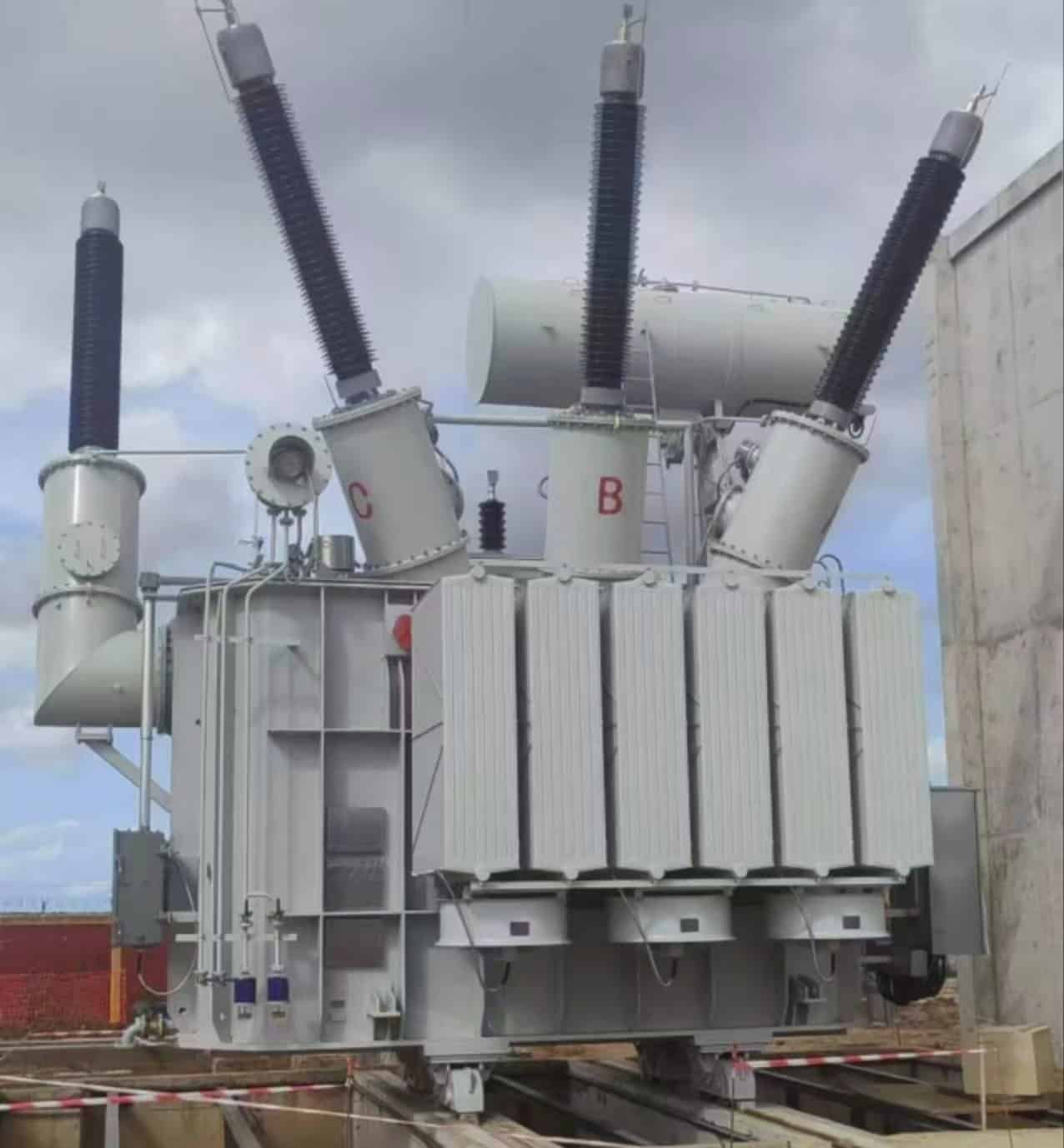
Step-up transformers are most commonly used in power generation stations, renewable energy plants, and HVDC/AC transmission systems, where they raise the generator output voltage (typically 11–33 kV) up to transmission levels (110–765 kV or higher). By increasing voltage and reducing current, they minimize transmission losses, allow thinner conductors, and enable the delivery of electricity across hundreds of kilometers efficiently.
This role makes step-up transformers a critical first link in any modern electrical power system.
Step-up transformers reduce voltage levels for safer residential use.False
Step-up transformers increase voltage for efficient transmission. Step-down transformers reduce voltage for safe consumption.
Step-up transformers are used at power plants to increase generator output voltage before long-distance transmission.True
They boost medium voltage (11–33 kV) to high voltage (110–765 kV), reducing losses.
1. Power Generation Plants
Most generators produce electricity at 11–33 kV. This is too low for transmission efficiency. A step-up transformer located in the power plant substation increases the voltage to 110–765 kV, making it suitable for long-distance transmission via overhead lines.
| Source of Generation | Typical Generator Voltage | Transmission Voltage after Step-Up | Example |
|---|---|---|---|
| Coal/Nuclear Plants | 11–20 kV | 220–400 kV | Centralized grid power |
| Hydropower Stations | 11–33 kV | 132–400 kV | Large dam output |
| Wind Farms | 690 V – 3.3 kV | 33–220 kV | Offshore & onshore wind |
| Solar PV Plants | 600 V – 1.5 kV (DC) | 33–132 kV (after inverter & transformer) | Utility-scale solar farms |
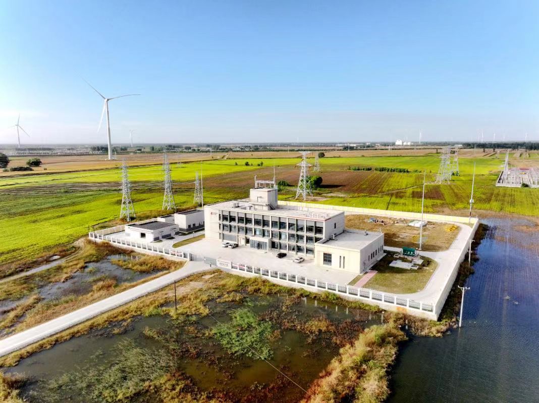
2. Renewable Energy Integration
Step-up transformers are essential for connecting solar farms and wind farms to the grid. Since renewables generate at low or medium voltage, multiple step-up stages may be used:
- Collector step-up transformers at turbines or solar arrays.
- Main step-up transformer at the plant substation to transmission levels.
3. High-Voltage Transmission Systems
- AC Transmission: Boosts voltage to hundreds of kV for nationwide grids.
- HVDC Systems: AC generated at power stations is stepped up, converted to DC, and transmitted at ±500 kV to ±800 kV over thousands of kilometers.
4. Special Applications
- Industrial Plants Exporting Power: Steel plants, refineries, or cogeneration facilities step up internal generation to feed the grid.
- Offshore Platforms: Offshore wind farms and oil rigs use compact step-up transformers to connect long submarine cables.
- Microgrids: Local generators may use smaller step-up units to connect distributed resources efficiently.
5. Why Step-Up Transformers Are Indispensable
- Reduce transmission line losses by lowering current ($P_{loss} = I^2R$).
- Enable long-distance transmission of gigawatts of power.
- Support renewable integration into national grids.
- Ensure economic, safe, and efficient power delivery.
Where Are Step-Down Transformers Commonly Applied in Distribution Networks?
The safe and efficient use of electricity depends not only on generating and transmitting power but also on delivering it at the right voltage level for end-users. High-voltage electricity transmitted over long distances cannot be directly supplied to households, commercial buildings, or factories—it would damage equipment and pose severe safety risks. This is where step-down transformers are indispensable. By gradually reducing transmission voltages to usable distribution levels, they ensure that power is delivered safely, reliably, and efficiently to all categories of consumers.
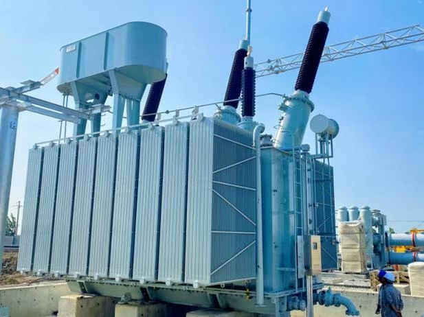
Step-down transformers are most commonly applied in distribution networks at substations, industrial plants, commercial buildings, and residential neighborhoods. They reduce high transmission voltages (132–400 kV) to medium levels (11–33 kV) for distribution and then further step down to low-voltage levels (400/230 V) for safe use in homes, businesses, and equipment.
This layered reduction makes them the final link between the power grid and consumers.
Step-down transformers increase voltage for long-distance transmission.False
Step-down transformers reduce high transmission voltages to safe distribution and utilization levels.
Step-down transformers are used in distribution substations to reduce 132–400 kV transmission levels to 11–33 kV distribution levels.True
This ensures safe delivery of power to industries, businesses, and households.
1. Substation Applications
Step-down transformers are installed in primary substations where transmission lines enter cities or regions. They typically reduce 132–400 kV transmission voltage down to 11–33 kV for distribution along local feeders.
| Transformer Location | Input Voltage | Output Voltage | Application |
|---|---|---|---|
| Primary Substation | 132–400 kV | 11–33 kV | Regional distribution |
| Secondary Substation | 11–33 kV | 400/230 V | Residential and commercial supply |
| Pole-Mounted Units | 11 kV | 400/230 V | Local neighborhood distribution |
2. Industrial Applications
Large industries often require medium-voltage supply (6.6–33 kV) for running heavy machinery. Step-down transformers inside the plant reduce incoming grid voltage to these levels. For internal services like offices, lighting, and IT equipment, additional low-voltage step-down transformers provide 400/230 V.
3. Commercial Applications
- Hospitals, malls, office towers, airports, and data centers use dedicated step-down transformers to ensure stable and safe low-voltage supply.
- Redundancy and backup systems often involve multiple step-down units for reliability.
4. Residential Applications
In neighborhoods, pole-mounted or pad-mounted transformers reduce 11 kV distribution voltage to 400 V three-phase, which is further split into 230 V single-phase for homes. This ensures compatibility with household appliances and safety standards.
5. Renewable and Microgrid Integration
- Solar farms and wind farms may feed into local grids through step-down transformers.
- Microgrids and rural electrification projects rely on compact distribution transformers to deliver usable voltage in remote communities.
6. Importance in the Distribution Chain
Without step-down transformers, it would be impossible to deliver electricity at the correct voltage for diverse users. Their widespread application guarantees:
- Safety: Prevents overvoltage damage to devices.
- Efficiency: Minimizes losses by matching supply voltage with demand.
- Flexibility: Serves different sectors (residential, commercial, industrial).
What Are the Key Differences in Design, Application, and Purpose of Step-Up and Step-Down Transformers?
The global power system relies heavily on transformers, yet their functions differ drastically depending on whether they are step-up or step-down types. This often confuses engineers, industrial buyers, and even students: Why do we need two different categories, and what makes them distinct in design, application, and purpose? Understanding these differences is crucial for choosing the right transformer for any project, whether in power generation, transmission, distribution, or end-user supply.
The key difference is that step-up transformers increase voltage (low to high) to enable long-distance transmission with low losses, while step-down transformers reduce voltage (high to low) to ensure electricity is delivered safely and efficiently to industries, businesses, and households. Their designs differ mainly in winding ratios and insulation, their applications differ across the transmission and distribution chain, and their purposes align with efficiency in transmission versus safety in utilization.
This distinction makes them complementary components, working in sequence to bridge the journey of electricity from the power plant to the consumer.
Step-up and step-down transformers have identical applications in the power grid.False
Step-up transformers are used in generation and transmission, while step-down transformers are applied in distribution and consumption.
The primary purpose of step-up transformers is to reduce transmission losses by raising voltage levels.True
High-voltage transmission reduces current, lowering I²R losses across long distances.
1. Design Differences
The most fundamental design distinction lies in the winding turns ratio and insulation requirements.
| Feature | Step-Up Transformer | Step-Down Transformer |
|---|---|---|
| Winding Ratio | More turns in secondary than primary | More turns in primary than secondary |
| Core Design | Optimized for high voltage withstand | Optimized for low-voltage distribution |
| Insulation | Requires stronger insulation for high-voltage side | Moderate insulation sufficient |
| Size | Larger for high-voltage applications | More compact for local distribution |
| Cooling | Often oil-immersed, forced cooling for large units | Can be oil-immersed or dry-type depending on size |
2. Application Differences
Step-up and step-down transformers are applied at different points in the grid depending on the operational requirement.
| Location in Power System | Step-Up Transformer | Step-Down Transformer |
|---|---|---|
| Power Generation Plants | Raises 11–33 kV generator output to 132–765 kV for transmission | Not used |
| Transmission Substations | Rarely used | Steps down 132–400 kV to 11–33 kV for regional distribution |
| Industrial Facilities | Sometimes used in captive generation export to grid | Reduces 11–33 kV to 400/230 V for equipment and internal supply |
| Renewable Energy Farms | Boosts 690 V – 33 kV up to 132–220 kV for transmission | Reduces incoming medium voltage for local or microgrid distribution |
| Residential/Commercial | Not used | Pole-mounted/pad-mounted units step down 11 kV to 400/230 V |
3. Purpose Differences
The purpose of each type defines its role:
Step-Up Transformer Purpose:
- Boosts generator voltage to reduce current during transmission.
- Minimizes I²R losses in long-distance power delivery.
- Enables economic and efficient use of conductors and infrastructure.
Step-Down Transformer Purpose:
- Reduces voltage for safety and equipment compatibility.
- Provides suitable voltage levels for industries, businesses, and homes.
- Ensures final delivery of electricity to end-users without hazard.
4. Visual Flow of Purpose
Generation (11–33 kV) → [Step-Up Transformer] → Transmission (132–765 kV)
→ [Step-Down Transformer at Substation] → Distribution (11–33 kV)
→ [Step-Down Transformer near Consumers] → Utilization (400/230 V)
Conclusion
Step-up transformers increase voltage to enable efficient long-distance power transmission, while step-down transformers reduce voltage to safe and usable levels for industries, businesses, and homes. Their core difference lies in how they adjust the ratio of primary to secondary windings, affecting both voltage and current flow. Together, they form the backbone of the electrical grid, ensuring power can be transmitted efficiently and utilized safely at the end user’s point of consumption.
FAQ
Q1: What is a step-up transformer?
A step-up transformer increases voltage from the primary side to the secondary side while reducing current proportionally. These are commonly used in power transmission systems to minimize line losses by raising voltage to very high levels (e.g., from 11kV to 220kV or higher).
Q2: What is a step-down transformer?
A step-down transformer decreases voltage from the primary side to the secondary side while increasing current proportionally. They are widely used in power distribution, reducing high transmission voltages (e.g., 11kV or 33kV) to safe, usable levels for homes, offices, and industries (like 415V or 230V).
Q3: What are the structural differences between step-up and step-down transformers?
Step-Up Transformer: Secondary winding has more turns than the primary winding.
Step-Down Transformer: Primary winding has more turns than the secondary winding.
Both types use the same working principle of electromagnetic induction but differ in winding ratio.
Q4: Where are step-up and step-down transformers used?
Step-Up Transformers: Power plants, renewable energy stations, and HVDC transmission.
Step-Down Transformers: Electrical substations, commercial buildings, factories, and residential power supply systems.
Q5: Do step-up and step-down transformers differ in efficiency?
Not significantly—both operate with efficiencies of 95–99%. The difference lies mainly in their application. Efficiency depends more on design, load factor, and core materials rather than whether the transformer is step-up or step-down.
References
IEEE Std C57 – Transformer Definitions and Applications: https://ieeexplore.ieee.org
IEC 60076 – Power Transformer Standards: https://webstore.iec.ch
NEMA – Transformer Types and Applications: https://www.nema.org
Electrical4U – Step-Up vs Step-Down Transformers Explained: https://www.electrical4u.com
EEP – Difference Between Step-Up and Step-Down Transformers: https://electrical-engineering-portal.com
All About Circuits – Transformer Basics: https://www.allaboutcircuits.com
Energy.gov – Transformers in Power Systems: https://www.energy.gov
