Transformer efficiency and performance directly impact energy costs, system reliability, and overall electrical grid stability. Several design, operational, and environmental factors influence how effectively a transformer transfers power while minimizing losses. By understanding these factors, engineers and operators can optimize transformer operation, extend service life, and reduce energy waste.
What Are Core Losses (No-Load Losses) in Transformers?
In every transformer, energy efficiency plays a critical role. One of the unavoidable issues is core loss, also known as no-load loss. These losses occur whenever the transformer is energized, regardless of whether it is delivering load or not. Left unmanaged, core losses lead to constant energy waste, higher electricity bills, and additional heat buildup. Understanding these losses helps operators improve efficiency, reduce operating costs, and select better materials during design.
Core losses in transformers are the power losses that occur in the magnetic core when the transformer is energized without load. They are mainly caused by two phenomena: hysteresis loss (due to magnetization and demagnetization of the core) and eddy current loss (induced circulating currents in the steel laminations). These losses remain nearly constant regardless of load and depend primarily on supply voltage, frequency, and core material quality.
These no-load losses are particularly important for utilities, commercial buildings, and industries with transformers running 24/7, since even small inefficiencies accumulate into significant annual costs.
Core losses vary significantly with transformer load.False
Core losses remain nearly constant once the transformer is energized, as they depend on voltage and frequency rather than load current.
Mechanisms of Core Losses
Core losses arise due to alternating magnetic flux in the transformer core. The two main components are:
Hysteresis Loss
- Occurs when the core material undergoes repeated magnetization and demagnetization cycles.
- Energy is wasted as heat due to molecular friction in the core.
- Depends on supply frequency, maximum flux density, and the hysteresis characteristics of the core steel.
Eddy Current Loss
- Alternating flux induces circulating currents (eddy currents) within the iron core.
- These currents generate resistive heating in the laminations.
- Minimized by using thin, insulated laminations of silicon steel or amorphous alloys.
Factors Influencing Core Losses
| Factor | Effect on Core Losses | Mitigation Strategy |
|---|---|---|
| Supply Voltage | Higher voltage increases flux and losses | Ensure rated voltage operation |
| Frequency | Higher frequency increases hysteresis and eddy losses | Use suitable core materials |
| Core Material | Poor-quality steel increases both loss types | Use silicon steel or amorphous metal |
| Lamination Thickness | Thicker laminations increase eddy currents | Use thinner insulated laminations |
| Flux Density | Higher density increases hysteresis loop area | Design with optimized core flux |
Practical Example
A 1000 kVA distribution transformer with a core loss of 2 kW will waste about:
- 48 kWh/day
- 17,520 kWh/year
- At an energy cost of \$0.10/kWh, this equals \$1,752 annually – even if the transformer carries no load.
What Are Copper Losses (Load Losses) in Transformers?
Every transformer faces unavoidable efficiency losses during operation. While core (no-load) losses occur as soon as the transformer is energized, copper losses—also called load losses—are directly tied to the amount of current drawn by the connected load. Excessive copper losses can lead to overheating, reduced transformer life, and higher energy costs. For users and engineers, understanding load losses is essential for accurate load management, efficiency optimization, and system reliability.
Copper losses (load losses) in transformers are the power losses that occur due to the resistance of the transformer windings when current flows under load conditions. These losses are proportional to the square of the load current (I²R) and increase significantly with higher loading. They manifest as heat in the winding conductors, reducing overall efficiency and limiting transformer capacity.
Because load losses vary with actual transformer utilization, they are a major factor in economic loading decisions, cooling requirements, and operational cost analysis.
Copper losses in transformers remain constant regardless of load.False
Copper losses vary with the square of load current (I²R) and increase as the transformer is loaded.
Mechanisms of Copper (Load) Losses
I²R Losses (Ohmic Resistance Losses)
- Current flowing through windings encounters electrical resistance.
- Losses increase proportionally to the square of the load current.
Formula:
P_{cu} = I^2 \cdot R
where $I$ = load current, $R$ = resistance of winding.
Stray Load Losses
- Additional losses due to leakage flux inducing eddy currents in windings, tank walls, clamps, and structural parts.
- Typically contribute 5–15% of total load losses.
Additional Loss Factors
- Skin Effect: At higher frequencies, current concentrates near the surface of conductors, increasing resistance.
- Proximity Effect: Interaction of magnetic fields between nearby conductors alters current distribution, increasing losses.
Factors Affecting Copper Losses
| Factor | Effect on Copper Losses | Mitigation Strategy |
|---|---|---|
| Load Current (I) | Increases losses with square law | Avoid continuous overloading |
| Winding Resistance (R) | Higher resistance increases losses | Use copper/aluminum of larger cross-section |
| Temperature Rise | Higher temperature increases R | Use forced cooling (ONAF, OFAF) |
| Winding Design | Compact designs reduce leakage reactance and stray losses | Optimize conductor geometry |
| Material Conductivity | Copper has lower resistance than aluminum | Use high-conductivity copper windings |
Practical Example
A 2000 kVA transformer has winding resistance such that copper loss at full load is 15 kW.
At 50% load, losses are:
(0.5)^2 \times 15 = 3.75 \, \text{kW}
At 100% load, losses = 15 kW.
At 125% load, losses =
(1.25)^2 \times 15 = 23.44 \, \text{kW}
This quadratic rise shows why overloading rapidly increases energy waste and heating risk.
Core vs. Copper Loss Comparison
| Parameter | Core Loss (No-Load) | Copper Loss (Load) |
|---|---|---|
| Dependency | Constant, depends on voltage & frequency | Varies with I² (load current) |
| Occurrence | Present at all times | Only under load |
| Typical Share in Total Loss | 20–40% | 60–80% (at full load) |
| Control Method | Better steel, amorphous alloys | Larger conductor size, cooling methods |
What Is Cooling and Temperature Rise in Transformers?
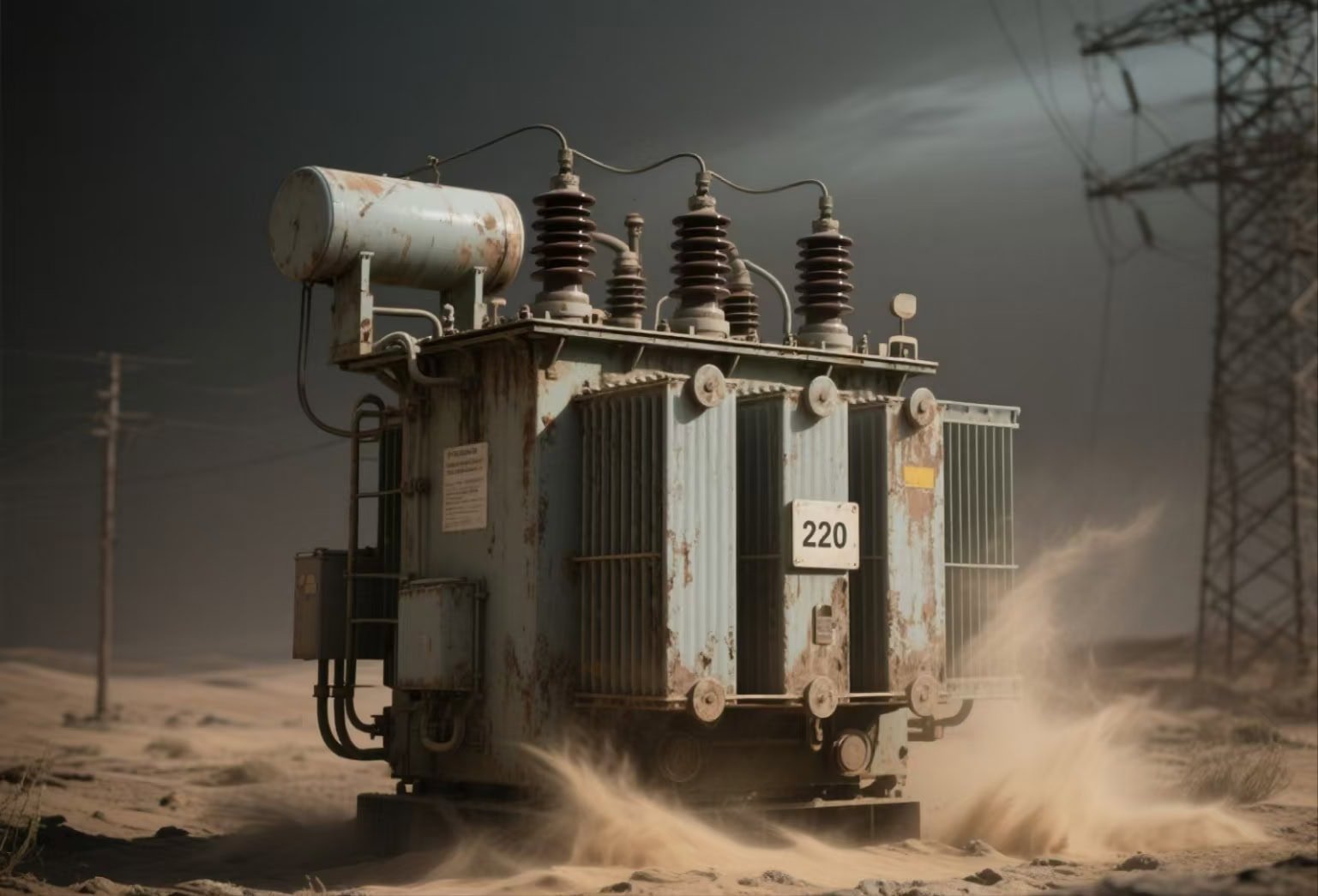
![]()
Transformers operate by converting electrical energy between voltage levels, but in the process, core and copper losses generate heat. If this heat is not dissipated effectively, the winding insulation degrades, efficiency drops, and failure risk rises sharply. Overheating is the most common reason for transformer breakdowns worldwide. The solution lies in proper cooling systems and strict control of temperature rise, which are designed to maintain the transformer within safe thermal limits throughout its service life.
Cooling and temperature rise in transformers refer to the systems and design parameters that manage and limit the heat generated by electrical losses. Cooling methods (like ONAN, ONAF, OFAF, AN, AF) dissipate heat through oil, air, or forced circulation, while “temperature rise” specifies how much hotter the transformer’s windings or oil can become above ambient conditions under rated load. Keeping this rise within standard limits ensures safe operation, extended insulation life, and reliable power delivery.
Because heat accelerates insulation aging, even a 10 °C increase can halve insulation lifespan, making cooling and thermal management central to transformer reliability.
Transformer temperature rise is the difference between winding temperature and oil temperature.False
Temperature rise is defined as the increase of the transformer's winding or oil temperature above the ambient temperature under rated load.
Key Concepts of Cooling and Temperature Rise
Heat Sources in Transformers
- Core losses (hysteresis + eddy currents) → constant heat.
- Copper (I²R) losses → variable heat depending on load.
Cooling Methods
Oil-immersed transformers:
- ONAN (Oil Natural, Air Natural)
- ONAF (Oil Natural, Air Forced with fans)
- OFAF (Oil Forced, Air Forced with pumps + fans)
- OFWF (Oil Forced, Water Forced, for very high ratings).
Dry-type transformers:
- AN (Air Natural, passive cooling)
- AF (Air Forced with blowers).
Temperature Rise
- Defined by IEC/IEEE standards as the maximum allowable rise above ambient temperature (usually 40 °C).
Typical limits:
- Oil: 55–65 °C rise.
- Windings (Class A insulation): 65 °C rise.
- Windings (Class F insulation): 100 °C rise.
Typical Temperature Rise Limits by Insulation Class
| Insulation Class | Max Hot-Spot Temp (°C) | Allowable Temperature Rise (°C) | Expected Life (Years) |
|---|---|---|---|
| Class A (105 °C) | 105 | 55–60 | ~20–25 |
| Class B (130 °C) | 130 | 80 | ~20–25 |
| Class F (155 °C) | 155 | 100 | ~20–25 |
| Class H (180 °C) | 180 | 125 | ~15–20 |
Performance Implications of Cooling & Temperature Rise
- Insulation Aging: Every 6–8 °C above design limit cuts insulation life by 50%.
- Efficiency Loss: High winding resistance due to overheating reduces efficiency.
- Overload Capability: Transformers with effective cooling (OFAF, ONAF) can handle temporary overloads better.
- Size and Cost: Larger cooling systems increase initial cost but improve reliability.
Case Example
A 10 MVA ONAN/ONAF transformer is designed for:
- ONAN mode: 55 °C rise, rated continuous load.
- ONAF mode (with fans): Can handle 40% overload for 4 hours without exceeding 65 °C rise.
This demonstrates how advanced cooling directly enables operational flexibility and extended service under peak demand.
What Is the Relationship Between Power Factor and Load Conditions in Transformers?
Transformers are designed to supply loads within their rated capacity, but how efficiently they deliver this power depends not only on the magnitude of the load but also on the power factor (PF). A low power factor means higher reactive power circulation, leading to increased copper losses, higher current loading, reduced capacity utilization, and potential overheating. This is a common issue in industrial plants where motors, welders, and arc furnaces dominate. The solution lies in power factor correction and careful load management, which improve efficiency, reduce stress on transformers, and lower electricity costs.
Power factor is the ratio of real power (kW) to apparent power (kVA), and it directly affects transformer loading conditions. A transformer supplying a low power factor load must deliver more current for the same useful power, increasing I²R (copper) losses, heating, and voltage drop. High power factor (close to 1.0) means the transformer operates more efficiently, can carry more useful load, and experiences lower losses. Managing load conditions and correcting poor PF with capacitor banks or filters ensures optimal transformer performance and longevity.
Transformers rarely fail from kVA overload alone—it is usually the combination of excessive load and poor PF that accelerates insulation aging and forces premature replacement.
A transformer’s kVA rating changes with power factor.False
The transformer is rated in kVA, which is independent of power factor. However, the useful real power (kW) that can be delivered depends on the power factor of the load.
Understanding the Power Triangle
The relationship between load, power factor, and transformer stress can be explained by the power triangle:
- Real Power (P, kW): Useful work (lighting, heating, mechanical output).
- Reactive Power (Q, kVAR): Required to establish magnetic fields in motors/inductive loads.
- Apparent Power (S, kVA): Vector sum of kW and kVAR, determines transformer loading.
- Power Factor (cos φ): Ratio P/S, representing efficiency of power utilization.
Formula:
\text{Power Factor} = \frac{\text{Real Power (kW)}}{\text{Apparent Power (kVA)}}
Impact of Power Factor on Transformer Load
| Power Factor | Real Power Output (kW) for 1000 kVA Transformer | Current Draw | Transformer Impact |
|---|---|---|---|
| 1.0 (Unity) | 1000 kW | Nominal | Most efficient use of capacity |
| 0.9 (Lag) | 900 kW | ↑ by ~11% | Slightly higher losses |
| 0.8 (Lag) | 800 kW | ↑ by ~25% | Noticeable heating, reduced capacity |
| 0.7 (Lag) | 700 kW | ↑ by ~43% | Significant overheating risk, wasted capacity |
Load Conditions and PF Relationship
- Light Load + Low PF: Even under light load, low PF causes excessive circulating current.
- Full Load + Low PF: Maximum stress, high winding temperature rise, reduced lifespan.
- Balanced Load + High PF: Optimal condition, transformer delivers close to rated efficiency.
- Unbalanced Load: Even with good PF, unequal phase loading stresses windings.
Correcting Power Factor to Improve Transformer Utilization
- Shunt Capacitors: Common for motor-dominated loads.
- Synchronous Condensers: Dynamic PF correction for fluctuating loads.
- Static VAR Compensators (SVC): Advanced systems for arc furnaces or renewable grids.
- Load Management: Avoiding sudden large inductive load switching.
Case Example
A 2000 kVA transformer is supplying an industrial facility:
- At PF = 0.85, it delivers 1700 kW, but current draw is 2350 A.
- After PF correction to 0.98, it delivers 1960 kW with 2040 A current, reducing copper losses by \~15%.
This not only improves transformer life but also reduces electricity billing demand charges.
How Do Design and Material Quality Impact Power Transformer Performance and Reliability?
Power transformers are critical components in modern power systems, transferring electrical energy efficiently from one voltage level to another. When design flaws or poor material quality are present, transformers can suffer from overheating, reduced efficiency, excessive losses, or even catastrophic failure. Such issues result in costly downtime, safety hazards, and frequent replacements. The solution lies in precise engineering design combined with superior material selection to ensure high efficiency, durability, and safety throughout decades of service.
Design and material quality directly determine a power transformer’s efficiency, cooling performance, lifespan, and safety. A well-engineered design ensures optimal magnetic flux, insulation strength, and thermal management, while high-quality materials such as oxygen-free copper, grain-oriented silicon steel, and durable insulation systems reduce energy losses, resist degradation, and extend operational life. Together, they guarantee reliable performance, minimal maintenance, and cost savings over time.
For utilities, manufacturers, and industrial customers, recognizing the interplay of design and material quality is essential when selecting or specifying transformers. Investing in high-quality designs and materials not only reduces total ownership costs but also strengthens grid reliability. Let us now explore the technical foundations of transformer design and materials in detail.
Transformer performance depends only on electrical design and not on material quality.False
Material quality is as important as design. Low-grade steel or copper increases losses, reduces efficiency, and shortens lifespan.
Using high-quality insulation materials in transformers extends service life.True
Superior insulation withstands thermal and electrical stress, delaying aging and preventing premature failures.
Key Factors in Transformer Design
The design of a power transformer involves precise electrical, mechanical, and thermal engineering. Poor design leads to excessive no-load and load losses, weak short-circuit strength, or inefficient cooling. Critical design elements include:
- Core design: The magnetic core must minimize hysteresis and eddy current losses. Grain-oriented silicon steel with step-lap joints improves efficiency.
- Winding configuration: Properly designed windings reduce leakage reactance, improve short-circuit strength, and ensure voltage stability.
- Insulation system: Solid (paper), liquid (mineral oil or ester), and gas insulation must resist breakdown under thermal and electrical stress.
- Cooling system: Forced oil or air cooling ensures long-term temperature stability and minimizes thermal aging.
- Mechanical structure: Tanks, bushings, and tap changers must withstand environmental stresses and mechanical shocks.
Importance of Material Quality
Even the best design cannot perform well if inferior materials are used. Material quality determines transformer losses, mechanical stability, and operational safety. Some examples include:
| Transformer Component | Material Quality Requirement | Effect of Poor Material Choice |
|---|---|---|
| Core | Grain-oriented silicon steel, low hysteresis | High core losses, overheating |
| Windings | Oxygen-free copper / high-grade aluminum | Higher resistance, losses, reduced efficiency |
| Insulation | High dielectric strength cellulose/oil/epoxy | Breakdown, short circuits |
| Cooling Medium | Mineral oil / natural/ester-based fluids | Poor thermal stability, accelerated aging |
| Tank & Structure | High-strength, corrosion-resistant steel | Leaks, mechanical failure |
Comparative Performance Data
Below is a performance comparison of transformers built with different material qualities:
| Specification | Standard Materials | High-Quality Materials |
|---|---|---|
| No-Load Losses (kW) | 2.8 | 1.6 |
| Load Losses (kW) | 15 | 10 |
| Average Service Life (Years) | 15–20 | 30–40 |
| Annual Maintenance Cost (USD) | 8,000 | 3,500 |
| Energy Efficiency (%) | 96% | 99% |
This clearly shows that while high-quality materials may increase initial cost, they drastically reduce lifetime operational costs and failures.
Case Study: Utility-Grade Power Transformers
A large utility in Southeast Asia reported frequent failures of distribution transformers due to insulation breakdown in humid conditions. Investigation revealed the use of low-grade insulation paper with poor moisture resistance. After switching to thermally upgraded paper and ester-based fluids, the average lifespan of transformers increased by 40%, and failure rates dropped by 60%. This case proves how material quality directly translates into grid stability and reduced operational costs.
How Do Environmental and Operating Conditions Influence Power Transformer Performance and Lifespan?
Power transformers are mission-critical assets in power grids, industrial plants, and renewable energy systems. Yet, they rarely operate under ideal laboratory conditions. Instead, they are exposed to harsh environmental and operating factors such as extreme temperatures, humidity, dust, altitude, corrosive atmospheres, overloading, and frequent switching events. Ignoring these conditions can result in insulation breakdown, overheating, accelerated aging, and catastrophic failure. The solution is to carefully evaluate the operating environment during specification, design, and maintenance to ensure reliable and long-term performance.
Environmental and operating conditions significantly affect power transformer reliability by influencing cooling performance, insulation aging, dielectric strength, and mechanical durability. Factors like temperature extremes, moisture, dust, vibration, chemical exposure, altitude, and load fluctuations directly determine service life and maintenance requirements. Designing transformers to withstand these stresses reduces failures, improves efficiency, and extends operational lifespan.
Understanding these variables is critical for utilities, industries, and EPC contractors when selecting transformers. A transformer designed for mild climates may fail quickly in tropical, desert, or high-altitude conditions if the right protective measures are not included.
Environmental factors such as temperature and humidity have little effect on power transformer performance.False
Environmental conditions strongly affect insulation aging, dielectric properties, and cooling efficiency, directly impacting performance.
Operating transformers near rated conditions improves service life.True
Operating close to design limits but avoiding overloading reduces thermal stress and extends insulation life.
Key Environmental Factors Affecting Power Transformers
Environmental stresses directly influence transformer design and maintenance strategies. Below are major factors and their effects:
| Environmental Factor | Effect on Transformers | Example Case |
|---|---|---|
| Ambient Temperature | High temps accelerate insulation aging; low temps reduce oil viscosity | Desert or arctic operations |
| Humidity & Moisture | Ingress leads to insulation breakdown, corrosion, and partial discharges | Tropical climates |
| Dust & Sand | Deposits impair cooling, block breathers, cause overheating | Desert substations |
| Altitude | Reduced air density lowers cooling efficiency and dielectric strength | Mountain installations |
| Pollution & Chemicals | Corrosive gases attack tank, bushings, and gaskets | Industrial zones, coastal areas |
Key Operating Conditions Influencing Transformers
Beyond environment, daily operating stresses also dictate transformer longevity.
| Operating Condition | Effect on Transformers | Example Case |
|---|---|---|
| Overloading | Increases winding temperature, accelerates insulation aging | Peak demand in urban grids |
| Harmonics | Causes additional heating and vibration in core and windings | Industrial plants with nonlinear loads |
| Frequent Switching | Creates transient voltages, mechanical stresses | Renewable energy applications |
| Short-Circuit Stress | Excessive electromechanical forces can deform windings | Transmission-level transformers |
| Oil Contamination | Reduces dielectric strength, promotes overheating | Poorly maintained systems |
Comparative Case Data
Below is a comparison of transformer performance under different operating and environmental stresses:
| Condition | Average Lifespan (Years) | Failure Rate per 100 Units | Mitigation Strategy |
|---|---|---|---|
| Normal Indoor Operation | 35–40 | 3 | Standard maintenance |
| Tropical High Humidity | 20–25 | 12 | Sealed tank, dehumidifiers |
| Desert Dust & Heat | 15–20 | 18 | Enhanced cooling, air filters |
| High Altitude (>2500m) | 18–22 | 15 | Insulation upgrade, derating |
| Overloaded (10% beyond rating) | 10–15 | 20 | Load management, dynamic rating |
Case Study: Coastal Transformers in South Asia
A coastal utility in South Asia experienced frequent transformer oil leaks and premature insulation failure. Investigation revealed that salty, humid air was corroding tank welds and bushings, while moisture ingress degraded oil properties. By switching to stainless steel tanks, hermetically sealed designs, and ester-based insulating fluids, service life increased by 45% and unplanned outages were reduced by half. This case highlights how adapting design to local operating conditions prevents failures.
Conclusion
Transformer efficiency and performance are influenced by a combination of electrical, thermal, material, and environmental factors. Losses in the core and windings, load characteristics, and external conditions all play a role in determining operational effectiveness. By selecting high-quality materials, applying proper cooling methods, and maintaining balanced load conditions, operators can maximize transformer efficiency and extend service life, ultimately lowering operating costs and improving reliability.
FAQ
Q1: What factors mainly affect transformer efficiency?
Transformer efficiency is influenced by core losses (no-load losses), copper losses (load losses), operating load, temperature, harmonics, and power factor. Higher efficiency is achieved by minimizing losses through better design and material selection.
Q2: How does load variation impact transformer performance?
Transformers are most efficient near their rated load (usually 60–80%). Underloading leads to poor efficiency because core losses remain constant, while overloading increases copper losses and causes overheating, reducing lifespan.
Q3: What role does temperature play in transformer efficiency?
High operating temperatures accelerate insulation aging, increase resistance in windings, and reduce efficiency. Cooling systems (oil, dry type AN/AF, ONAN/ONAF) are critical to maintaining safe operating temperatures and performance stability.
Q4: How do harmonics affect transformer performance?
Harmonics from non-linear loads (like VFDs, UPS, or data center equipment) cause additional eddy current and stray losses in transformers. This reduces efficiency, increases heating, and may require derating or special K-rated transformer designs.
Q5: What design and material factors influence transformer efficiency?
Core material: High-grade silicon steel or amorphous metal reduces core losses.
Winding material: Copper windings have lower resistance than aluminum.
Insulation class: Impacts thermal endurance and efficiency under load.
Cooling system: Enhances heat dissipation and performance.
Impedance: Affects voltage regulation and fault current levels.
References
IEEE Std C57 – Transformer Efficiency and Losses: https://ieeexplore.ieee.org
IEC 60076 – Transformer Performance Standards: https://webstore.iec.ch
NEMA – Transformer Efficiency Guidelines: https://www.nema.org
Electrical4U – Transformer Losses and Efficiency: https://www.electrical4u.com
EEP – Factors Affecting Transformer Efficiency: https://electrical-engineering-portal.com
All About Circuits – Transformer Losses Explained: https://www.allaboutcircuits.com
Energy.gov – Transformer Energy Efficiency Standards: https://www.energy.gov
