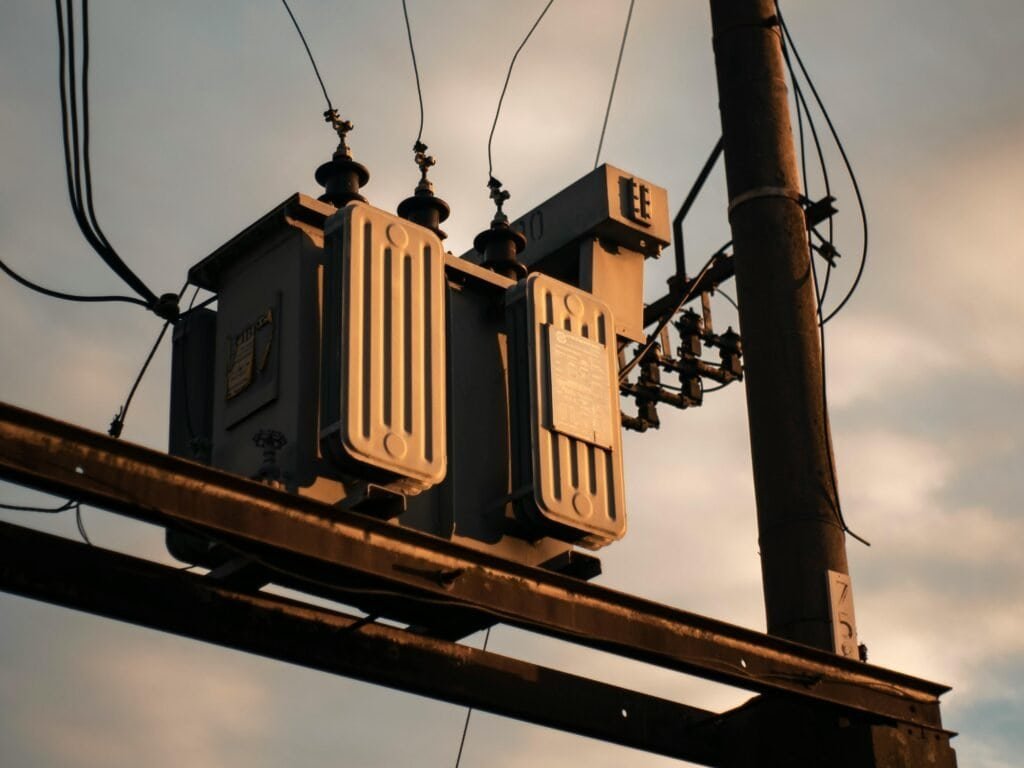
Transformers operate at potentially hazardous voltage and current levels, making electrical safety essential throughout design, manufacturing, installation, operation, maintenance, and decommissioning. Inadequate insulation, improper grounding, insufficient protection, incorrect connections, or poor maintenance can result in electric shock, arc faults, fires, equipment damage, and power-system failures. A comprehensive safety approach is therefore necessary to protect personnel, equipment, and the reliability of the electrical network.
Electrical safety in transformers can be ensured through adequate insulation, correct grounding and bonding, properly coordinated protection devices, appropriate clearances and creepage distances, reliable bushings and connections, effective overload and fault protection, routine inspection and testing, and compliance with applicable electrical standards. Safe operation also requires qualified personnel, appropriate lockout/tagout procedures, suitable protective equipment, and strict installation and maintenance practices.
Transformer safety is not achieved by a single component or test. It depends on the coordination of the transformer design, protection system, installation environment, operating procedures, and maintenance program throughout the equipment lifecycle.
How Can Electrical Safety Be Ensured in Transformers?
Transformer electrical safety is a system-level requirement: a transformer must control insulation stress, prevent unintended contact with energized parts, provide reliable grounding, withstand abnormal voltages and short-circuit forces, and ensure that protection and isolation devices operate correctly. Poor insulation coordination, inadequate clearances, weak grounding, incorrect protection settings, moisture, contamination, or improper commissioning can create electric shock, arc-flash, insulation breakdown, fire, equipment damage, or system-wide outage risks. Electrical safety in transformers is ensured through coordinated insulation design, adequate creepage and clearance distances, effective grounding and bonding, surge protection, appropriate overcurrent and fault protection, safe enclosures and barriers, correct installation, controlled maintenance, and comprehensive electrical testing before and during service.

Transformer electrical safety depends only on the transformer's insulation system.False
Electrical safety also depends on grounding, insulation coordination, clearances, protection, surge control, enclosures, installation, operating procedures and maintenance.
What Are the Main Electrical Safety Risks in Transformers?
A transformer can present several electrical hazards simultaneously.
| Hazard | Possible Consequence | Key Control |
|---|---|---|
| Insulation breakdown | Internal fault or flashover | Insulation system and testing |
| Electric shock | Serious injury or fatality | Grounding, barriers and procedures |
| Arc flash | Burns, pressure and equipment damage | Protection and safe work practices |
| Lightning/switching surge | Insulation failure | Surge protection and coordination |
| Short circuit | High mechanical/electrical stress | Fault protection |
| Poor grounding | Dangerous touch/step voltage | Grounding and bonding |
| Moisture | Reduced insulation performance | Sealing, drying and monitoring |
| Contamination | Surface flashover | Cleanliness and environmental control |
| Incorrect protection | Delayed fault clearing | Relay coordination and testing |
| Backfeed | Unexpected energization | Isolation and verification |
Electrical safety therefore cannot be reduced to a single component.
How Does Transformer Insulation Protect Against Electrical Stress?
Transformer insulation separates conductors operating at different electrical potentials.
Typical insulation components include:
- Paper
- Pressboard
- Insulating varnish
- Resin
- Porcelain
- Composite insulation
- Insulating fluid
The insulation system must withstand normal operating voltage as well as temporary overvoltages and abnormal electrical events.
Electrical stress can result from:
- System voltage
- Lightning
- Switching operations
- Faults
- Resonance
- Uneven voltage distribution
The insulation design must therefore be matched to the transformer's intended application.
Why Are Clearance and Creepage Distances Important?
Clearance is the shortest distance through air between conductive parts.
Creepage distance is the shortest path along an insulating surface.
Both are important for preventing unintended electrical breakdown.
The required values depend on factors such as:
- Operating voltage
- Insulation level
- Environmental conditions
- Pollution
- Altitude
- Insulating material
- Equipment geometry
For outdoor equipment, contamination and moisture can be particularly important because conductive deposits can reduce surface insulation performance.
How Does Insulation Coordination Improve Safety?
Insulation coordination ensures that the transformer's insulation system is selected in relation to expected system overvoltages and protective devices.
A coordinated design considers:
System voltage → expected overvoltage → insulation withstand → surge protection → protective margins
The goal is not simply to make insulation withstand every conceivable voltage. Instead, the electrical system is designed so that abnormal overvoltages are controlled and the equipment has an appropriate withstand margin.
Why Are Surge Arresters Important?
Surge arresters help limit transient overvoltages reaching transformer insulation.
They are particularly important for protection against:
- Lightning impulses
- Switching surges
- Other transient overvoltages
Correct installation matters. An arrester that is incorrectly selected, poorly grounded, or improperly located may not provide the intended protection.
How Does Grounding Improve Transformer Safety?
Grounding provides a controlled electrical path for fault current and helps keep accessible metallic structures at safer potential relationships.
Transformer grounding can involve:
- Tank grounding
- Neutral grounding
- Equipment bonding
- Substation grounding grid
- Cable shields
- Accessory bonding
The grounding system should be designed as part of the overall electrical installation.
The resistance of a conductor is affected by its material resistivity, length and cross-sectional area. In practical grounding systems, however, transformer safety cannot be judged from one resistance number alone; grounding-grid geometry, fault current, soil characteristics and potential gradients also matter.
Why Is Neutral Grounding Important?
The transformer's neutral configuration affects:
- Fault-current magnitude
- Ground-fault protection
- System voltage behavior
- Transient behavior
- Personnel safety
Different systems may use:
- Solid grounding
- Resistance grounding
- Reactance grounding
- Other engineered grounding arrangements
The correct method depends on the electrical network and protection philosophy.
How Can Poor Grounding Create a Safety Hazard?
A damaged or inadequate grounding connection can allow metallic components to rise to dangerous potential during a fault.
Potentially affected components include:
- Transformer tank
- Radiator assemblies
- Cable enclosures
- Control cabinets
- Structural steel
Grounding and bonding connections should therefore be mechanically secure, electrically continuous and periodically inspected.
How Does Overcurrent Protection Improve Safety?
Transformer faults must be detected and cleared rapidly enough to limit damage.
Protection may address:
- Phase faults
- Ground faults
- Overcurrent
- Internal transformer faults
- Thermal abnormalities
- Other abnormal operating conditions
Depending on the transformer and system, protection may include:
- Circuit breakers
- Fuses
- Protective relays
- Differential protection
- Overcurrent protection
- Ground-fault protection
Protection should be coordinated with upstream and downstream equipment.
Why Is Transformer Differential Protection Important?
For many important power transformers, differential protection can detect faults within the protected transformer zone by comparing currents entering and leaving the protected zone.
Under healthy conditions, the measured current relationship is consistent with the transformer's ratio and connection.
For an internal fault, the differential current can become significant, causing the protection system to initiate rapid isolation.
The protection scheme must account for transformer ratio, phase displacement, CT characteristics, tap position and magnetizing inrush behavior.
What Is Transformer Inrush Current?
When a transformer is energized, it can temporarily draw a large magnetizing current known as inrush current.
Inrush can potentially resemble a fault to an improperly designed protection system.
Protection therefore needs suitable discrimination between:
- Energization inrush
- Internal fault current
Incorrect relay settings can cause unwanted trips, while insufficient sensitivity can delay fault clearing.
How Does Short-Circuit Protection Protect the Transformer?
Short circuits can create extremely high electrical currents.
These currents produce electromagnetic forces within windings.
Therefore, short-circuit protection must:
- Detect the fault.
- Operate the appropriate protective device.
- Interrupt the fault current.
- Limit transformer exposure to abnormal electrical and mechanical stress.
The transformer's short-circuit withstand capability and the protection system should be considered together.
Why Is Arc-Flash Safety Important?
Arc flash can occur when electrical insulation or air breaks down between energized conductors or between a conductor and ground.
Potential consequences include:
- Extreme heat
- Pressure
- Molten metal
- Equipment destruction
- Serious injury
Transformer safety programs should therefore consider arc-flash hazards around:
- Bushings
- Switchgear
- Cable terminations
- Disconnects
- Auxiliary equipment
Safe approach distances, appropriate procedures and suitable protective equipment should be established by qualified electrical personnel.
How Can Enclosures and Barriers Improve Safety?
Barriers prevent personnel from unintentionally contacting energized components.
Safety measures may include:
- Locked enclosures
- Physical barriers
- Warning labels
- Restricted-access areas
- Interlocks
- Appropriate fencing
- Grounded metallic structures
Outdoor substations should be arranged so that normal access does not expose personnel to energized parts.
Why Is Moisture a Transformer Electrical-Safety Issue?
Moisture can reduce insulation performance.
It can also promote:
- Corrosion
- Surface contamination
- Tracking
- Electrical leakage
- Insulation aging
For liquid-filled transformers, moisture can migrate between the insulating fluid and solid insulation.
For dry-type transformers, humidity can affect winding and resin insulation surfaces.
Moisture is mainly a mechanical problem and has little effect on transformer electrical safety.False
Moisture can reduce dielectric strength, accelerate insulation aging and contribute to contamination, tracking and electrical breakdown.
How Does Contamination Affect Electrical Safety?
Dust, salt, industrial deposits and other contaminants can accumulate on insulating surfaces.
When combined with moisture, contaminants can become more electrically conductive.
This can increase the possibility of:
- Surface leakage
- Tracking
- Flashover
Environmental exposure should therefore be considered when selecting insulation and maintaining transformer installations.
How Can Partial Discharge Monitoring Help?
Partial discharge represents localized electrical activity within an insulation system.
It can be associated with defects such as:
- Voids
- Delamination
- Sharp electrical stress concentrations
- Contamination
- Insulation deterioration
Where appropriate monitoring or testing is available, partial discharge information can help identify insulation problems before they develop into major failures.
However, partial discharge testing should be interpreted by qualified specialists and according to the applicable transformer test method.
What Electrical Tests Should Be Performed Before Energization?
The commissioning program should be defined according to the transformer type, voltage class and project requirements.
Potential tests include:
| Test | Main Objective |
|---|---|
| Insulation resistance | Evaluate insulation condition |
| Winding resistance | Check winding and connection condition |
| Turns-ratio test | Verify winding ratio |
| Polarity/phase relationship | Verify correct connections |
| Insulation power factor/dissipation factor | Assess insulation condition where applicable |
| Bushing tests | Evaluate bushing insulation where applicable |
| Excitation current | Assess magnetic-circuit behavior |
| Oil tests | Evaluate insulating liquid where applicable |
| Grounding checks | Verify grounding continuity |
| Protection tests | Verify relay and trip functions |
| Functional tests | Verify auxiliary systems |
Test results should be compared with appropriate factory or acceptance data.
Why Should Factory Test Data Be Preserved?
Factory test results provide a baseline.
Later measurements can be compared with the original condition.
This is useful for:
- Commissioning
- Troubleshooting
- Condition monitoring
- Warranty assessment
- Long-term maintenance
Buyers should therefore ensure that relevant factory documentation is retained throughout the transformer's service life.
How Does Correct Installation Affect Electrical Safety?
Even a well-designed transformer can become unsafe through poor installation.
Installation should verify:
- Correct phase connections
- Correct tap position
- Proper grounding
- Appropriate clearances
- Cable termination
- Bushing connections
- Protection wiring
- Auxiliary power
- Control circuits
- Surge-arrester connections
A commissioning checklist should confirm these items before energization.
Why Is Tap-Changer Position Important?
Incorrect tap position can produce an unexpected output voltage.
Before energization, the tap position should match the specified commissioning condition.
For on-load tap changers, control and protection circuits should also be verified.
How Can Buyers Prevent Incorrect Transformer Connections?
Connection errors can result in:
- Incorrect voltage
- Phase displacement problems
- Fault currents
- Protection malfunction
- Equipment damage
Buyers should verify the transformer nameplate, connection diagram and project wiring before energization.
Do not rely solely on cable labeling.
What Role Does Maintenance Play in Electrical Safety?
Electrical safety continues throughout the transformer's service life.
Maintenance can include:
- Grounding inspection
- Bushing inspection
- Insulation testing
- Oil diagnostics
- Protection testing
- Connection inspection
- Thermographic inspection
- Condition monitoring
- Cleaning
- Moisture control
The maintenance frequency should reflect transformer criticality, operating environment and manufacturer recommendations.
How Can Condition Monitoring Improve Electrical Safety?
Monitoring can identify deterioration before a failure occurs.
Useful parameters can include:
- Winding temperature
- Oil temperature
- Moisture
- Dissolved gases
- Partial discharge
- Bushing condition
- Load current
- Voltage
- Tap-changer condition
The purpose is not to collect data for its own sake. Measurements should support decisions such as:
Normal → monitor
Developing abnormality → investigate
Serious deterioration → plan intervention
Critical condition → protect and isolate
What Human-Factor Controls Are Important?
Many transformer incidents are caused or worsened by incorrect procedures.
Important controls include:
- Lockout/tagout
- Permit-to-work systems
- Voltage verification
- Grounding before work
- Restricted access
- Clear switching procedures
- Appropriate PPE
- Qualified personnel
- Communication between operators and maintenance teams
The transformer itself cannot compensate for an unsafe work process.
How Should a Transformer Be Safely Isolated Before Maintenance?
A typical isolation philosophy includes:
Disconnect → lock/tag → verify absence of voltage → discharge stored energy → apply protective grounds where required → establish safe work boundaries
The exact procedure must follow the electrical system, equipment design and applicable safety procedures.
A switch being in the “off” position should never be treated as sufficient proof that equipment is de-energized.
What Are the Most Common Electrical-Safety Mistakes?
Buyers and operators should avoid:
- Inadequate grounding
- Ignoring insulation coordination
- Incorrect surge-arrester selection
- Insufficient clearance
- Poor bushing connections
- Incorrect tap settings
- Incorrect protection settings
- Skipping commissioning tests
- Ignoring moisture
- Allowing contamination to accumulate
- Poor enclosure security
- Working without proper isolation
- Energizing after abnormal test results
- Treating electrical safety as only an equipment-design issue
How Can Buyers Specify Electrical Safety During Procurement?
Electrical safety should be included in the technical specification.
Specify, as applicable:
- System voltage
- Insulation levels
- Impulse withstand requirements
- Insulation system
- Creepage and clearance requirements
- Grounding provisions
- Neutral arrangement
- Surge-protection requirements
- Short-circuit withstand
- Protection interfaces
- Bushing requirements
- Enclosure requirements
- Factory testing
- Routine and type tests
- Commissioning requirements
- Documentation requirements
This gives suppliers a clear technical basis for designing and testing the transformer.
What Should a Buyer Check Before Energization?
A practical final checklist is:
Transformer
- Correct nameplate
- Correct rating
- Correct connection
- Correct tap position
- No visible damage
Insulation
- Appropriate insulation tests completed
- Bushings inspected
- Moisture condition acceptable
- Oil condition acceptable where applicable
Grounding
- Tank grounded
- Neutral grounding correct
- Bonding complete
- Grounding connections secure
Protection
- Protective relays tested
- Trip circuits verified
- Breaker operation confirmed
- Protection settings approved
Surge protection
- Surge arresters installed correctly
- Connections verified
- Ground paths verified
Installation
- Clearances confirmed
- Cable connections checked
- Enclosures secured
- Warning signs installed
- Restricted areas established
Documentation
- Test records complete
- Abnormal findings resolved
- Commissioning approval obtained
Buyer Takeaway
Electrical safety in transformers depends on the coordinated performance of insulation, clearances, grounding, surge protection, fault protection, enclosures, installation practices, testing and operating procedures. Buyers should not evaluate transformer safety from insulation specifications alone. The complete electrical system must control normal voltage, transient overvoltage, fault current, touch potential, insulation deterioration and human access to energized components.
A practical safety chain is:
Insulation design → insulation coordination → grounding → surge protection → fault protection → safe installation → commissioning tests → controlled operation → condition monitoring → maintenance.
For transformer procurement, the most useful question is not simply “Does this transformer have adequate insulation?” but “Can the complete transformer and protection system safely withstand, detect, isolate and manage the electrical stresses expected throughout its service life?”
How Do Insulation Systems Improve Electrical Safety in Transformers?
Transformer insulation is the primary barrier preventing unintended electrical breakdown between windings, between winding layers, and between energized conductors and grounded structures. When insulation is poorly selected, improperly manufactured, contaminated, overheated, or exposed to excessive electrical stress, the result can be partial discharge, surface tracking, internal faults, flashover, fire, or catastrophic transformer failure. A properly engineered transformer insulation system improves electrical safety by separating conductors at different potentials, controlling electric-field stress, providing sufficient dielectric withstand, maintaining insulation integrity under thermal and mechanical stress, and coordinating with clearances, bushings, surge protection, grounding and protection systems. Effective safety therefore depends not only on insulation material, but also on insulation geometry, manufacturing quality, moisture control, temperature management, testing and long-term condition monitoring.

Transformer insulation improves electrical safety primarily by preventing current from flowing between conductors that should remain electrically separated.True
The insulation system provides dielectric separation between conductors at different electrical potentials and helps prevent unintended current paths, flashover and insulation breakdown.
A transformer with high dielectric-strength insulation is automatically safe regardless of moisture, temperature, electric-field concentration and manufacturing quality.False
Transformer insulation performance depends on the complete insulation system, including material condition, geometry, moisture, thermal stress, electric-field distribution, manufacturing quality and operating conditions.
What Is a Transformer Insulation System?
A transformer insulation system is not simply one insulating material. It is an engineered combination of materials and geometry designed to withstand electrical, thermal and mechanical stresses over the transformer's expected service life.
Depending on transformer construction, the system may contain:
- Kraft paper
- Pressboard
- Laminated insulation
- Enamel or varnish
- Epoxy resin
- Cast resin
- Porcelain
- Composite materials
- Insulating liquids
- Air gaps
- Structural insulation
Oil-immersed power transformers commonly use oil-paper insulation systems, in which solid cellulose insulation works together with insulating liquid.
Dry-type transformers instead commonly use combinations of solid insulation, varnish, resin and air.
The safety objective is the same: maintain reliable dielectric separation while managing the electrical, thermal and mechanical stresses imposed on the transformer.
How Does Insulation Prevent Electrical Breakdown?
A transformer contains conductors operating at substantially different electrical potentials.
Without adequate insulation, electrical current could take an unintended path between:
- Adjacent winding turns
- Winding layers
- High- and low-voltage windings
- Windings and core
- Windings and tank
- Conductors and grounded structures
Insulation introduces a high-resistance dielectric barrier between these regions.
However, insulation must withstand more than normal voltage. The design must also consider temporary overvoltages and transient stresses caused by events such as:
- Lightning
- Switching
- Faults
- System disturbances
This is why transformer insulation design must be coordinated with the electrical network.
How Does Insulation Geometry Improve Safety?
Material selection alone does not determine insulation performance.
Geometry strongly influences the local electric field.
Engineers consider:
- Winding spacing
- Insulation thickness
- Layer arrangement
- Inter-turn insulation
- Axial insulation
- Radial insulation
- End insulation
- Shielding
- Grading structures
- Creepage paths
Sharp edges or abrupt changes in geometry can concentrate electrical stress.
A good insulation system distributes electrical stress more uniformly and avoids local regions where the dielectric may be overstressed.
Why Is Electric-Field Control Important?
Dielectric breakdown generally occurs when local electrical stress exceeds what the insulation system can reliably withstand.
Therefore, engineers seek to control:
Voltage → electric-field distribution → local stress → dielectric withstand
The highest voltage does not necessarily correspond to the highest local electrical stress.
Field concentration can occur around:
- Conductive edges
- Winding ends
- Leads
- Connections
- Shielding transitions
- Geometric discontinuities
Insulation design attempts to control these stress concentrations.
What Is Inter-Turn Insulation?
Inter-turn insulation separates adjacent turns of a winding.
This is especially important because a winding contains many turns operating at progressively different electrical potentials.
Inter-turn insulation may use:
- Enamel
- Paper
- Composite materials
- Varnish
- Other approved dielectric systems
A localized failure between turns can create a shorted-turn condition.
That can generate:
- High circulating current
- Localized heating
- Additional insulation deterioration
- Winding damage
Thus, inter-turn insulation is an important part of transformer electrical safety.
How Does Layer Insulation Protect Windings?
Layer insulation separates groups of winding turns or conductor layers.
Its functions include:
- Preventing electrical contact
- Controlling voltage distribution
- Increasing dielectric withstand
- Supporting mechanical construction
- Helping control local electric-field stress
In high-voltage transformer windings, layer insulation must be carefully coordinated with the expected voltage distribution.
Why Is Main Insulation Between Windings Important?
The insulation separating high-voltage and low-voltage windings must withstand the voltage difference between them.
It may include combinations of:
- Oil
- Pressboard cylinders
- Paper
- Spacers
- Barriers
- End insulation
The exact configuration depends on the transformer design.
The insulation must maintain adequate dielectric performance throughout normal operation and during specified transient conditions.
How Does Solid Insulation Work With Insulating Oil?
In an oil-immersed transformer, the liquid and solid insulation work together.
The insulating liquid provides dielectric separation around the winding assembly, while paper and pressboard provide structural and localized insulation.
This creates a combined insulation system.
A simplified concept is:
Conductors → solid insulation → insulating liquid → solid barriers → other conductors
The system must be designed as a whole because moisture and thermal aging can affect both solid and liquid components.
Why Is Moisture Dangerous to Transformer Insulation?
Moisture is one of the most important factors affecting cellulose insulation.
It can:
- Reduce dielectric performance
- Accelerate insulation aging
- Increase the likelihood of partial discharge under unfavorable conditions
- Affect mechanical strength
- Influence moisture distribution between oil and solid insulation
The effect can become particularly important at elevated temperature because moisture distribution between insulating materials can change with temperature.
Keeping transformer insulation dry helps maintain its dielectric and mechanical performance.True
Moisture can adversely affect cellulose-based insulation and accelerate deterioration, so moisture control is an important part of transformer insulation management.
How Does Temperature Affect Insulation Safety?
Transformer insulation experiences thermal stress throughout operation.
Temperature rises when the transformer carries load and when losses occur in:
- Windings
- Core
- Structural components
- Other conductive parts
Excessive temperature can accelerate insulation aging.
This creates an important relationship:
Electrical loading → losses → temperature rise → insulation aging
Insulation design therefore has to be compatible with the transformer's thermal design.
Cooling systems, winding design and temperature monitoring all contribute to maintaining insulation reliability.
Why Is Insulation Aging Important?
Insulation does not remain unchanged throughout the transformer's service life.
Long-term deterioration can result from:
- Heat
- Moisture
- Oxygen
- Electrical stress
- Mechanical stress
- Contamination
- Repeated fault events
As insulation deteriorates, its electrical and mechanical properties may change.
Condition monitoring and maintenance can help identify deterioration before it becomes a major failure.
How Does Partial Discharge Relate to Insulation Safety?
Partial discharge is localized electrical activity that does not completely bridge the insulation system.
It can be associated with defects such as:
- Voids
- Delamination
- Contamination
- Local field concentrations
- Poor interfaces
- Manufacturing defects
Persistent or increasing partial discharge can indicate an insulation problem requiring investigation.
It is therefore an important diagnostic concept in high-voltage transformer insulation.
How Does Insulation Prevent Flashover?
Flashover is an electrical discharge that travels across or through an insulating region.
Adequate insulation systems reduce this risk by maintaining sufficient:
- Dielectric strength
- Clearance
- Creepage
- Surface insulation
- Field-control capability
Outdoor transformers face additional environmental stresses because rain, salt, dust and industrial pollution can contaminate insulating surfaces.
What Is the Difference Between Clearance and Creepage?
Clearance refers to the shortest distance through air between conductive parts.
Creepage refers to the shortest path along an insulating surface.
Both can affect electrical safety.
| Factor | Clearance | Creepage |
|---|---|---|
| Path | Through air | Along insulation surface |
| Main concern | Air breakdown | Surface leakage/tracking |
| Environmental influence | Moderate | Often significant |
| Moisture effect | Important | Potentially severe |
| Pollution effect | Important | Particularly important |
| Typical design focus | Physical separation | Surface path length and condition |
The required values depend on voltage, insulation system, pollution environment, altitude and applicable design requirements.
How Does Pollution Affect Insulation?
Outdoor transformer insulation can accumulate:
- Dust
- Salt
- Industrial deposits
- Chemical contaminants
When moisture is added, these deposits can form a more conductive surface layer.
This may increase:
- Leakage current
- Surface heating
- Tracking risk
- Flashover probability
Therefore, insulation systems for polluted environments may require appropriate creepage design and maintenance strategies.
How Do Transformer Bushings Contribute to Insulation Safety?
Bushings provide an insulated path for conductors passing through grounded transformer structures.
A bushing must maintain dielectric separation between:
Energized conductor ↔ grounded tank
Bushing insulation may use:
- Porcelain
- Resin
- Composite materials
- Oil
- Paper-based condenser structures
Bushing condition is therefore an important part of overall transformer electrical safety.
A transformer can have healthy internal winding insulation while still presenting a serious electrical problem if a bushing is damaged or deteriorated.
How Does Insulation Support Short-Circuit Safety?
Short circuits create high currents and electromagnetic forces.
These forces can deform windings.
Therefore, transformer insulation must also be mechanically supported.
The insulation system can contribute to:
- Winding compression
- Conductor separation
- Mechanical stability
- Resistance to movement during fault events
This demonstrates why transformer insulation is both an electrical and mechanical system.
Why Should Insulation Be Mechanically Supported?
A dielectric material that performs well electrically but cannot maintain its position under mechanical stress is not an adequate transformer insulation system.
During:
- Short circuits
- Transportation
- Installation
- Thermal expansion
- Normal vibration
insulation components may experience mechanical forces.
Designers therefore consider both dielectric and structural requirements.
How Do Dry-Type Transformer Insulation Systems Improve Safety?
Dry-type transformers eliminate the need for liquid insulation.
Their insulation system commonly relies on:
- Resin
- Epoxy
- Varnish
- Solid barriers
- Air
- Encapsulation
A properly designed dry-type insulation system can provide strong electrical separation without insulating-oil leakage.
This can be advantageous in applications where:
- Fire risk must be minimized
- Indoor installation is preferred
- Environmental leakage is a concern
- Liquid containment is undesirable
However, dry-type transformers still require appropriate electrical clearances, ventilation, insulation design and maintenance.
How Do Oil-Immersed Insulation Systems Improve Safety?
Oil-immersed transformer insulation combines liquid and solid dielectric systems.
The liquid provides:
- Electrical insulation
- Heat transfer
- Cooling around active parts
The solid insulation provides:
- Turn-to-turn separation
- Layer separation
- Structural support
- Barriers between winding sections
The two systems are highly interconnected.
Consequently, insulating-fluid condition and solid-insulation condition should be considered together.
What Happens When Insulation Is Overstressed?
Insulation failure can develop progressively or occur suddenly.
A possible sequence is:
Electrical stress → localized deterioration → partial discharge → carbonization or breakdown → short circuit → protection operation
Alternatively, a severe transient can produce immediate dielectric breakdown.
The consequences may include:
- Winding damage
- Internal arcing
- Oil decomposition
- Fire
- Forced outage
- Expensive repair
This is why insulation coordination and testing are essential.
How Can Manufacturers Improve Insulation Quality?
Manufacturing controls are critical.
Important practices include:
- Clean manufacturing environments
- Controlled moisture exposure
- Accurate insulation dimensions
- Correct material selection
- Proper winding assembly
- Controlled drying
- Vacuum treatment where required
- Correct impregnation
- Quality inspection
- Factory electrical testing
For oil-immersed transformers, moisture removal from cellulose insulation is particularly important.
Why Is Transformer Drying Important?
Cellulose-based insulation can absorb moisture from its environment.
Manufacturers therefore use controlled drying procedures to achieve the required insulation condition before filling and sealing the transformer.
Inadequate drying can leave residual moisture that may reduce long-term reliability.
How Can Buyers Verify Insulation Quality?
Buyers should not rely solely on a supplier's statement that the insulation system is “high quality.”
Review:
- Insulation design
- Material specifications
- Insulation levels
- Factory test procedures
- Test reports
- Quality-control records
- Moisture-control procedures
- Applicable type and routine tests
The exact acceptance requirements should be defined in the purchase specification.
What Tests Help Assess Transformer Insulation?
Potential tests include:
| Test | What It Helps Evaluate |
|---|---|
| Insulation resistance | General insulation condition |
| Winding resistance | Winding and connection condition |
| Turns-ratio test | Winding relationship |
| Insulation power factor/dissipation factor | Dielectric condition |
| Partial discharge testing | Localized insulation activity |
| Dielectric withstand testing | Ability to withstand specified electrical stress |
| Impulse testing | Response to specified impulse stresses |
| Bushing testing | Bushing insulation condition |
| Oil testing | Insulating-fluid condition |
| Moisture assessment | Moisture-related risk |
Not every test applies to every transformer. The test program should match the design, voltage class, applicable requirements and project specification.
Why Should Factory and Field Results Be Compared?
Factory results establish a baseline.
Field measurements after transportation and before energization can be compared with that baseline.
This can help identify:
- Transportation-related damage
- Moisture exposure
- Connection problems
- Insulation deterioration
- Abnormal winding conditions
Trend comparison becomes even more useful during long-term condition monitoring.
How Can Condition Monitoring Protect Insulation?
A transformer condition-monitoring program may track:
- Oil temperature
- Winding temperature
- Moisture
- Dissolved gases
- Partial discharge
- Bushing condition
- Load
- Cooling performance
The goal is early identification of deterioration.
For example:
Normal condition → routine monitoring
Developing abnormality → diagnostic investigation
Significant deterioration → planned intervention
Critical condition → protection and isolation
What Should Buyers Consider When Selecting an Insulation System?
The insulation system should match the actual application.
Important factors include:
- Rated voltage
- Lightning impulse environment
- Switching environment
- Installation altitude
- Pollution level
- Humidity
- Ambient temperature
- Transformer loading
- Cooling method
- Fire-risk requirements
- Indoor or outdoor installation
- Expected service life
- Maintenance capability
A technically excellent insulation system can still be unsuitable if it is selected without considering the installation environment.
What Are the Most Common Insulation-Related Procurement Mistakes?
Buyers should avoid:
- Selecting insulation materials based only on price
- Ignoring moisture management
- Focusing only on dielectric strength
- Ignoring electric-field distribution
- Failing to specify insulation levels
- Overlooking bushing insulation
- Ignoring pollution conditions
- Failing to define factory tests
- Accepting incomplete test documentation
- Ignoring thermal aging
- Treating insulation and mechanical support as separate issues
- Energizing equipment after abnormal transportation or moisture exposure without assessment
How Should Buyers Specify Transformer Insulation?
A strong procurement specification should define, as applicable:
- System voltage
- Required insulation levels
- Impulse withstand requirements
- Insulation system type
- Clearance and creepage requirements
- Environmental conditions
- Temperature-rise requirements
- Short-circuit withstand requirements
- Bushing requirements
- Factory test requirements
- Routine and type-test requirements
- Documentation requirements
- Commissioning tests
- Condition-monitoring requirements
This gives manufacturers a clear technical basis for designing the insulation system.
Buyer Takeaway
Transformer insulation systems improve electrical safety by providing dielectric separation, controlling electric-field stress, resisting normal and transient voltage stresses, supporting windings mechanically, and maintaining reliable performance under thermal and environmental conditions. Oil-immersed transformers typically use coordinated solid-and-liquid insulation systems, while dry-type transformers rely primarily on solid insulation, resin, varnish and air. In both cases, safety depends on the complete insulation system rather than on one material or one dielectric-strength value.
The practical safety chain is:
Correct insulation material → controlled geometry → electric-field management → moisture control → thermal management → mechanical support → factory testing → commissioning → condition monitoring.
The most important procurement principle is to evaluate insulation as a complete engineered system. Material quality, insulation thickness, winding geometry, clearances, moisture, temperature, manufacturing process and testing all influence whether a transformer can safely withstand the electrical stresses it will encounter.
How Do Grounding and Electrical Clearances Protect Transformers and Personnel?
A power transformer can be correctly designed and still become dangerous if grounding and electrical clearances are inadequate. During normal operation, fault conditions, lightning events, switching surges, or maintenance, unwanted current and high electric fields can place both equipment and personnel at risk. Poor grounding can allow accessible metallic parts to reach hazardous potentials, while insufficient clearance can permit flashover between energized components and grounded structures. Grounding protects transformers and personnel by providing controlled paths for fault current, bonding exposed conductive parts, and helping manage dangerous touch and step voltages; electrical clearances protect by maintaining sufficient physical separation between energized and grounded parts to prevent dielectric breakdown and accidental contact. These controls work together with insulation, surge protection, protective relays, barriers, and safe operating procedures.
Grounding and electrical clearances provide the same type of protection and can be substituted for one another.False
Grounding primarily controls fault-current paths and potential differences, while electrical clearance provides physical and dielectric separation. Both are complementary safety measures.
A grounded transformer tank can still present a personnel hazard if the substation grounding system and potential gradients are poorly controlled.True
Grounding does not automatically eliminate hazardous touch or step voltages. The complete grounding system must be designed for the expected fault current and site conditions.
Why Are Grounding and Electrical Clearances Both Necessary?
Grounding and clearance solve different problems.
Grounding addresses electrical potential and fault-current behavior.
Clearance addresses physical and dielectric separation.
Consider a transformer tank surrounding energized internal components. The tank is intentionally connected to ground, while the internal conductors remain electrically isolated from it.
A safe installation therefore needs:
Energized conductor → adequate insulation/clearance → grounded structure → controlled grounding path
If clearance is insufficient, the energized conductor may flash over to the tank.
If grounding is inadequate, a fault involving the tank may leave the tank at an unsafe potential for personnel.
The two protection mechanisms must therefore be designed together.
How Does Transformer Grounding Work?
Transformer grounding commonly involves several interconnected elements:
- Tank grounding
- Neutral grounding
- Grounding conductors
- Substation grounding grid
- Equipment bonding
- Cable shielding connections
- Surge-arrester grounding
The exact arrangement depends on the transformer and electrical network.
For a fault from an energized conductor to a grounded transformer tank, the grounding system provides a path for fault current.
This helps the protection system detect and clear the fault.
How Does Grounding Protect Personnel?
Personnel may contact or approach conductive equipment during:
- Inspection
- Maintenance
- Switching
- Testing
- Installation
If a fault occurs, grounding helps limit the voltage difference between accessible conductive components and the surrounding grounded system.
However, grounding should not be interpreted as “making everything zero volts.”
During a high-current fault, voltage differences can exist across the grounding system.
This is why grounding design must consider touch voltage and step voltage, not merely continuity.
What Is Touch Voltage?
Touch voltage is the potential difference that can occur between a person's contact point with grounded equipment and the ground at the person's feet.
For example:
Fault current → transformer tank → grounding conductor → grounding grid → surrounding soil
If the grounding system develops significant potential gradients, a person touching the tank while standing at a different ground potential may be exposed to hazardous voltage.
Grounding-grid design aims to control these differences.
What Is Step Voltage?
Step voltage is the potential difference between two points on the ground separated by approximately a person's step.
During a ground fault, current flowing through the grounding system and soil can create a voltage gradient.
A person standing across that gradient can therefore experience current through the body even without touching the transformer.
This is why substation grounding must consider the area surrounding the transformer, not just the transformer tank.
What Factors Influence Grounding Performance?
Important factors include:
| Factor | Why It Matters |
|---|---|
| Fault current | Determines electrical stress on the grounding system |
| Fault duration | Affects thermal and personnel exposure |
| Soil resistivity | Influences current distribution |
| Ground-grid geometry | Controls potential distribution |
| Ground conductor size | Affects current-carrying capability |
| Ground rods | Can improve current dissipation |
| Surface material | Can influence personnel exposure |
| Bonding | Reduces unwanted potential differences |
| Lightning current | Creates rapid transient currents |
| Substation layout | Affects potential gradients |
Grounding therefore requires site-specific engineering rather than a one-size-fits-all solution.
How Does Grounding Help Transformer Protection?
A properly designed grounding system supports rapid fault clearing.
A typical sequence is:
Insulation fault → current flows to ground → protection detects abnormal current → breaker operates → transformer is isolated
If the grounding path is poorly designed, fault-current behavior may differ from the protection system assumptions.
This can compromise protection performance.
Why Is Transformer Tank Grounding Important?
The tank is a large conductive structure that personnel may touch.
It should therefore have a reliable grounding connection.
The grounding connection should be:
- Mechanically secure
- Electrically continuous
- Appropriately sized
- Protected against corrosion
- Properly bonded to the grounding system
Grounding connections should also be inspected periodically.
What Is the Difference Between Tank Grounding and Neutral Grounding?
They serve different functions.
Tank grounding connects exposed metallic transformer structures to the grounding system.
Neutral grounding establishes the electrical relationship between the transformer's neutral point and ground.
Neutral grounding influences:
- Ground-fault current
- System voltage behavior
- Protection coordination
- Fault detection
Tank grounding primarily addresses equipment safety and fault-current paths for accessible metallic structures.
How Do Surge Arresters Use Grounding?
Surge arresters limit transient overvoltage and divert surge current toward ground.
A simplified path is:
Lightning/switching surge → surge arrester → grounding connection → grounding system
The grounding connection must be engineered to provide a suitable low-impedance path for transient current.
Poor arrester grounding can reduce the effectiveness of the protection system.
Why Are Electrical Clearances Important?
High-voltage electricity can cross an air gap if the electric field becomes sufficiently intense.
Adequate clearance reduces the likelihood of:
- Flashover
- Arcing
- Accidental contact
- Damage to nearby structures
Clearance requirements depend on:
- Operating voltage
- Insulation level
- Transient overvoltages
- Altitude
- Environmental conditions
- Equipment geometry
A higher-voltage transformer generally requires more carefully engineered electrical separation.
What Is the Difference Between Electrical Clearance and Creepage?
These terms are related but not interchangeable.
Clearance is the shortest path through air.
Creepage is the shortest path along an insulating surface.
| Characteristic | Clearance | Creepage |
|---|---|---|
| Path | Through air | Along insulating surface |
| Main concern | Air dielectric breakdown | Surface leakage/tracking |
| Pollution sensitivity | Relevant | Often especially significant |
| Moisture sensitivity | Relevant | Often significant |
| Typical location | Between conductors/structures | Along bushings and insulation surfaces |
Both must be appropriate for the application.
How Does Clearance Protect Personnel?
Clearance creates a physical safety boundary around energized components.
It reduces the probability that a person, tool, temporary structure or vehicle can approach an energized part too closely.
Transformer installations may therefore use:
- Fences
- Barriers
- Restricted-access zones
- Warning signs
- Interlocks
- Physical guards
Clearance should be considered both inside the equipment and around the equipment.
Why Does Clearance Need to Consider Maintenance Activities?
The operating configuration is not always the same as the maintenance configuration.
Personnel may use:
- Ladders
- Tools
- Lifting equipment
- Test leads
- Temporary platforms
These can reduce the effective distance between personnel and energized components.
Safety planning should therefore consider the complete working envelope.
How Does Altitude Affect Electrical Clearance?
Air insulation behavior changes with atmospheric pressure.
At higher altitude, the lower air density can reduce dielectric withstand compared with sea-level conditions.
Therefore, high-altitude transformer installations may require appropriate insulation coordination and clearance considerations.
Buyers should provide the actual installation altitude during procurement.
How Does Pollution Affect Clearance and Insulation?
Outdoor transformers can be exposed to:
- Salt
- Dust
- Industrial pollution
- Chemical deposits
Moisture can make contamination more conductive.
This can increase surface leakage and tracking risk.
Therefore, outdoor high-voltage insulation design should consider the actual pollution environment.
Can Adequate Clearance Compensate for Poor Insulation?
No.
Clearance and insulation perform related but different functions.
A transformer may require:
Solid insulation + liquid insulation + clearance + creepage + field control
Removing one protection layer cannot automatically compensate for failure of another.
Can Grounding Compensate for Insufficient Clearance?
No.
Grounding cannot prevent an energized conductor from arcing through an insufficient air gap.
If a high-voltage conductor is too close to the transformer tank, the grounding system does not eliminate the possibility of flashover.
The correct solution is appropriate physical and dielectric separation.
How Should Electrical Clearances Be Evaluated?
Buyers should examine:
- Phase-to-phase spacing
- Phase-to-ground spacing
- Winding-to-core spacing
- Winding-to-tank spacing
- Bushing clearances
- Terminal clearances
- Access clearances
- Maintenance clearances
The applicable design values should be verified against the relevant project and transformer requirements.
How Do Grounding and Clearance Work During a Transformer Fault?
Consider a winding-to-tank fault.
A well-designed system should provide:
1. Dielectric separation during normal operation.
2. A controlled fault path if insulation fails.
3. Sufficient fault current for protection to detect the event where required.
4. Rapid isolation of the transformer.
5. Controlled potential distribution around the equipment.
This creates a layered protection mechanism rather than relying on one component.
What Electrical Tests Verify Grounding?
Potential checks include:
- Grounding continuity
- Grounding conductor inspection
- Bonding verification
- Grounding-system testing
- Applicable earth-grid measurements
The exact test method should follow the project specification and qualified electrical engineering procedures.
A simple continuity check can confirm a connection exists, but it does not necessarily prove that the complete substation grounding system provides adequate personnel protection under fault conditions.
What Tests Help Verify Transformer Insulation?
Depending on transformer design and project requirements, testing may include:
- Insulation resistance
- Winding resistance
- Turns ratio
- Insulation power factor/dissipation factor
- Partial discharge
- Dielectric withstand
- Impulse-related testing
- Bushing testing
- Oil testing for liquid-filled transformers
Testing provides evidence that the designed insulation system remains suitable before energization.
How Can Buyers Verify Clearances During Inspection?
Use approved drawings and physical measurements.
Check:
- Transformer configuration.
- Bushing arrangement.
- Terminal positions.
- Phase spacing.
- Grounded-structure spacing.
- Access zones.
- Maintenance zones.
- Installation elevation and surroundings.
Any dimensional deviation should be evaluated rather than accepted simply because the transformer fits physically.
What Are the Most Common Grounding Mistakes?
Buyers and operators should avoid:
- Grounding only the transformer tank and ignoring the wider grounding system
- Using undersized grounding conductors
- Poor mechanical connections
- Corroded grounding points
- Missing bonding connections
- Ignoring neutral-grounding requirements
- Failing to consider fault current
- Ignoring soil conditions
- Assuming a low measured resistance alone proves personnel safety
- Neglecting grounding maintenance
What Are the Most Common Clearance Mistakes?
Common problems include:
- Insufficient phase-to-ground spacing
- Insufficient phase-to-phase spacing
- Ignoring altitude
- Ignoring pollution
- Allowing temporary structures to enter safety zones
- Incorrect bushing installation
- Poor cable termination layout
- Ignoring maintenance access
- Relying on physical appearance rather than approved drawings
How Should Buyers Specify Grounding and Clearance Requirements?
The procurement specification should provide enough information for the transformer supplier and installation engineer to design appropriately.
Useful information includes:
- Rated voltage
- System frequency
- Insulation levels
- Lightning environment
- Switching environment
- Installation altitude
- Pollution conditions
- Indoor/outdoor application
- System grounding arrangement
- Fault current
- Fault duration
- Grounding-grid requirements
- Bushing configuration
- Terminal arrangement
- Required access clearances
- Applicable testing requirements
How Can Buyers Evaluate a Transformer Supplier's Safety Design?
Ask suppliers to provide evidence of:
| Area | Buyer Verification |
|---|---|
| Insulation design | Approved drawings and technical data |
| Clearance | Dimensional drawings |
| Creepage | Bushing/insulation data |
| Grounding points | Grounding arrangement |
| Short-circuit withstand | Technical design/test evidence |
| Surge protection | Arrester coordination information |
| Factory testing | Test reports |
| Installation requirements | Installation drawings |
| Maintenance access | Layout information |
| Documentation | Complete technical package |
This makes electrical safety part of technical procurement rather than an afterthought.
What Should Be Checked Before Transformer Energization?
A practical final checklist includes:
Grounding
- Tank grounding complete
- Grounding conductors secure
- Bonding connections complete
- Neutral grounding correct
- Surge arrester grounding verified
Clearance
- Phase-to-phase spacing correct
- Phase-to-ground spacing correct
- Bushing clearances verified
- Terminal clearances verified
- Personnel access boundaries established
- Maintenance clearances confirmed
Insulation
- Required tests completed
- Abnormal test results resolved
- Bushings inspected
- Moisture condition acceptable
- Oil condition acceptable where applicable
Protection
- Relays tested
- Breaker operation verified
- Trip circuits verified
- Protection settings approved
Safety
- Barriers installed
- Warning signs installed
- Restricted access established
- Energization procedure approved
Buyer Takeaway
Grounding and electrical clearances protect transformers and personnel through complementary mechanisms. Grounding provides controlled paths for fault and surge currents, bonds accessible metallic structures, supports protective-device operation and helps control touch and step voltages. Electrical clearances provide the physical and dielectric separation needed to prevent accidental contact and flashover between energized and grounded components. Neither can replace the other.
A reliable transformer safety architecture is:
Insulation → clearance → grounding → surge protection → fault protection → barriers → testing → safe operating procedures.
For procurement, buyers should evaluate grounding and clearances together with voltage class, insulation coordination, fault level, altitude, pollution, installation layout and protection philosophy. A transformer is not electrically safe merely because its tank is grounded or because its insulation has a high dielectric strength; the complete installation must maintain controlled electrical separation and controlled fault-current paths.
How Do Protection Devices Prevent Electrical Faults and Transformer Damage?
A transformer is designed to operate continuously under defined electrical, thermal, and mechanical stresses, but faults can develop from insulation deterioration, short circuits, overloading, external network disturbances, lightning, switching events, or accessory failures. Without properly coordinated protection, even a relatively small abnormal condition can escalate into severe winding damage, insulation breakdown, internal arcing, fire, or prolonged outage. The important point is that protection devices do not literally prevent every fault from occurring; they detect abnormal conditions, limit their duration and energy, disconnect affected equipment, and prevent a developing fault from causing greater transformer damage. Protection devices safeguard transformers by detecting overcurrent, differential current, ground faults, abnormal temperature, pressure, gas generation, overvoltage, and other dangerous conditions, then initiating alarms, controlled trips, or circuit interruption. Effective protection requires correct device selection, coordination, settings, transformer characteristics, fault-current calculations, testing, and regular maintenance.

Protection devices prevent all transformer faults from occurring.False
Protection devices primarily detect abnormal conditions and limit their consequences by alarming, tripping or isolating equipment; they do not eliminate the physical causes of every electrical fault.
Fast fault clearing can reduce the electrical, thermal and mechanical damage caused by transformer faults.True
Reducing fault duration limits the time during which high fault currents, electromagnetic forces and thermal energy can stress transformer components.
What Is the Purpose of Transformer Protection?
Transformer protection has four fundamental objectives:
- Detect abnormal conditions.
- Distinguish faults from normal operating conditions.
- Initiate appropriate action.
- Limit damage and maintain system safety.
The appropriate action may be:
- Alarm only
- Automatic trip
- Load reduction
- Cooling-system action
- Isolation of the transformer
- Lockout of associated switching equipment
The protection strategy depends on transformer size, voltage level, importance, connection arrangement, fault level, grounding system and application.
A distribution transformer and a large grid transformer should not necessarily use identical protection schemes.
What Types of Transformer Faults Need Protection?
Transformer protection may address:
| Fault or Abnormal Condition | Typical Risk | Possible Protection |
|---|---|---|
| Phase-to-phase fault | High current and winding damage | Differential/overcurrent |
| Phase-to-ground fault | Arcing and thermal damage | Differential/ground fault |
| Inter-turn fault | Localized heating | Differential/diagnostic protection |
| Core fault | Local heating | Ground/fault protection |
| Overload | Excessive temperature | Thermal protection |
| Overheating | Insulation aging | Temperature protection |
| Oil/gas abnormality | Internal fault indication | Gas relay/monitoring |
| Internal pressure rise | Tank stress | Pressure protection |
| Lightning surge | Insulation stress | Surge arrester |
| Switching surge | Dielectric stress | Surge protection |
| Cooling failure | Temperature rise | Temperature/cooling alarms |
| Tap-changer fault | Internal damage | Dedicated protection |
No single device provides complete protection.
How Does Overcurrent Protection Work?
Overcurrent protection detects current exceeding a defined threshold.
Typical equipment includes:
- Overcurrent relays
- Fuses
- Circuit breakers
If current becomes excessive, the protection system can initiate interruption.
This is especially useful for:
- External short circuits
- Severe overloads
- Backup protection
However, overcurrent protection must be properly coordinated.
A setting that is too low may cause unnecessary trips.
A setting that is too high may delay fault clearing.
Why Is Transformer Differential Protection Important?
Differential protection is one of the most important protection methods for many larger power transformers.
It compares currents on the transformer sides after accounting for the transformer's electrical characteristics.
Under normal conditions, the compensated currents should be approximately balanced.
For an internal fault, the balance changes substantially.
The protection relay can therefore identify a fault within the protected zone and rapidly trip the associated circuit breakers.
The parallel-resistance relationship is useful for understanding why current divides among parallel paths, although actual transformer differential protection is considerably more sophisticated and must account for transformer ratio, phase displacement, CT behavior, tap position, inrush and other factors.
How Does Differential Protection Distinguish Internal and External Faults?
Consider two situations.
External fault: current enters and leaves the transformer protection zone in a manner that remains approximately balanced after compensation.
Internal fault: current relationships change because fault current is diverted within the protected zone.
The differential relay evaluates this imbalance.
Modern protection schemes commonly use restraint and characteristic elements to prevent false operation caused by measurement errors or heavy through-fault current.
Why Must Current Transformers Be Correctly Selected?
Current transformers, or CTs, provide the protection relay with scaled current signals.
Their performance directly affects protection accuracy.
Important CT characteristics include:
- Ratio
- Accuracy
- Saturation behavior
- Burden
- Polarity
- Wiring
- Protection class
Incorrect CT connections can produce a false differential current.
That may cause an unwanted transformer trip.
How Does Transformer Inrush Affect Protection?
Transformer energization can produce a large temporary magnetizing current.
This current can be substantially higher than normal magnetizing current.
A protection relay must distinguish this normal energization phenomenon from a genuine internal fault.
Otherwise, the transformer could trip every time it is energized.
Protection systems may use waveform characteristics, harmonic content or other discrimination techniques to identify inrush.
What Is a Buchholz Relay?
A Buchholz relay is commonly associated with oil-filled transformers equipped with a suitable conservator system.
It detects abnormal gas accumulation or oil movement associated with certain internal problems.
Depending on the design, it can provide:
- Alarm for developing conditions
- Trip for severe internal faults
Possible causes of gas generation or oil movement can include:
- Insulation degradation
- Internal arcing
- Local overheating
A Buchholz relay is therefore a valuable layer of protection, but it should not be treated as a substitute for electrical protection.
How Does Gas Protection Help Prevent Damage?
Internal transformer faults can produce gases and rapid oil movement.
Monitoring these effects provides an additional indication of internal problems.
For oil-filled transformers, protection or diagnostic systems may examine:
- Gas accumulation
- Sudden oil movement
- Pressure
- Dissolved gases
The response may be an alarm or trip depending on the severity and protection design.
How Does Temperature Protection Work?
Transformer temperature is closely related to loading and cooling performance.
Protection systems may monitor:
- Top-oil temperature
- Winding temperature
- Ambient temperature
- Cooling-system status
If temperature becomes excessive, the system may:
- Start additional cooling equipment.
- Generate an alarm.
- Reduce loading.
- Trip the transformer if required.
This prevents prolonged thermal stress from accelerating insulation aging.
Why Is Thermal Protection Important for Insulation?
Transformer insulation ages faster at elevated temperature.
The relationship is broadly:
Higher temperature → faster aging → reduced insulation life
Therefore, thermal protection is not simply about preventing immediate failure.
It also protects the transformer's long-term service life.
Temperature protection only matters when a transformer is already experiencing an internal electrical fault.False
Temperature can rise because of overload, cooling failure, high ambient temperature or abnormal operating conditions even when no internal electrical fault has yet occurred.
How Does Cooling-Failure Protection Work?
Cooling equipment can include:
- Fans
- Pumps
- Radiators
- Heat exchangers
A failure can reduce heat removal and cause temperature to rise.
Protection may detect:
- Fan failure
- Pump failure
- Loss of auxiliary power
- Abnormal oil temperature
- Excessive winding temperature
The system can then generate an alarm or initiate another predefined response.
How Does Pressure Protection Protect Oil-Filled Transformers?
An internal fault can rapidly heat insulating fluid and generate gases.
A severe internal event can cause rapid pressure development.
Pressure-relief devices can provide a controlled path for pressure release where the transformer design incorporates them.
Sudden-pressure relays can also detect rapid pressure changes and initiate protection.
The purpose is to reduce the possibility that uncontrolled internal pressure will escalate equipment damage.
What Are Pressure-Relief Devices?
Pressure-relief devices are mechanical protection components designed to respond when internal pressure exceeds a defined condition.
They can help:
- Relieve excessive pressure
- Reduce tank stress
- Limit mechanical consequences of internal events
The exact device and setting depend on transformer design.
How Does Ground-Fault Protection Work?
Ground faults occur when an energized conductor unintentionally connects to ground.
Ground-fault protection detects abnormal current or current imbalance associated with the fault.
It can initiate rapid isolation.
The effectiveness of ground-fault protection depends on:
- System grounding method
- Transformer winding connection
- Neutral arrangement
- Fault-current level
- Relay settings
- CT configuration
Why Is Surge Protection Necessary?
Not every dangerous transformer electrical event begins as a short circuit.
Lightning and switching can produce transient overvoltages.
These can stress insulation even when normal system voltage is within its rated range.
Surge arresters help limit these transient voltages.
A simplified protection path is:
Transient overvoltage → surge arrester → grounding system
The arrester must be correctly selected and installed.
How Does Surge Protection Protect Transformer Insulation?
The insulation system has a defined ability to withstand electrical stress.
A surge arrester limits the magnitude of transient voltage reaching the transformer.
This reduces:
- Dielectric stress
- Flashover risk
- Insulation puncture risk
- Bushing stress
Surge protection is therefore part of the overall insulation-coordination strategy.
How Does Overvoltage Protection Help?
Persistent overvoltage can create excessive electrical and magnetic stress.
Depending on the system, overvoltage protection may provide:
- Alarm
- Relay action
- Transformer isolation
It is especially relevant when system conditions can produce abnormal voltage levels.
How Does Undervoltage Protection Relate to Transformer Safety?
Undervoltage itself does not necessarily damage a transformer directly.
However, abnormal system voltage can be associated with:
- System faults
- Motor loads
- Voltage instability
- Network disturbances
The appropriate protection response depends on the broader electrical system.
How Does Frequency Affect Transformer Protection?
Transformer magnetic flux is related to the relationship between voltage and frequency.
If voltage remains high while frequency falls, the magnetic flux can increase.
This can lead to excessive core excitation and heating.
For systems where this condition is credible, overexcitation or volts-per-hertz protection can provide an additional layer of protection.
What Is Overexcitation Protection?
Overexcitation protection monitors the voltage-to-frequency relationship.
A simplified concept is:
Higher V/f → higher core flux → increased core heating → insulation and structural risk
The protection system can alarm or trip when the condition exceeds defined limits.
How Does Tap-Changer Protection Work?
Transformers equipped with tap changers require protection for their switching equipment.
Potential problems include:
- Contact wear
- Arcing
- Mechanical malfunction
- Oil contamination in applicable designs
- Drive-system problems
Monitoring may include:
- Tap position
- Motor current
- Operation count
- Temperature
- Oil condition
- Mechanical position
The exact protection depends on tap-changer type.
Why Is Protection Coordination Important?
Transformer protection does not operate in isolation.
It must coordinate with:
- Upstream breakers
- Downstream breakers
- Generator protection
- Distribution protection
- Bus protection
- System grounding
The objective is selectivity.
Ideally, the smallest practical section of the network is isolated while healthy equipment remains energized.
What Happens When Protection Settings Are Incorrect?
Incorrect settings can produce two opposite problems.
Too sensitive:
- Unnecessary trips
- Reduced system availability
- False alarms
Not sensitive enough:
- Delayed fault clearing
- Greater equipment damage
- Higher arc energy
- Increased fire risk
Protection settings therefore need engineering calculations and commissioning verification.
How Does a Circuit Breaker Complete the Protection Process?
The relay detects the abnormal condition, but the breaker physically interrupts the electrical circuit.
A simplified chain is:
Fault → CT/sensor → relay → trip signal → circuit breaker → transformer isolated
The entire chain must function correctly.
A high-quality relay is not sufficient if the breaker, trip coil or wiring fails.
Why Should Protection Systems Be Tested?
Protection systems are safety-critical.
Testing can verify:
- Relay settings
- CT polarity
- CT ratios
- Trip logic
- Breaker operation
- Interlocks
- Alarm circuits
- Protection communication
- Backup functions
Testing should occur during commissioning and at appropriate maintenance intervals.
What Is Secondary Injection Testing?
Secondary injection testing applies controlled electrical signals to protection-relay inputs.
It can verify:
- Pickup settings
- Timing
- Logic
- Alarm thresholds
- Trip functions
It is useful for checking the relay and associated control logic.
However, it does not necessarily prove the entire primary protection chain.
Why Is Primary Injection Testing Sometimes Necessary?
Primary injection testing can test more of the current-measurement path under realistic current conditions.
Depending on the project, it may help verify:
- CT behavior
- CT wiring
- Relay response
- Protection operation
The required test method should be defined by the commissioning plan.
How Does Protection Support Preventive Maintenance?
Protection devices themselves require maintenance.
Inspect and test:
- Relays
- CTs
- Circuit breakers
- Trip circuits
- Pressure devices
- Temperature sensors
- Gas relays
- Surge arresters
- Auxiliary power
A failed protection component can leave a healthy transformer vulnerable when a fault occurs.
How Can Condition Monitoring Complement Protection?
Protection and condition monitoring serve different purposes.
Protection: respond rapidly to dangerous abnormal conditions.
Condition monitoring: identify developing deterioration and support maintenance decisions.
For example:
| Function | Typical Focus |
|---|---|
| Protection | Immediate fault response |
| Condition monitoring | Long-term deterioration |
| Alarm | Operator awareness |
| Diagnostic testing | Fault identification |
| Maintenance | Restoration of equipment condition |
The strongest transformer reliability strategy combines these functions.
How Should Buyers Specify Transformer Protection?
A procurement specification should define the protection philosophy before ordering the transformer.
Important information can include:
- Transformer rating
- Voltage class
- Short-circuit level
- System grounding
- Differential protection
- Overcurrent protection
- Ground-fault protection
- Temperature protection
- Gas/pressure protection
- Surge protection
- Overexcitation protection
- Tap-changer protection
- Circuit-breaker interfaces
- CT requirements
- Protection communication
- Testing requirements
This prevents protection requirements from being treated as an afterthought.
What Should Buyers Ask Transformer Suppliers?
A useful supplier evaluation can include:
“What faults is the transformer protection system designed to detect?”
“Which conditions generate an alarm and which initiate a trip?”
“How is transformer inrush distinguished from an internal fault?”
“How are CT ratio and polarity requirements defined?”
“How are differential protection settings coordinated?”
“What surge protection is recommended?”
“What factory tests are provided?”
“What commissioning tests are required?”
“What protection documentation is included?”
These questions reveal much more than simply asking whether a transformer “has protection.”
What Is a Practical Transformer Protection Architecture?
For a critical power transformer, the protection architecture may be organized as:
Primary protection
- Differential protection
- Internal fault protection
- Ground-fault protection
Backup protection
- Overcurrent
- Ground-fault
- Remote backup protection where applicable
Thermal protection
- Oil temperature
- Winding temperature
- Cooling-system monitoring
Mechanical protection
- Gas relay
- Sudden-pressure detection
- Pressure relief
Transient protection
- Surge arresters
- Insulation coordination
Operational protection
- Tap-changer monitoring
- Auxiliary-system monitoring
- Breaker/trip-circuit supervision
Not every transformer requires every function. The design should be based on transformer criticality and system requirements.
What Should Be Checked Before Energization?
Before energization, buyers and operators should verify:
- Protection settings approved
- CT ratios correct
- CT polarity correct
- Differential wiring verified
- Relay logic tested
- Circuit-breaker trip operation verified
- Grounding complete
- Surge arresters installed
- Temperature sensors operational
- Gas/pressure devices operational where applicable
- Cooling controls operational
- Tap-changer protection verified
- Alarm circuits tested
- Trip circuits tested
- Commissioning records completed
Any unresolved protection abnormality should be addressed before energization.
Buyer Takeaway
Protection devices prevent transformer damage primarily by detecting abnormal electrical, thermal, mechanical and environmental conditions quickly and initiating the appropriate response. Differential relays protect against many internal electrical faults; overcurrent and ground-fault protection provide fault and backup protection; temperature and cooling protection limit thermal stress; gas and pressure devices identify or respond to internal abnormalities; surge arresters limit transient overvoltages; and circuit breakers isolate the transformer when a trip is required. The protection system is effective only when sensors, CTs, relays, trip circuits, breakers, grounding and settings are correctly coordinated and tested.
The practical protection chain is:
Detect → discriminate → alarm/trip → interrupt → isolate → inspect → restore.
For transformer buyers, the critical issue is not simply the number of protection devices installed. It is whether the complete protection system can recognize the expected fault modes, avoid unnecessary trips, clear dangerous conditions quickly, and coordinate correctly with the surrounding power network.
How Do Testing, Inspection, and Maintenance Improve Transformer Electrical Safety?
Transformer electrical safety can deteriorate even when a transformer was originally designed and manufactured correctly. Insulation ages, connections loosen, moisture can enter, cooling systems can degrade, bushings can deteriorate, protective devices can lose accuracy, and abnormal operating conditions can remain unnoticed until they develop into a serious fault. Without systematic testing, inspection, and maintenance, small defects may progress into insulation breakdown, internal arcing, fire, electric shock hazards, equipment damage, or unexpected outages. Testing, inspection, and maintenance improve transformer electrical safety by detecting insulation deterioration, abnormal connections, overheating, moisture, leakage, grounding problems, bushing defects, protection-system failures, and other developing risks before they escalate. Testing provides measurable evidence of electrical condition, inspection identifies visible and mechanical abnormalities, and maintenance restores or preserves the equipment's intended operating condition. Together, they create a continuous safety cycle of detecting, evaluating, correcting, verifying, and monitoring transformer condition.
Testing, inspection, and maintenance can identify transformer safety problems before they develop into major failures.True
These activities can reveal electrical, thermal, mechanical, insulation, grounding and accessory abnormalities early enough for investigation and corrective action.
Routine visual inspection alone is sufficient to verify transformer electrical safety.False
Many important defects are not visible externally. Electrical testing, protection testing, insulation assessment and other diagnostic methods can provide information that visual inspection cannot.
What Is the Relationship Between Testing, Inspection, and Maintenance?
These three activities have different purposes but work best as one system.
Inspection asks:
What physical or operational abnormalities can we see or identify?
Testing asks:
What measurable evidence tells us about the transformer's electrical condition?
Maintenance asks:
What should be corrected, adjusted, cleaned, repaired or replaced?
A practical safety cycle is:
Inspect → Test → Evaluate → Maintain → Retest → Monitor
This approach is more reliable than waiting for a transformer to fail and then investigating the failure.
Why Is Transformer Electrical Safety a Continuous Requirement?
Transformer insulation and components are exposed to operating stress throughout their service life.
Important stresses include:
- Electrical stress
- Thermal stress
- Mechanical stress
- Environmental exposure
- Moisture
- Contamination
- Short-circuit forces
- Switching transients
- Lightning impulses
- Repeated loading cycles
Consequently, the condition measured at commissioning cannot automatically be assumed to remain unchanged years later.
Maintenance provides a way to identify changes over time.
How Does Testing Improve Transformer Electrical Safety?
Electrical tests provide quantitative information that visual inspection cannot always provide.
Depending on transformer type and project requirements, testing may assess:
- Insulation condition
- Winding condition
- Electrical connections
- Turns ratio
- Bushing condition
- Insulating fluid
- Grounding
- Protection-system operation
Test results become particularly valuable when compared with:
- Factory results
- Previous field measurements
- Manufacturer recommendations
- Applicable acceptance criteria
A trend can sometimes be more informative than a single measurement.
What Is Insulation Resistance Testing?
Insulation resistance testing measures the electrical resistance of insulation between selected conductive parts.
It can provide information about:
- Moisture
- Contamination
- Insulation deterioration
- Unexpected conductive paths
The test is not a complete assessment of insulation condition, but it is a useful component of a broader diagnostic program.
Why Is Moisture Monitoring Important?
Moisture can adversely affect transformer insulation.
For oil-immersed transformers, moisture can exist in both:
- Insulating liquid
- Cellulose solid insulation
Moisture can contribute to:
- Reduced dielectric performance
- Faster insulation aging
- Increased electrical risk
- Reduced mechanical strength of cellulose insulation
For dry-type transformers, moisture can also affect solid insulation surfaces and electrical performance.
Transformer insulation can remain fully safe indefinitely as long as the transformer operates below its rated load.False
Insulation condition is influenced by moisture, temperature, aging, electrical stress, contamination and other factors in addition to loading.
How Does Winding Resistance Testing Improve Safety?
Winding resistance testing can help identify abnormalities in windings and electrical connections.
Unexpected results may be associated with:
- Loose connections
- High-resistance joints
- Tap-changer contact problems
- Winding abnormalities
Results should be interpreted with consideration of:
- Transformer temperature
- Tap position
- Winding configuration
- Factory baseline
This is particularly important when investigating an unexplained change from previous measurements.
Why Is Turns-Ratio Testing Important?
The turns ratio confirms whether the electrical relationship between transformer windings remains consistent with the intended design.
An abnormal ratio result can point toward:
- Incorrect connections
- Tap-changer problems
- Winding abnormalities
- Test configuration errors
A ratio test is therefore useful during both commissioning and troubleshooting.
How Do Bushing Tests Improve Safety?
Bushings are critical insulation components because they allow energized conductors to pass through grounded transformer structures.
A deteriorating bushing can cause:
- Leakage current
- Surface flashover
- Internal dielectric failure
- Transformer trips
- Fire or equipment damage
Depending on the bushing design and maintenance program, testing may assess electrical characteristics associated with insulation condition.
Visual inspection should also look for:
- Cracks
- Contamination
- Damage
- Oil leakage where applicable
- Loose connections
- Abnormal surface condition
How Does Transformer Oil Testing Improve Electrical Safety?
For oil-filled transformers, insulating fluid provides both dielectric insulation and heat transfer.
Oil testing can provide information about:
- Moisture
- Dielectric condition
- Contamination
- Aging
- Acidity
- Other fluid characteristics
A deteriorating insulating liquid can reduce the effectiveness of the transformer insulation system.
How Does Dissolved Gas Analysis Support Safety?
Dissolved gas analysis, commonly called DGA, can help identify gases generated by abnormal thermal or electrical activity inside oil-filled transformers.
Different fault processes can produce different gas patterns.
DGA can therefore support investigation of:
- Local overheating
- Arcing
- Partial discharge
- Insulation degradation
Its greatest value often comes from trend analysis rather than treating one laboratory result as an isolated diagnosis.
How Does Partial Discharge Testing Help?
Partial discharge can indicate localized insulation stress.
Possible contributing conditions include:
- Voids
- Defects
- Poor interfaces
- Contamination
- Local electric-field concentrations
Detecting abnormal partial-discharge activity can provide an opportunity to investigate insulation problems before complete breakdown occurs.
How Does Thermographic Inspection Improve Safety?
Thermal imaging can help identify abnormal temperature patterns without requiring direct contact with energized components when performed under suitable conditions.
Potential targets include:
- Cable connections
- Bushings
- Terminals
- Bus connections
- Cooling components
An abnormal hot spot may indicate:
- High-resistance connection
- Uneven current distribution
- Overloading
- Cooling problems
Thermal imaging does not by itself determine the exact cause, but it can identify locations requiring investigation.
Why Should Grounding Be Inspected Regularly?
Transformer grounding is critical for both equipment and personnel safety.
Inspection should consider:
- Tank grounding
- Grounding conductors
- Bonding connections
- Neutral grounding
- Surge-arrester grounding
- Mechanical integrity
- Corrosion
A grounding connection can deteriorate because of:
- Corrosion
- Mechanical damage
- Loose hardware
- Unauthorized modifications
A transformer that was properly grounded during installation may therefore require periodic verification.
How Does Maintenance Protect Against Ground-Fault Hazards?
Grounding maintenance helps preserve a controlled path for fault current.
When an insulation failure connects an energized part to grounded equipment, the grounding system should support the intended protection response.
The basic safety chain is:
Insulation failure → fault current → grounding path → protection detection → breaker trip
If any part of this chain is compromised, the consequences can become more severe.
How Does Protection-System Testing Improve Safety?
A transformer protection system may include:
- Differential relays
- Overcurrent protection
- Ground-fault protection
- Temperature protection
- Gas protection
- Pressure protection
- Surge protection
- Tap-changer protection
These systems should be tested according to the project's maintenance and commissioning requirements.
Testing can verify:
- Relay settings
- Alarm thresholds
- Trip logic
- CT wiring
- CT polarity
- Breaker operation
- Trip circuits
- Interlocks
Why Is Relay Calibration Important?
Protection relays must operate within their intended characteristics.
If settings drift or wiring becomes incorrect, the relay may:
- Trip unnecessarily
- Fail to trip when required
- Operate too slowly
- Respond to the wrong condition
Both nuisance operation and insufficient protection can create safety risks.
How Does Circuit-Breaker Maintenance Protect the Transformer?
The transformer protection chain is incomplete if the breaker cannot interrupt the fault.
Maintenance can verify:
- Breaker mechanism
- Trip coil
- Electrical contacts
- Control circuits
- Operating time
- Auxiliary contacts
- Interlocks
The exact maintenance requirements depend on breaker type and operating environment.
How Does Inspection Detect Mechanical Problems?
Transformer electrical safety is influenced by mechanical condition.
Inspect for:
- Tank deformation
- Loose hardware
- Damaged bushings
- Cooling-system problems
- Valve damage
- Oil leaks
- Abnormal vibration
- Damaged enclosures
Mechanical deterioration can eventually create electrical consequences.
Why Should Transformer Cooling Equipment Be Maintained?
Cooling systems prevent excessive operating temperatures.
Depending on transformer design, cooling may use:
- Radiators
- Fans
- Pumps
- Heat exchangers
Maintenance should verify that cooling equipment can operate when required.
A cooling failure can cause:
Reduced heat removal → temperature increase → insulation aging → increased failure risk
How Does Cleaning Improve Electrical Safety?
Outdoor transformer insulation can accumulate:
- Dust
- Salt
- Industrial pollution
- Other deposits
When moisture is present, contamination can increase surface conductivity.
Cleaning may therefore be an important part of maintenance in contaminated environments.
However, cleaning energized high-voltage equipment is a specialized activity and must follow appropriate safety procedures.
How Do Electrical Clearances Need to Be Maintained?
Clearances can change if:
- Equipment is modified
- Conductors move
- Accessories are incorrectly installed
- Temporary structures are introduced
- Bushings or terminals are damaged
Maintenance inspections should therefore verify that the installed configuration continues to provide appropriate electrical separation.
What Is Preventive Maintenance?
Preventive maintenance is planned work intended to reduce the probability of failure.
Examples include:
- Cleaning
- Connection inspection
- Grounding inspection
- Oil testing
- Protection testing
- Cooling-system maintenance
- Bushing inspection
- Electrical diagnostic testing
The goal is to address deterioration before it becomes a failure.
What Is Predictive or Condition-Based Maintenance?
Condition-based maintenance uses equipment condition to determine when intervention is needed.
For example:
Normal diagnostic trend → continue monitoring
Increasing moisture → investigate
Increasing dissolved-gas activity → diagnose
Abnormal thermal pattern → inspect connection
Protection-system abnormality → test and repair
This can avoid unnecessary maintenance while addressing developing risks earlier.
How Does Condition Monitoring Complement Maintenance?
Condition monitoring provides continuous or periodic information about transformer condition.
Potential parameters include:
- Oil temperature
- Winding temperature
- Moisture
- Dissolved gases
- Partial discharge
- Load
- Bushing condition
- Cooling status
The value comes from converting measurements into decisions.
How Should Test Results Be Interpreted?
A single abnormal result does not necessarily mean immediate transformer failure.
Possible explanations include:
- Test-method error
- Temperature effect
- Instrument variation
- Configuration difference
- Genuine equipment deterioration
Therefore, results should be evaluated using:
Measurement → validation → comparison → trend → engineering diagnosis → action
This prevents both unnecessary intervention and dangerous underreaction.
What Are the Most Useful Maintenance Records?
Maintain a long-term transformer history containing:
| Record | Value |
|---|---|
| Factory test results | Original baseline |
| Commissioning tests | Installation baseline |
| Oil analysis | Fluid/insulation trend |
| DGA results | Internal-fault indicators |
| Insulation tests | Dielectric condition |
| Winding resistance | Winding/contact trend |
| Ratio tests | Winding relationship |
| Bushing tests | Bushing condition |
| Thermographic images | Thermal trend |
| Protection tests | Protective-function verification |
| Grounding inspections | Safety-path verification |
| Repair records | Equipment history |
| Load history | Operating stress |
| Fault history | Abnormal-event context |
Good records allow engineers to distinguish gradual deterioration from sudden changes.
How Often Should Transformers Be Tested and Maintained?
There is no universal interval suitable for every transformer.
The appropriate frequency depends on:
- Transformer voltage
- Transformer capacity
- Criticality
- Loading
- Age
- Installation environment
- Moisture exposure
- Pollution
- Fault history
- Manufacturer recommendations
- Project maintenance philosophy
A critical grid transformer may justify substantially more diagnostic attention than a small, lightly loaded transformer.
What Should Buyers Consider When Establishing a Maintenance Program?
Before purchasing a transformer, buyers should consider:
- Accessibility
- Test points
- Monitoring interfaces
- Oil sampling provisions
- Bushing monitoring
- Temperature sensors
- Protection interfaces
- Spare parts
- Maintenance documentation
- Recommended inspection intervals
- Diagnostic test requirements
A transformer designed with maintainability in mind can be easier and safer to operate throughout its service life.
What Are Common Testing and Maintenance Mistakes?
Buyers and operators should avoid:
- Testing only after a failure
- Performing visual inspection without electrical testing
- Ignoring factory baseline data
- Failing to trend results
- Ignoring moisture
- Ignoring bushing condition
- Neglecting grounding connections
- Skipping protection-system tests
- Ignoring cooling-system problems
- Cleaning without appropriate safety controls
- Accepting unexplained abnormal measurements
- Maintaining equipment strictly according to age without considering actual condition
- Failing to document maintenance work
What Should Be Checked Before Returning a Transformer to Service?
After maintenance, verify:
Electrical condition
- Required tests completed
- Abnormal results resolved
- Connections verified
- Insulation condition acceptable
Protection
- Relay settings verified
- Trip circuits tested
- Breaker operation confirmed
- Alarm functions checked
Grounding
- Tank grounding verified
- Neutral grounding verified
- Bonding complete
Insulation
- Bushings inspected
- Clearances verified
- Moisture condition acceptable
- Oil condition acceptable where applicable
Cooling
- Fans operational
- Pumps operational where applicable
- Temperature instruments functional
Documentation
- Maintenance completed
- Test results recorded
- Outstanding defects resolved
- Return-to-service approval documented
Buyer Takeaway
Testing, inspection, and maintenance improve transformer electrical safety by creating multiple opportunities to identify and correct developing problems before they become electrical faults. Inspection reveals physical and mechanical abnormalities; electrical testing provides measurable evidence about insulation, windings, bushings and connections; oil diagnostics can reveal fluid and internal-fault indicators; protection testing confirms that relays and breakers can respond as intended; and maintenance restores equipment condition. The strongest approach combines these activities with trend analysis and condition monitoring rather than relying on a single inspection or test.
The practical safety cycle is:
Inspect → test → compare → diagnose → maintain → retest → document → monitor.
For buyers, this principle should begin before procurement. A transformer should be selected not only for its electrical rating and purchase price, but also for testability, maintainability, monitoring capability, accessibility, spare-parts support and long-term condition assessment. These factors can make a significant difference to electrical safety over the transformer's operating life.
How Can Buyers Verify Electrical Safety Requirements When Purchasing Transformers?
Buying a transformer that merely matches the required kVA rating and voltage is not enough to establish electrical safety. A transformer can meet its headline specifications while still having gaps in insulation coordination, grounding provisions, clearances, protection interfaces, testing, documentation, or commissioning requirements. These gaps may remain invisible until installation, energization, a fault, or a maintenance activity exposes them. Buyers can verify transformer electrical safety by converting project conditions into explicit technical requirements, reviewing the supplier's drawings and calculations, checking insulation and clearance data, confirming grounding and protection provisions, defining factory and acceptance tests, inspecting the delivered transformer, and requiring complete test and compliance documentation before energization. The most reliable procurement process treats electrical safety as a verifiable technical package rather than as a supplier's general assurance.

Buyers can verify transformer electrical safety by checking the rated power and voltage alone.False
Electrical safety also depends on insulation coordination, clearances, grounding, protection, surge withstand, installation conditions, testing, commissioning and maintenance requirements.
Factory test records provide important evidence that a transformer meets specified electrical requirements before shipment.True
Factory testing can verify specified electrical characteristics and provide baseline data for later inspection, commissioning and condition assessment.
What Should Buyers Verify Before Comparing Transformer Suppliers?
The first step is to establish the electrical safety requirements of the application.
A buyer should define, as applicable:
- Rated power
- Primary and secondary voltage
- Frequency
- Phase configuration
- Insulation levels
- Lightning and switching environment
- System grounding arrangement
- Short-circuit level
- Installation altitude
- Indoor or outdoor location
- Pollution conditions
- Ambient temperature
- Cooling requirements
- Protection philosophy
- Required testing
Without this information, suppliers may make different assumptions, making quotations difficult to compare.
How Can Buyers Turn Project Conditions Into Safety Requirements?
A useful procurement chain is:
Site conditions → electrical stresses → equipment requirements → verification method → acceptance criteria
For example:
| Project Condition | Transformer Requirement | Verification |
|---|---|---|
| High system voltage | Appropriate insulation level | Design data/test records |
| Lightning exposure | Suitable impulse withstand and surge coordination | Technical review |
| High fault current | Appropriate short-circuit withstand | Design/test documentation |
| Outdoor pollution | Suitable insulation/creepage | Drawings and inspection |
| High altitude | Appropriate insulation coordination | Supplier calculation/data |
| Grounded metal enclosure | Reliable grounding provisions | Drawings and inspection |
| Critical load | Appropriate protection system | Protection documentation |
| High ambient temperature | Appropriate thermal design | Temperature-rise data |
| Frequent loading changes | Suitable thermal/monitoring design | Technical review |
| Indoor installation | Appropriate fire and ventilation considerations | Layout review |
This approach makes safety measurable.
How Should Buyers Review Transformer Technical Specifications?
The buyer should compare the quotation against a controlled technical specification.
Important fields include:
Electrical
- Rated voltage
- Rated capacity
- Frequency
- Vector group
- Impedance
- Tap range
- Insulation levels
- Temperature rise
- Short-circuit withstand
Insulation
- Insulation system
- Bushing type
- Creepage
- Clearances
- Moisture-control provisions
- Insulating-fluid requirements where applicable
Safety and protection
- Grounding terminals
- Neutral grounding provisions
- Surge-arrester interfaces
- Differential protection interfaces
- Overcurrent protection
- Temperature alarms/trips
- Gas and pressure protection where applicable
Testing
- Routine tests
- Type tests where required
- Special tests where specified
- Factory acceptance testing
- Site acceptance testing
Why Should Buyers Review the Insulation System?
Transformer insulation is fundamental to electrical safety.
The review should consider:
- Solid insulation
- Liquid insulation where applicable
- Inter-turn insulation
- Layer insulation
- Main insulation
- Bushings
- Electric-field control
The question should not simply be “What insulation material is used?”
A better question is:
“How does the complete insulation system withstand normal voltage, transient overvoltage, thermal stress and expected environmental conditions?”
How Can Buyers Verify Insulation Levels?
The quotation should identify the applicable insulation levels rather than using vague descriptions such as “high insulation strength.”
Review the specified:
- Power-frequency withstand
- Lightning impulse withstand
- Switching impulse withstand where applicable
- Insulation coordination
- Neutral insulation requirements
The actual requirements depend on the transformer's voltage class and system application.
How Should Buyers Verify Electrical Clearances?
Clearance should be reviewed from the supplier's dimensional drawings.
Check:
- Phase-to-phase clearance
- Phase-to-ground clearance
- Winding-to-core clearance
- Winding-to-tank clearance
- Bushing clearance
- Terminal clearance
- Internal barriers
- External access clearance
The buyer should compare the approved drawing with the delivered equipment.
Why Should Creepage Be Verified Separately?
Creepage is the distance along an insulating surface.
It can become especially important in:
- Outdoor installations
- Coastal environments
- Industrial areas
- Dusty environments
- High-pollution locations
A supplier should be given the actual environmental conditions so the insulation surface design is appropriate.
How Can Buyers Verify Grounding Requirements?
Grounding should be included in the transformer specification and installation drawings.
Check for:
- Tank grounding terminals
- Neutral grounding provisions
- Grounding conductor connections
- Bonding points
- Cable-shield interfaces
- Surge-arrester grounding provisions
Grounding should be verified both electrically and mechanically.
A grounding terminal that exists on a drawing but cannot be properly connected at the site is not a complete safety solution.
How Can Buyers Verify Personnel Protection?
Personnel safety requires more than grounding.
Review:
- Physical barriers
- Enclosures
- Fencing
- Access control
- Warning labels
- Interlocks where applicable
- Maintenance clearances
- Safe approach arrangements
The transformer and its surrounding installation should prevent normal access from creating unnecessary exposure to energized parts.
How Should Buyers Evaluate Protection Systems?
The protection system should be matched to transformer criticality and fault modes.
Potential protection functions include:
| Protection | Main Purpose |
|---|---|
| Differential | Internal electrical faults |
| Overcurrent | Excessive current and backup protection |
| Ground fault | Ground-related faults |
| Temperature | Excessive thermal stress |
| Gas relay | Developing/severe internal faults in applicable oil-filled designs |
| Sudden pressure | Rapid internal pressure changes |
| Pressure relief | Controlled pressure release |
| Surge arrester | Transient overvoltage |
| Overexcitation | Excessive volts-per-hertz conditions |
| Tap-changer protection | Tap-changer abnormalities |
The buyer should establish which conditions produce an alarm and which produce a trip.
Why Should Protection Coordination Be Verified?
A protection device is only effective when its settings coordinate with the surrounding electrical network.
Review:
- Fault-current levels
- CT ratios
- CT polarity
- Relay settings
- Breaker ratings
- Trip times
- Selectivity
- Backup protection
Protection that is too sensitive can create nuisance trips.
Protection that is not sensitive enough can allow excessive fault energy and transformer damage.
How Can Buyers Verify Short-Circuit Capability?
The transformer should be evaluated against the actual short-circuit level of the installation.
Review:
- Transformer impedance
- Fault-current requirements
- Short-circuit withstand capability
- Winding mechanical design
- Applicable test evidence
This is important because a transformer may operate normally for years but experience severe mechanical stress during one major fault.
How Can Buyers Verify Surge Protection?
Review the relationship between:
System overvoltage → surge arrester → transformer insulation
Check:
- Surge-arrester type
- Voltage rating
- Installation location
- Connection arrangement
- Grounding path
- Insulation coordination
For critical installations, surge protection should be part of the overall electrical design rather than added as an unrelated accessory.
What Factory Tests Should Buyers Request?
The exact test program depends on transformer type and project requirements, but buyers may require evidence of tests such as:
- Winding resistance
- Voltage ratio
- Polarity and phase relationship
- Insulation resistance
- Dielectric withstand
- Impulse testing where applicable
- Insulation power factor/dissipation factor where applicable
- Partial discharge where specified
- No-load losses
- Load losses
- Temperature-rise testing where required
- Bushing testing
- Insulating-fluid testing for oil-filled transformers
The buyer should define which tests are mandatory before the purchase order is finalized.
Why Are Routine and Type Tests Different?
Routine tests are generally performed on individual manufactured transformers to verify production quality.
Type tests demonstrate design performance under specified conditions and may not be repeated on every unit.
Buyers should therefore distinguish between:
“This design has demonstrated the required capability.”
and
“This specific transformer has passed its required production tests.”
Both can be important, but they provide different evidence.
What Is Factory Acceptance Testing?
Factory acceptance testing, or FAT, provides an opportunity for the buyer to verify selected requirements before shipment.
Depending on the project, the buyer may witness:
- Electrical measurements
- Protection-function checks
- Dimensional inspections
- Accessory operation
- Nameplate verification
- Documentation review
A FAT plan should be agreed before testing begins.
What Documents Should Buyers Request?
A strong transformer documentation package can include:
| Document | Purpose |
|---|---|
| Technical specification | Defines contractual requirements |
| General arrangement drawing | Verifies physical configuration |
| Nameplate drawing | Confirms ratings |
| Wiring diagram | Verifies control/protection interfaces |
| Insulation data | Verifies dielectric design |
| Routine test report | Confirms individual-unit testing |
| Type-test evidence | Supports design capability |
| FAT procedure | Defines acceptance process |
| FAT report | Records observed results |
| Protection information | Supports system coordination |
| Installation manual | Supports safe installation |
| Commissioning instructions | Supports pre-energization checks |
| Maintenance manual | Supports lifecycle safety |
| Spare-parts list | Supports future maintenance |
How Can Buyers Verify Test Results?
Do not simply collect test reports.
Check whether:
- The transformer identification matches the purchased unit.
- The rating matches the purchase order.
- Test conditions are stated.
- Results are within specified limits.
- Test instruments and methods are appropriate.
- Abnormal results have been explained.
- Required tests have actually been completed.
- Test documentation is complete and traceable.
A report without equipment identification or test conditions provides limited procurement value.
How Can Buyers Use Factory Results as a Baseline?
Factory data should be retained after purchase.
During commissioning, selected measurements can be compared with factory results.
Later, maintenance teams can compare new measurements with both factory and commissioning baselines.
This creates a useful sequence:
Factory baseline → commissioning baseline → periodic measurements → trend analysis
It can help identify changes that might otherwise be overlooked.
How Should Buyers Inspect the Transformer After Delivery?
Electrical safety verification should continue after transportation.
Inspect:
Physical condition
- Tank
- Bushings
- Radiators
- Valves
- Enclosures
- Connections
Electrical condition
- Terminals
- Grounding
- Tap position
- Cable interfaces
- Protection wiring
Insulation condition
- Bushings
- Moisture indicators where applicable
- Oil condition where applicable
- Visible contamination
Documentation
- Shipping records
- Test reports
- Damage records
- Installation drawings
Transportation damage should be evaluated before energization.
How Can Buyers Verify Grounding Before Energization?
Before energization, verify:
- Transformer tank grounding.
- Grounding conductor connections.
- Neutral grounding arrangement.
- Bonding.
- Surge-arrester grounding.
- Grounding-system condition.
- Applicable grounding test results.
The exact acceptance procedure should be defined by the responsible electrical engineer.
How Can Buyers Verify Electrical Clearances at the Site?
Compare the actual installation with approved drawings.
Check:
- Phase-to-phase distances
- Phase-to-ground distances
- Bushing position
- Terminal arrangement
- Access zones
- Maintenance zones
- Nearby structures
- Temporary equipment
A transformer can be compliant at the factory but become unsafe because of incorrect site installation.
How Can Buyers Verify Protection Before Energization?
The protection chain should be tested as a system.
A practical sequence is:
Sensor/CT → relay → logic → trip circuit → circuit breaker
Verify:
- CT ratio
- CT polarity
- Wiring
- Relay settings
- Alarm functions
- Trip functions
- Breaker operation
- Interlocks
- Backup protection
A relay test alone does not prove that the complete protection chain will operate correctly.
What Are the Most Common Buyer Mistakes?
Buyers should avoid:
- Accepting vague “electrical safety” statements
- Comparing only transformer price
- Failing to define site conditions
- Ignoring insulation coordination
- Not reviewing clearances
- Treating grounding as an installation-only issue
- Failing to define protection requirements
- Accepting incomplete test reports
- Not identifying required FAT procedures
- Ignoring transportation inspection
- Energizing before commissioning tests are complete
- Failing to retain factory baseline data
- Leaving acceptance criteria undefined
How Can Buyers Build a Transformer Electrical-Safety Verification Matrix?
A verification matrix is one of the most practical procurement tools.
| Requirement | Supplier Evidence | Buyer Verification | Acceptance Status |
|---|---|---|---|
| Rated voltage | Datasheet/nameplate | Document + inspection | Pass/Fail |
| Rated capacity | Datasheet/nameplate | Document + inspection | Pass/Fail |
| Insulation level | Technical data | Design review/test | Pass/Fail |
| Clearances | General arrangement | Drawing + measurement | Pass/Fail |
| Creepage | Insulation/bushing data | Design review | Pass/Fail |
| Grounding | Grounding drawing | Inspection/testing | Pass/Fail |
| Short-circuit withstand | Technical evidence | Design/test review | Pass/Fail |
| Protection | Protection diagram | Functional testing | Pass/Fail |
| Surge protection | Coordination data | Design/installation review | Pass/Fail |
| Temperature protection | Control diagram | Functional test | Pass/Fail |
| Routine tests | Test report | Document review | Pass/Fail |
| FAT | FAT report | Witness/review | Pass/Fail |
| Site testing | SAT records | Commissioning review | Pass/Fail |
| Documentation | Document index | Completeness check | Pass/Fail |
This turns electrical safety into a traceable acceptance process.
What Should Buyers Do If a Supplier Cannot Provide Evidence?
Do not automatically reject a supplier solely because a particular document is unavailable, but do not treat unsupported claims as verified compliance either.
Instead:
- Identify the missing evidence.
- Determine whether it is contractually required.
- Request clarification.
- Request alternative acceptable evidence where appropriate.
- Record the deviation.
- Obtain engineering approval before acceptance.
Unresolved technical deviations should not disappear into general correspondence.
Should Buyers Require a Pre-Energization Checklist?
Yes. A documented checklist provides a final control before the transformer becomes energized.
It should cover:
Transformer
- Correct rating
- Correct connections
- Correct tap position
- No transportation damage
Insulation
- Required tests completed
- Bushings acceptable
- Oil condition acceptable where applicable
- Moisture condition acceptable
Grounding
- Tank grounding complete
- Neutral grounding correct
- Bonding complete
- Surge protection grounded
Clearances
- Phase spacing verified
- Ground clearance verified
- Personnel access controlled
- Maintenance clearance adequate
Protection
- Relays tested
- CT circuits verified
- Trip circuits verified
- Breakers tested
- Alarms verified
Documentation
- Test reports complete
- Deviations resolved
- Commissioning approval obtained
Buyer Takeaway
Buyers can verify electrical safety requirements when purchasing transformers by making every important safety requirement specific, measurable and traceable to evidence. Start with the actual electrical and environmental conditions, convert them into requirements for insulation, clearances, grounding, protection, surge withstand and short-circuit capability, then define how each requirement will be verified through drawings, calculations, factory tests, FAT, site inspection and commissioning tests.
A reliable verification chain is:
Application requirements → technical specification → supplier design → drawing review → factory testing → FAT → delivery inspection → site testing → pre-energization approval.
The most important procurement principle is “no evidence, no verification.” A supplier's experience and reputation are valuable, but electrical safety should ultimately be demonstrated through traceable technical data, test results, inspection records and documented acceptance criteria.
Conclusion
Ensuring electrical safety in transformers requires a comprehensive combination of sound engineering, effective protection, proper grounding, high-quality insulation, appropriate installation, and disciplined maintenance. Buyers should verify that transformer designs and accessories meet applicable standards and that required factory and site tests are clearly defined. During operation, qualified personnel should follow established safety procedures and regularly inspect critical electrical components. By managing safety throughout the transformer's lifecycle, organizations can reduce the risks of electrical faults, equipment damage, personnel injury, and unexpected power interruptions.
FAQ
Q1: What are the most important electrical safety measures for power transformers?
Electrical safety for power transformers depends on controlling electrical hazards throughout design, installation, operation, maintenance, and decommissioning. The most important measures include proper insulation, grounding, overcurrent protection, fault protection, safe clearances, testing, and qualified maintenance procedures.
The transformer should first be designed for the required voltage, capacity, insulation level, fault current, environmental conditions, and operating duty. Insulation coordination is particularly important because transformer windings and terminals must withstand normal operating voltage as well as expected transient overvoltages.
A reliable grounding system is essential. The transformer tank, enclosure, neutral where applicable, and other exposed conductive parts should be connected to an appropriately designed grounding system. Grounding provides a controlled path for fault current and helps reduce dangerous touch voltages.
Protection systems should be coordinated with the transformer and the surrounding power system. Depending on transformer type and rating, protection can include:
Overcurrent protection
Differential protection
Earth-fault protection
Overvoltage protection
Surge arresters
Temperature protection
Pressure-relief protection
Buchholz or gas-actuated protection for applicable oil-filled transformers
Safe clearances are also important. Appropriate separation from energized components, walls, equipment, and personnel-access areas should be maintained according to applicable standards and installation requirements.
Before energization, transformers should undergo appropriate inspection and testing. Testing can verify insulation condition, winding characteristics, connections, grounding, and other critical parameters.
During operation, abnormal temperature, unusual noise, oil leakage, protection alarms, and other warning signs should be investigated promptly.
Maintenance work should follow an established lockout/tagout and isolation procedure. The transformer must be properly disconnected, de-energized, and verified before personnel perform work on or near energized equipment.
Ultimately, transformer electrical safety is not provided by one device. It results from the combination of sound engineering, correctly coordinated protection, effective grounding, proper testing, and disciplined operating procedures.
Q2: Why is grounding important for transformer electrical safety?
Grounding is fundamental to transformer safety because it provides a controlled path for fault current and helps keep exposed conductive surfaces at safer electrical potentials.
A transformer can develop faults involving its windings, terminals, bushings, cables, tank, or other conductive components. Without an appropriate grounding system, fault current can create dangerous voltages on exposed metal surfaces.
The transformer tank or enclosure should therefore be connected to the site's grounding system according to the applicable electrical design and standards.
Grounding may also involve the transformer neutral, depending on the system configuration. The appropriate neutral-grounding arrangement depends on factors such as:
System voltage
Transformer connection
Vector group
Ground-fault protection
Utility requirements
System grounding philosophy
The objective is not simply to install a ground conductor. The grounding system must have suitable capacity and impedance and must coordinate with the protection system.
When a ground fault occurs, sufficient fault current should flow through the intended path to allow protective equipment to detect and clear the fault within the required time.
Grounding also helps control touch and step voltages, which are important personnel-safety considerations around substations and transformer installations.
Bonding is another important aspect. Accessible conductive components may need to be bonded together so that significant potential differences do not develop between them during a fault.
Grounding connections should be inspected periodically for corrosion, looseness, physical damage, or other deterioration.
However, grounding should never be treated as a substitute for isolation and protective equipment. A properly grounded transformer can still contain lethal voltages while energized.
Safe maintenance therefore requires the equipment to be isolated, de-energized, locked out, and verified dead before work begins.
Q3: How do insulation and protection systems prevent transformer electrical failures?
Transformer insulation separates conductors operating at different electrical potentials and prevents unwanted current paths. Effective insulation is therefore essential to preventing internal short circuits, flashovers, and breakdowns.
Transformer insulation systems can include solid materials such as paper, pressboard, resin, or other engineered insulating materials. Oil-immersed transformers additionally use insulating liquid for dielectric insulation and cooling.
Insulation performance can deteriorate because of:
Excessive temperature
Moisture
Electrical stress
Partial discharge
Contamination
Mechanical movement
Aging
Manufacturing defects
For this reason, insulation should be protected through appropriate design, manufacturing quality control, testing, and operating limits.
Protection systems provide another layer of defense by detecting abnormal electrical or physical conditions and disconnecting the transformer when necessary.
For important power transformers, differential protection can detect faults occurring within the protected transformer zone. Overcurrent and earth-fault protection can address other fault conditions.
Oil-filled transformers may also use specialized protection such as gas or pressure-related devices, depending on transformer design.
Surge protection is important because lightning and switching events can create transient overvoltages. Surge arresters can help limit these stresses and protect transformer insulation.
Protection settings must be properly coordinated. Incorrect settings can either fail to clear a dangerous fault quickly or cause unnecessary trips during normal operating conditions.
Factory and commissioning tests provide another safety barrier. Appropriate dielectric and electrical tests can help verify that the transformer meets its specified requirements before it is placed into service.
The overall safety philosophy is therefore based on multiple layers:
Insulation → grounding → surge protection → fault detection → circuit interruption → inspection and testing.
No individual layer should be considered sufficient by itself.
Q4: What electrical tests should be performed before energizing a transformer?
Transformer testing before energization helps verify that the equipment is in suitable condition and that installation or transportation has not introduced problems.
The exact test program depends on the transformer type, voltage class, applicable standards, manufacturer requirements, and project specifications.
Common checks can include:
Insulation resistance
Winding resistance
Transformer turns ratio
Polarity or phase relationship
Vector group verification
Grounding continuity
Protective-device checks
Bushing inspection
Tap-changer operation
Oil condition for liquid-immersed transformers
For oil-filled transformers, additional testing may include insulating-fluid analysis. Depending on the project, this can involve moisture, dielectric strength, acidity, and dissolved-gas analysis.
More advanced diagnostic testing may be appropriate for critical transformers, including frequency-response analysis or partial-discharge testing.
Protection systems should also be tested before energization. Relays, trip circuits, alarms, interlocks, temperature devices, and other protection functions should operate according to the approved design.
The physical installation should be inspected at the same time.
Engineers should confirm that:
Connections are correctly installed.
Grounding is complete.
Bushings are undamaged.
Cooling systems are ready.
Tap settings are correct.
Oil levels are appropriate where applicable.
Protection systems are commissioned.
Required clearances are maintained.
Testing should be performed by appropriately qualified personnel using calibrated equipment and documented procedures.
If a test result is abnormal, the transformer should not simply be energized because the result appears inconvenient. The abnormal result should be investigated and resolved according to the manufacturer's and project's procedures.
A documented pre-energization checklist is particularly useful for major projects because it reduces the risk of overlooking a small installation issue that could become a serious electrical fault.
References
IEC 60076-1 – Power Transformers: General
https://webstore.iec.ch/en/publication/603
IEC 60076-3 – Power Transformers: Insulation Levels, Dielectric Tests and External Clearances
https://webstore.iec.ch/en/publication/605
IEC 60076-5 – Power Transformers: Ability to Withstand Short Circuit
https://webstore.iec.ch/en/publication/607
IEC 60076-7 – Loading Guide for Mineral-Oil-Immersed Power Transformers
https://webstore.iec.ch/en/publication/608
IEEE Standards Association – Transformer Standards
https://standards.ieee.org
IEEE Standards Association – Electrical Safety Standards
https://standards.ieee.org
U.S. Department of Energy – Electricity Delivery and Grid Systems
https://www.energy.gov/oe