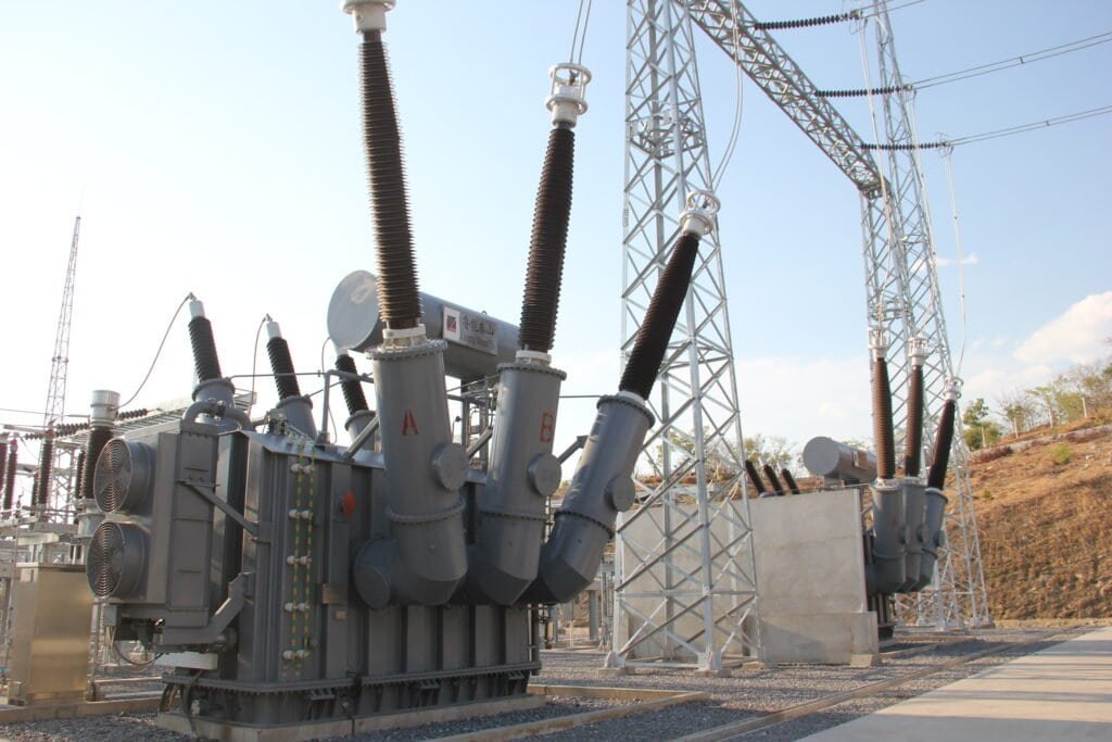
Energy losses are an unavoidable part of power transformer operation, but excessive losses can significantly reduce efficiency and increase operating costs. When a transformer operates continuously under load, even relatively small inefficiencies can accumulate into substantial energy waste and heat generation over its service life. If losses are not properly controlled, they can also increase temperature rise, accelerate insulation aging, and reduce the transformer's overall reliability. Understanding how different types of losses affect transformer performance is therefore essential when specifying and purchasing power transformers.
Energy losses affect power transformer performance by reducing efficiency, increasing heat generation, raising operating costs, and potentially accelerating insulation aging. The two primary categories are no-load losses, mainly core losses that occur whenever the transformer is energized, and load losses, mainly winding losses that increase with load current. Selecting low-loss core materials, appropriately sized conductors, effective cooling systems, and high-efficiency transformer designs can significantly reduce these losses and improve lifecycle performance.
Energy efficiency should therefore be evaluated over the transformer's entire operating life rather than by purchase price alone. A transformer with a higher initial cost may provide greater long-term value if its reduced losses generate substantial energy savings throughout decades of operation.
How Do Energy Losses Affect the Performance of Power Transformers?
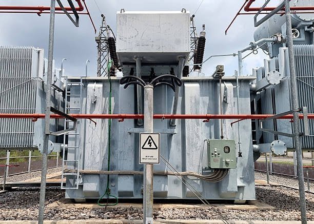
Energy losses are an unavoidable part of transformer operation, but their magnitude has a direct effect on efficiency, temperature rise, operating cost, insulation life, and long-term reliability. A transformer with excessive losses may still deliver its rated voltage and capacity during commissioning, yet continuously waste energy and operate hotter than necessary throughout its service life. Power-transformer energy losses are mainly divided into no-load losses and load losses: no-load losses occur primarily in the magnetic core whenever the transformer is energized, while load losses increase with winding current and conductor resistance. Reducing both losses improves transformer efficiency, lowers heat generation, reduces operating costs, and can extend insulation life. For buyers, guaranteed no-load loss, load loss, efficiency at realistic loading, and total lifecycle energy cost should therefore be evaluated together rather than judging a transformer only by its purchase price.
Transformer energy losses occur only when the transformer is heavily loaded.False
Core-related no-load losses occur whenever the transformer is energized, even when little or no useful load is connected, while load-related losses increase as current flows through the windings.
What Are the Main Types of Transformer Energy Losses?
Transformer losses are generally divided into two major categories: no-load losses and load losses.
No-load losses are primarily associated with the magnetic core. They exist whenever the transformer is energized because the alternating magnetic flux continuously changes within the core.
Load losses are primarily associated with current flowing through the windings and other structural components. They increase as transformer loading increases.
A simplified view is:
| Loss Category | Main Source | Dependence on Load | Main Performance Effect |
|---|---|---|---|
| No-load loss | Core magnetization | Relatively independent of load | Continuous energy consumption |
| Load loss | Winding resistance and stray effects | Strongly increases with current | Heating and reduced efficiency |
| Dielectric loss | Insulation system | Depends on design and voltage | Additional heat and aging |
| Auxiliary loss | Fans, pumps, controls | Depends on cooling system | Reduced net efficiency |
For most practical procurement decisions, core loss and load loss are the two most important guaranteed loss values.
Why Do No-Load Losses Matter?
No-load loss is sometimes underestimated because it does not change significantly with the transformer's load.
However, a transformer can remain energized for thousands of hours each year.
If a transformer has a 4 kW no-load loss and remains energized continuously:
4 kW × 8,760 hours/year = 35,040 kWh/year
Over a 20-year operating period, ignoring changes in operating conditions, that becomes approximately:
700,800 kWh
of energy consumption associated with no-load loss alone.
This explains why core-loss performance matters even for transformers that operate at relatively low average loading.
No-load losses are particularly important for:
- Distribution transformers
- Transformers that remain energized continuously
- Standby transformers
- Renewable-energy installations with long energized periods
- Industrial facilities with variable demand
- Systems with significant off-peak operation
What Causes Core Loss?
Core loss primarily consists of hysteresis loss and eddy-current loss.
Hysteresis loss results from repeated magnetization and demagnetization of the magnetic core material.
Eddy-current loss results from circulating currents induced within conductive core material by the alternating magnetic field.
Core design therefore has a major influence on transformer efficiency.
Important factors include:
- Electrical-steel grade
- Grain orientation
- Lamination thickness
- Magnetic flux density
- Joint design
- Core assembly quality
- Manufacturing stress
High-quality grain-oriented electrical steel and carefully controlled core construction can significantly reduce no-load losses.
Why Does Load Loss Increase With Current?
The most familiar component of load loss is winding resistance.
When current flows through a conductor, electrical energy is dissipated as heat.
The relationship can be simplified as:
[P_{\text{loss}}=I^2R]
This is important because the loss increases with the square of current.
For example, if current doubles while resistance remains constant, resistive loss theoretically increases by a factor of four.
This makes load management particularly important.
A transformer operating near full load can therefore produce substantially more heat and energy loss than the same transformer operating at half load.
How Do Energy Losses Affect Transformer Efficiency?
Transformer efficiency is commonly expressed as useful output power divided by input power.
In practical terms:
Higher losses → higher input power required → lower efficiency
A transformer with 1,000 kW of useful output and 10 kW of total losses requires approximately 1,010 kW of input power under those conditions.
Its efficiency is approximately:
1,000 / 1,010 ≈ 99.01%
Although a 0.99% loss may appear small, the absolute energy cost can become significant when the transformer operates continuously for decades.
How Do Losses Affect Transformer Temperature?
Almost all electrical losses ultimately become heat.
This heat must be removed through the transformer's cooling system.
For an oil-filled transformer, heat is transferred through the insulating liquid and cooling surfaces. For a dry-type transformer, heat is transferred primarily through air.
If losses increase without a corresponding increase in heat-removal capability, winding and core temperatures rise.
Higher temperature can accelerate insulation aging.
This creates an important chain:
Higher losses → more heat → higher operating temperature → faster insulation aging → potentially shorter service life
Therefore, minimizing losses is not only an energy-efficiency objective. It is also a reliability objective.
How Does Loading Influence Total Losses?
The relationship between load and losses is not linear.
No-load loss remains relatively stable as loading changes, while load loss increases approximately with the square of load current.
A simplified conceptual model is:
[P_{\text{total}} \approx P0 + P{\text{load}}]
and load loss can be approximated as proportional to the square of the load fraction.
| Transformer Loading | Approximate Relative Load Loss* |
|---|---|
| 25% | 6.25% |
| 50% | 25% |
| 75% | 56.25% |
| 100% | 100% |
| 125% | 156.25% |
*Illustrative relationship assuming resistive loss proportional to current squared; actual transformer losses include additional components and operating conditions.
This is why the most efficient operating point depends on the relationship between fixed core losses and variable load losses.
What Is the Difference Between High No-Load and High Load Loss?
The distinction matters when selecting transformers for different duty cycles.
A transformer with very low no-load loss may be advantageous when it remains energized continuously at low or moderate loading.
A transformer with very low load loss may provide greater benefits when it operates at high loading for substantial periods.
For procurement, buyers should therefore provide the expected load profile rather than asking for the lowest possible loss in only one category.
How Do Losses Affect Electricity Costs?
Energy losses create an operating expense for the owner.
A useful simplified calculation is:
Annual loss energy = transformer loss × operating hours
For variable loading, the calculation should use the actual load profile rather than a single nameplate value.
For example, assume a transformer has:
- 5 kW no-load loss
- 20 kW load loss at rated load
- 8,760 energized hours per year
If it operated continuously at full load, the theoretical annual loss energy would be approximately:
(5 + 20) × 8,760 = 219,000 kWh/year
At an illustrative electricity cost of $0.10/kWh, this would represent approximately:
$21,900 per year
Actual costs depend on the tariff, loading profile, power factor, operating hours, and other system conditions.
This demonstrates why a slightly higher initial transformer price can sometimes be justified by significantly lower guaranteed losses.
How Should Buyers Compare Purchase Price With Losses?
Transformer procurement should consider total cost of ownership, not just the initial quotation.
A basic comparison can include:
Purchase price + installation cost + present value of energy losses + maintenance cost + expected replacement cost
For long-life equipment, energy losses can become a major component of lifecycle cost.
Consider two hypothetical transformers:
| Parameter | Transformer A | Transformer B |
|---|---|---|
| Purchase price | $100,000 | $110,000 |
| No-load loss | 6 kW | 4 kW |
| Rated load loss | 24 kW | 18 kW |
| Expected operating life | 25 years | 25 years |
| Initial cost | Lower | Higher |
| Loss performance | Higher | Lower |
Transformer B costs more initially, but the additional investment may be recovered through reduced electricity consumption if the loading profile and energy tariff justify it.
The correct decision requires an actual lifecycle calculation.
How Do Core Materials Affect Energy Losses?
Core material is particularly important for no-load performance.
Traditional transformer cores commonly use grain-oriented electrical steel. Improvements in steel grade, lamination thickness, magnetic properties, and processing can reduce core losses.
Amorphous metal is another technology that can provide very low no-load losses in suitable applications.
However, core material should not be evaluated independently.
Manufacturing quality also matters.
Poor cutting, excessive mechanical stress, damaged insulation between laminations, or poor joint construction can compromise the theoretical performance of high-grade core material.
Therefore:
Material quality + core design + manufacturing quality = actual core-loss performance
How Do Winding Designs Affect Load Loss?
Winding resistance depends on conductor material, conductor cross-sectional area, winding geometry, conductor length, and operating temperature.
Copper and aluminum are common conductor materials.
The winding design must balance:
- Current density
- Thermal performance
- Mechanical strength
- Short-circuit withstand
- Space utilization
- Manufacturing cost
Reducing conductor resistance can lower load losses, but simply increasing conductor size is not always the best solution because transformer dimensions, weight, material cost, and mechanical design also change.
Do Dry-Type Transformers Have Different Loss Considerations?
Yes, but the fundamental loss mechanisms remain similar.
Dry-type transformers still have:
- Core losses
- Winding losses
- Stray losses
- Dielectric losses
- Auxiliary losses where fans are installed
Their cooling method changes the thermal-management requirements.
Because dry-type transformers rely on air, excessive losses can be particularly important in enclosed rooms. The heat generated by the transformer must be removed through ventilation.
A low-loss dry-type transformer can therefore offer both:
Lower electricity consumption + lower heat generation
This can be valuable in buildings and industrial electrical rooms.
How Do Losses Affect Transformer Capacity?
Losses also influence how much useful power a transformer can deliver within its thermal limits.
A transformer with excessive losses generates additional heat, leaving less thermal margin for useful load.
This is why transformer capacity should not be considered independently from loss performance and cooling.
Two transformers with the same MVA rating may have different:
- No-load losses
- Load losses
- Temperature rise
- Cooling requirements
- Efficiency
- Operating costs
The nameplate rating alone does not tell the complete performance story.
What Role Does Power Factor Play?
Transformer current depends on apparent power rather than simply useful real power.
For a given real power demand, a lower power factor requires higher current.
Higher current increases winding-related losses.
Therefore, poor power factor can indirectly increase transformer losses and heating.
Industrial facilities with large motors and inductive loads should evaluate:
- Power factor
- Reactive power
- Peak current
- Compensation equipment
- Harmonic distortion
Improving power factor can reduce current and consequently reduce some current-dependent losses.
How Do Losses Influence Reliability?
Energy efficiency and reliability are closely connected.
Excessive losses cause heat. Heat accelerates insulation aging and can increase the probability of thermal deterioration.
Other consequences may include:
- Higher winding temperature
- Reduced overload margin
- Increased cooling requirements
- Faster insulation aging
- Greater maintenance requirements
- Higher operating costs
Therefore, low-loss transformer design should be viewed as part of a broader reliability strategy.
How Can Buyers Evaluate Transformer Losses?
Buyers should request guaranteed values rather than relying on generic efficiency claims.
Important procurement information includes:
- No-load loss
- Load loss
- Total loss at specified loading
- Guaranteed efficiency
- Temperature rise
- Test conditions
- Applicable tolerance
- Factory test reports
The comparison must use the same reference conditions.
For example, comparing one supplier's load loss at one temperature with another supplier's value at a different reference temperature can produce misleading conclusions.
What Should Be Included in the Technical Specification?
A good transformer specification should define:
- Rated capacity
- Primary and secondary voltage
- Frequency
- Connection group
- Impedance
- No-load loss guarantee
- Load loss guarantee
- Temperature-rise limit
- Cooling method
- Ambient conditions
- Harmonic requirements
- Short-circuit withstand
- Noise requirements
- Applicable standards
- Factory testing
- Acceptance criteria
Loss guarantees should be clearly stated in the purchase contract.
What Are the Main Types of Energy Losses in Power Transformers?

Power transformers are designed to transfer electrical energy efficiently from one voltage level to another, but no transformer can operate without some energy loss. Understanding where these losses occur is important because they directly influence transformer efficiency, temperature rise, operating cost, cooling requirements, and insulation life. For buyers and engineers, the key is not simply to ask for the “lowest transformer loss,” but to understand which loss mechanisms dominate under the actual operating conditions. The main energy losses in power transformers are core loss (no-load loss), winding or copper loss (load loss), stray load loss, dielectric loss, and auxiliary losses from cooling and monitoring equipment. Core loss exists whenever the transformer is energized, while current-dependent losses increase with loading.
Power transformer losses are caused only by resistance in the copper windings.False
Winding resistance causes an important portion of load loss, but transformers also experience core hysteresis and eddy-current losses, stray load losses, dielectric losses, and auxiliary losses depending on the design.
What Are the Main Transformer Loss Categories?
The losses can first be divided into losses that exist independently of load and losses that increase with current.
| Loss Type | Main Cause | Load Dependence | Typical Importance |
|---|---|---|---|
| Core loss | Hysteresis and eddy currents in the core | Mainly independent of load | High |
| Winding loss | Conductor resistance | Approximately proportional to current² | High |
| Stray load loss | Leakage flux inducing currents in conductors and structural parts | Increases with load | Moderate to high |
| Dielectric loss | Losses in insulation under electric field | Voltage and insulation dependent | Usually smaller |
| Auxiliary loss | Fans, pumps, controls, monitoring | Depends on cooling and accessories | Application-dependent |
For most power-transformer purchasing decisions, core loss and load loss are the principal guaranteed loss values. The other categories become increasingly relevant when analyzing high-voltage, high-capacity, heavily loaded, or specialized transformers.
What Is Core Loss or No-Load Loss?
Core loss is the energy consumed by the transformer magnetic circuit when the transformer is energized, even if there is little or no external load.
It mainly consists of two mechanisms:
- Hysteresis loss
- Eddy-current loss
Because the magnetic flux alternates continuously at the operating frequency, the core experiences these losses throughout normal energized operation.
This is why core loss is also commonly called no-load loss.
A transformer with a 3 kW no-load loss that remains energized continuously consumes approximately:
3 kW × 8,760 hours = 26,280 kWh/year
The actual cost depends on the electricity tariff, operating schedule, and system conditions, but this illustrates why low core loss is particularly valuable for transformers that remain energized around the clock.
How Does Hysteresis Loss Occur?
Hysteresis loss is associated with the repeated magnetization and demagnetization of the magnetic core.
When alternating voltage is applied to a transformer winding, it creates alternating magnetic flux in the core. The magnetic domains within the core material repeatedly change orientation.
Because the magnetic material does not respond without energy expenditure, some electrical energy is converted into heat during each cycle.
Hysteresis loss is influenced by:
- Core material
- Magnetic properties
- Frequency
- Maximum flux density
- Core construction
- Manufacturing stress
High-quality electrical steel is therefore important for transformer efficiency.
What Is Eddy-Current Loss in the Core?
Eddy-current loss occurs because the alternating magnetic flux induces circulating electrical currents within the conductive core material.
These currents generate heat and consume energy.
Transformer cores are therefore constructed from thin electrically insulated laminations rather than a single solid block of steel.
Thinner laminations increase electrical resistance to circulating currents and reduce eddy-current loss.
Important design factors include:
- Lamination thickness
- Electrical resistivity
- Insulation between laminations
- Magnetic flux density
- Core manufacturing quality
This is one reason that core material selection and manufacturing quality can have a direct effect on transformer no-load performance.
What Is Winding or Copper Loss?
Winding loss is the electrical energy dissipated by current flowing through the transformer conductors.
The basic relationship is:
[P_{\text{winding}}=I^2R]
This explains an important feature of transformer operation: winding loss increases rapidly as load current increases.
If current doubles, the basic resistive component of loss increases approximately four times, assuming resistance remains constant.
| Load Current | Relative Current | Relative I²R Loss |
|---|---|---|
| 25% | 0.25 | 6.25% |
| 50% | 0.50 | 25% |
| 75% | 0.75 | 56.25% |
| 100% | 1.00 | 100% |
| 125% | 1.25 | 156.25% |
These are illustrative relative values, not complete transformer test results.
Winding loss is affected by:
- Conductor material
- Conductor cross-section
- Winding length
- Current density
- Operating temperature
- Winding geometry
- Connection resistance
Copper and aluminum are both commonly used as transformer winding materials.
What Is Stray Load Loss?
Not all load-related losses occur directly through winding DC resistance.
Transformer leakage flux can interact with conductive components and create additional circulating currents. These produce what are commonly referred to as stray load losses.
They can occur in:
- Transformer tanks
- Clamping structures
- Structural steel
- Winding conductors
- Other metallic components exposed to leakage flux
Stray losses generally increase as transformer loading increases because leakage flux and current-related magnetic effects become stronger.
For large power transformers, careful electromagnetic and structural design is important to control these losses.
What Is Dielectric Loss?
Dielectric loss occurs in the transformer's insulation system when it is subjected to an alternating electric field.
It is associated with the imperfect insulating behavior of dielectric materials.
Compared with core and winding losses, dielectric losses are often smaller in ordinary transformer operation, but they become important in high-voltage applications and when evaluating insulation condition.
Factors influencing dielectric loss include:
- Insulation material
- Moisture
- Temperature
- Electric-field stress
- Aging
- Contamination
- Insulation geometry
For high-voltage power transformers, dielectric performance should therefore be considered together with insulation design and partial-discharge performance.
What Are Auxiliary Losses?
Some transformers require equipment that consumes additional electrical energy during operation.
Examples include:
- Cooling fans
- Oil pumps
- Control systems
- Monitoring equipment
- Heating systems
- On-load tap-changer equipment
For a naturally cooled transformer, auxiliary consumption may be relatively small.
For a large forced-cooled transformer, fans and pumps can consume additional power.
This is why buyers evaluating overall system efficiency should consider auxiliary power consumption, especially for large installations.
Which Losses Are Constant and Which Vary With Load?
This distinction is particularly useful when selecting transformer capacity.
Core loss is broadly treated as a fixed loss at a given voltage and frequency.
Winding and other load-related losses increase with transformer current.
A simplified total-loss relationship can therefore be expressed as:
[P{\text{total}} \approx P{\text{core}}+P_{\text{load}}]
This means that a transformer operating at low load still consumes energy because its core remains magnetized.
At high loading, current-dependent losses become increasingly dominant.
Why Does Transformer Loss Matter to Buyers?
Losses affect more than efficiency.
They influence:
- Annual electricity consumption
- Transformer temperature
- Cooling-system requirements
- Insulation aging
- Available overload margin
- Lifecycle cost
- Carbon emissions associated with electricity consumption
For a transformer expected to operate for 20–30 years, even a modest difference in guaranteed losses can have a significant economic effect.
This is particularly important for:
- Utility transformers
- Distribution transformers
- Industrial transformers
- Data-center transformers
- Renewable-energy transformers
- Continuously energized transformers
How Do Transformer Losses Become Heat?
Almost all electrical losses eventually become thermal energy.
The basic chain is:
Electrical input → useful electrical output + losses → heat
That heat must then be transferred away through the cooling system.
If losses increase, the cooling system must remove more heat to maintain the required temperature rise.
This creates an important connection between efficiency and reliability.
A low-loss transformer generally has less heat to dissipate, which can improve thermal margin when other design conditions are equal.
How Do Energy Losses Affect Transformer Efficiency?
Transformer efficiency is the ratio between useful output power and total input power.
For example, if a transformer supplies 1,000 kW of useful output and experiences 10 kW of total loss, its input requirement is approximately 1,010 kW.
The efficiency is approximately:
1,000 ÷ 1,010 = 99.01%
The percentage looks small, but the absolute energy consumption can become substantial when the transformer operates continuously.
This is why buyers should evaluate losses in terms of annual kWh and lifecycle cost, rather than focusing exclusively on efficiency percentages.
How Do Core and Winding Losses Differ in Procurement?
The difference is important because each loss is controlled by different design choices.
Core loss is strongly influenced by:
- Electrical-steel grade
- Lamination thickness
- Flux density
- Core-joint construction
- Core assembly quality
Load loss is strongly influenced by:
- Conductor material
- Conductor size
- Current density
- Winding geometry
- Stray-flux control
- Operating temperature
Therefore, reducing one loss category does not automatically minimize the other.
What Should Buyers Ask Transformer Suppliers?
A professional transformer specification should request clear guaranteed loss values.
Buyers should ask suppliers for:
- Guaranteed no-load loss
- Guaranteed load loss
- Total loss at specified loading
- Reference temperature for load-loss values
- Applicable measurement tolerance
- Routine test results
- Type-test information where applicable
- Efficiency under specified operating conditions
- Auxiliary power consumption where relevant
- Temperature-rise guarantees
The loss values should be compared under equivalent test conditions.
How Should Buyers Evaluate Losses for Different Applications?
The best loss profile depends on the expected load-duration curve.
| Application | Important Loss Consideration |
|---|---|
| Continuously energized transformer | Low no-load loss |
| High-utilization industrial transformer | Low load loss |
| Variable-load commercial transformer | Balance between both |
| Standby transformer | Low no-load loss can be valuable |
| Data center | Both losses and thermal performance |
| Renewable-energy transformer | Losses under converter loading |
| Large utility transformer | Lifecycle loss cost and reliability |
A transformer should therefore be optimized for its actual operating pattern, not simply its maximum rating.
How Do Core and Winding Losses Affect Power Transformer Efficiency?

Core and winding losses are the two most important loss categories that engineers consider when evaluating power-transformer efficiency. Although both ultimately appear as heat, they behave very differently during operation. Core loss is primarily associated with the magnetic core and occurs whenever the transformer is energized, while winding loss is mainly caused by conductor resistance and increases strongly with load current. Core loss establishes a relatively continuous energy penalty, whereas winding loss becomes increasingly important as transformer loading rises. The combined effect determines transformer efficiency, temperature rise, cooling requirements, operating cost, and part of the transformer's long-term reliability.
Core loss and winding loss affect transformer efficiency in exactly the same way because both increase proportionally with transformer load.False
Core loss is primarily related to applied voltage, frequency, and core magnetic conditions and remains present when the transformer is energized, whereas winding loss is strongly dependent on load current and approximately follows an I²R relationship.
What Is the Difference Between Core Loss and Winding Loss?
The simplest distinction is their relationship with transformer loading.
Core loss is predominantly a fixed loss. Winding loss is predominantly a variable loss.
When a transformer is connected to the power system, alternating voltage establishes magnetic flux in the core. The core continuously experiences magnetic reversal, producing hysteresis and eddy-current losses. This happens whether the transformer is carrying 10% load or 100% load.
Winding loss behaves differently. When current flows through the primary and secondary conductors, their electrical resistance causes power dissipation. As current increases, this loss increases approximately with the square of current.
| Characteristic | Core Loss | Winding Loss |
|---|---|---|
| Main location | Magnetic core | Primary and secondary windings |
| Common name | No-load loss | Load loss |
| Exists when energized without external load? | Yes | Very small compared with loaded condition |
| Main dependence | Voltage, frequency, flux density, core material | Current, resistance, temperature |
| Approximate load relationship | Relatively constant | Approximately proportional to I² |
| Main heat location | Core | Windings and nearby structures |
| Main design factors | Electrical steel, laminations, flux density, joints | Conductor size, material, geometry, current density |
| Procurement importance | High | High |
This difference is fundamental to transformer efficiency analysis.
How Does Core Loss Reduce Efficiency?
Core loss consumes energy continuously.
Suppose a transformer has a guaranteed no-load loss of 4 kW. If it remains energized for a full year:
4 kW × 8,760 hours = 35,040 kWh/year
That energy does not depend on whether the transformer is delivering its full rated capacity at every moment.
This makes core loss especially important for transformers that:
- Remain energized continuously
- Operate at low average load
- Serve variable commercial loads
- Remain energized during off-peak periods
- Operate as standby equipment
- Are installed in renewable-energy or industrial systems with long energized periods
A transformer with low no-load loss can therefore provide an economic advantage even when its average load is relatively low.
Why Does the Core Consume Energy When There Is No Load?
“No load” does not mean “no magnetic activity.”
The transformer primary remains connected to the AC supply. The applied voltage establishes alternating magnetic flux in the core.
The magnetic material experiences repeated magnetization and demagnetization. This produces hysteresis loss.
At the same time, alternating magnetic flux induces circulating currents within the electrically conductive core material. These are eddy-current losses.
Consequently, the transformer consumes energy even though very little useful power is being delivered to an external load.
This is why the term no-load loss should not be interpreted as “zero-load operation with zero energy consumption.”
How Does Core Material Influence Efficiency?
Core material is one of the most important factors controlling no-load performance.
Modern power transformers commonly use grain-oriented electrical steel. Its magnetic properties are optimized for transformer applications.
Core-loss performance depends on factors such as:
- Steel grade
- Magnetic permeability
- Electrical resistivity
- Lamination thickness
- Flux density
- Grain orientation
- Core-joint design
- Manufacturing stress
Reducing core loss requires more than selecting a high-grade material. Manufacturing quality is equally important.
Improper cutting, excessive mechanical stress, poor joints, or damaged lamination insulation can increase actual core losses.
Therefore:
Core material quality + core geometry + manufacturing quality = actual no-load performance
How Does Winding Loss Reduce Efficiency?
Winding loss is primarily associated with electrical resistance in the transformer conductors.
The fundamental relationship is commonly represented by the I²R principle. As current increases, resistive heating rises rapidly.
For example, if current increases from 50% to 100% of rated current, the basic resistive component of winding loss increases by approximately:
(1.0 / 0.5)² = 4
Therefore, doubling current can approximately quadruple the resistive winding loss.
This is why a transformer can have excellent efficiency at moderate loading but experience significantly greater losses near full load.
What Determines Winding Loss?
Winding loss depends on several design and operating parameters.
Important factors include:
- Conductor material
- Conductor cross-sectional area
- Winding length
- Current density
- Winding configuration
- Operating temperature
- Connection resistance
- Stray magnetic effects
Copper and aluminum are both widely used for transformer windings.
A designer must balance conductor resistance against:
- Material cost
- Transformer dimensions
- Weight
- Thermal performance
- Mechanical strength
- Short-circuit withstand
Simply increasing conductor size may reduce resistance, but it can also increase transformer cost and physical dimensions.
Why Does Winding Temperature Matter?
Winding resistance changes with temperature.
As conductor temperature rises, electrical resistance generally increases. Higher resistance then causes greater resistive losses for the same current.
This creates a feedback relationship:
Higher loss → higher temperature → higher resistance → additional winding loss
Transformer cooling therefore plays an important role in maintaining efficient operation.
For this reason, a transformer specification should consider not only rated load loss but also the reference temperature at which the load-loss value is guaranteed.
How Do Core and Winding Losses Combine?
A simplified transformer-loss model is:
[P{\text{total}} \approx P{\text{core}} + P_{\text{winding}}]
Actual transformer loss calculations may also include stray load loss, dielectric loss, and auxiliary power consumption.
Transformer efficiency can then be understood conceptually as:
[\eta = \frac{P{\text{out}}}{P{\text{out}}+P_{\text{loss}}}]
The lower the total loss for a given useful output, the higher the efficiency.
Why Does the Optimal Efficiency Point Occur at a Particular Load?
Because core and winding losses behave differently.
Core loss remains relatively constant, while winding loss increases approximately with the square of current.
At very low load, core loss represents a relatively large proportion of the transformer's total input power.
As loading increases, useful output power increases faster than the fixed core loss, so efficiency improves.
Eventually, winding loss becomes increasingly significant. Beyond a certain operating point, the increasing load loss causes efficiency to stop improving and eventually decline.
For a simplified transformer model, maximum efficiency occurs when the variable load loss is approximately equal to the fixed core loss.
This principle is useful for understanding why transformer sizing and operating profile are closely connected to efficiency.
How Does Transformer Loading Change the Loss Balance?
Consider a simplified transformer with:
- Core loss = 5 kW
- Full-load winding loss = 20 kW
The approximate winding-loss relationship can be illustrated as follows:
| Loading | Core Loss | Approx. Winding Loss | Approx. Total of These Two Losses |
|---|---|---|---|
| 25% | 5 kW | 1.25 kW | 6.25 kW |
| 50% | 5 kW | 5 kW | 10 kW |
| 75% | 5 kW | 11.25 kW | 16.25 kW |
| 100% | 5 kW | 20 kW | 25 kW |
These values are illustrative, assuming winding loss follows the idealized square-current relationship.
The table demonstrates the key point: at low loading, core loss dominates; at high loading, winding loss becomes increasingly important.
How Do Losses Affect Temperature Rise?
Both core and winding losses become heat.
However, winding losses are especially important because significant heat is generated directly inside the windings.
Higher total losses require more effective heat removal.
If a transformer generates excessive heat, the resulting temperature rise can:
- Reduce thermal margin
- Increase insulation stress
- Accelerate aging
- Reduce overload capability
- Increase cooling-system requirements
For dry-type transformers, this makes room ventilation particularly important.
For oil-filled transformers, it affects fluid circulation and radiator or cooler requirements.
Can Lower Losses Improve Transformer Reliability?
Yes, although the relationship should be understood correctly.
Lower losses mean less heat generation under equivalent operating conditions. Lower heat generation can reduce operating temperature and increase thermal margin.
This can support longer insulation life and more stable operation.
The relationship can be summarized as:
Lower losses → lower heat generation → lower temperature rise → greater insulation-life margin
However, transformer reliability also depends on:
- Insulation quality
- Mechanical strength
- Short-circuit withstand
- Moisture control
- Cooling
- Protection
- Installation quality
- Maintenance
- Operating conditions
Low loss alone cannot guarantee reliability.
How Do Core and Winding Losses Affect Lifecycle Cost?
The initial transformer price is only one component of the total cost.
A simplified lifecycle evaluation can consider:
Purchase cost + installation cost + energy-loss cost + maintenance cost + eventual replacement cost
For example, suppose two transformers have the same rated capacity but different guaranteed losses.
| Parameter | Transformer A | Transformer B |
|---|---|---|
| Purchase price | $100,000 | $108,000 |
| No-load loss | 5 kW | 3.5 kW |
| Full-load loss | 22 kW | 17 kW |
| Initial cost | Lower | Higher |
| Loss performance | Higher | Lower |
Transformer B costs more initially but may save significantly more energy during its operating life.
Whether the additional $8,000 is justified depends on:
- Annual operating hours
- Average load
- Peak load
- Electricity tariff
- Expected service life
- Discount rate
- Energy-price assumptions
This is why buyers should perform a lifecycle-cost analysis rather than selecting the lowest initial quotation.
How Should Buyers Evaluate Core Loss?
For procurement, buyers should request a guaranteed no-load loss in kW.
The specification should identify:
- Rated voltage
- Rated frequency
- No-load loss
- Measurement method
- Applicable tolerance
- Factory test requirements
Buyers should compare all suppliers under equivalent test conditions.
A lower number is generally desirable, but it should be evaluated together with the transformer price and expected energized hours.
How Should Buyers Evaluate Winding Loss?
Load loss should be evaluated at a clearly defined reference condition.
Important information includes:
- Rated current
- Load loss at rated load
- Reference winding temperature
- Measurement method
- Applicable tolerances
- Stray-loss treatment
- Factory acceptance criteria
This is especially important because winding resistance changes with temperature.
Comparing two load-loss values without considering their reference conditions can produce a misleading result.
How Do Harmonics Affect Winding-Related Losses?
Modern industrial and commercial systems increasingly contain nonlinear loads.
Examples include:
- Variable-frequency drives
- Solar inverters
- Battery energy-storage converters
- UPS systems
- Rectifiers
- Data-center equipment
Harmonic currents can increase additional conductor and stray losses.
Therefore, a transformer designed for a conventional sinusoidal load may not have the same thermal performance when subjected to significant harmonic currents.
Buyers should provide the transformer supplier with harmonic information when relevant.
Does Oversizing Reduce Transformer Losses?
Oversizing can reduce current-dependent winding losses at a given real-power load because the transformer operates at a lower percentage of its rated capacity.
However, oversizing does not eliminate core loss.
In fact, a larger transformer may have a different no-load loss and may cost more.
Therefore, simply choosing a much larger transformer is not automatically the best efficiency strategy.
The goal should be to select a capacity that appropriately matches:
Current demand + expected growth + operating profile + thermal margin
What Should Buyers Include in Transformer Specifications?
A technically complete transformer specification should clearly define:
- Rated capacity
- Primary and secondary voltage
- Frequency
- Connection group
- Impedance
- Guaranteed no-load loss
- Guaranteed load loss
- Reference temperature
- Temperature rise
- Cooling method
- Harmonic requirements
- Short-circuit withstand
- Applicable standards
- Factory routine tests
- Acceptance criteria
For large or critical transformers, buyers should also consider witnessed factory testing and contractual remedies for loss-performance deviations.
How Does Heat Generated by Energy Losses Affect Power Transformer Performance and Lifespan?
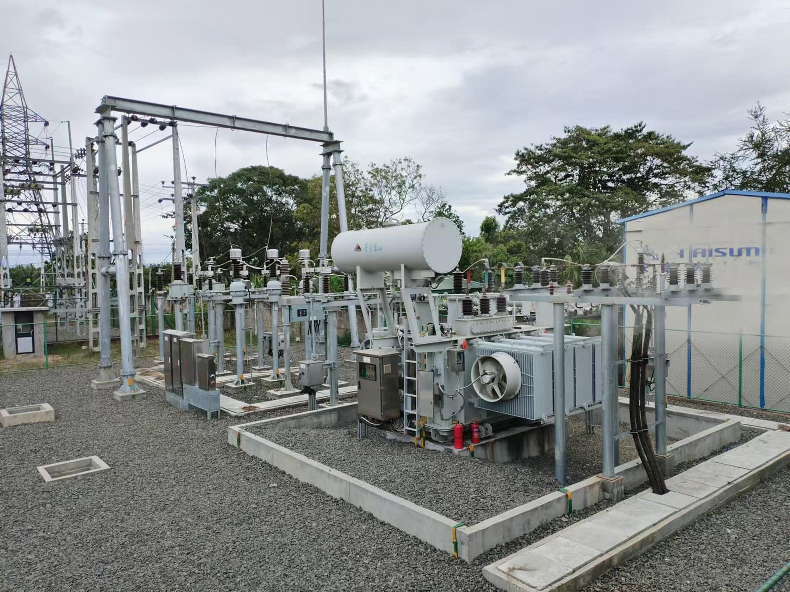
Every power transformer converts some electrical energy into heat through core loss, winding loss, stray loss, and other internal losses. If that heat is not removed effectively, transformer temperature rises, electrical resistance increases, insulation ages faster, and the available thermal margin decreases. Over time, excessive temperature can turn a manageable efficiency problem into a reliability problem, increasing the risk of insulation deterioration, winding damage, and premature transformer failure. Heat generated by transformer energy losses directly affects performance because higher internal temperature increases thermal stress, can increase winding resistance and load losses, reduces overload capability, and accelerates insulation aging. Effective core and winding design, appropriate cooling, accurate temperature monitoring, and operation within the specified thermal limits are therefore essential for achieving the expected transformer lifespan.
Transformer heat generated by energy losses mainly affects efficiency and has little effect on transformer lifespan.False
Excessive temperature is a major factor in insulation aging. Higher operating temperatures can accelerate insulation deterioration and reduce the transformer's available service-life margin.
Why Do Transformer Energy Losses Become Heat?
The basic energy balance of a transformer is straightforward:
Electrical input = useful electrical output + internal losses
The energy represented by the internal losses is ultimately converted primarily into heat.
The major contributors include:
| Heat Source | Main Mechanism | Thermal Significance |
|---|---|---|
| Core loss | Hysteresis and eddy currents | Relatively continuous |
| Winding loss | Conductor resistance, approximately I²R | Strongly increases with load |
| Stray load loss | Leakage flux inducing currents in conductive parts | Increases with loading |
| Dielectric loss | Energy dissipation in insulation | Usually smaller but important at high voltage |
| Auxiliary loss | Fans, pumps, controls | Depends on cooling configuration |
This means that transformer thermal performance cannot be separated from transformer efficiency.
A lower-loss transformer generally has less heat to remove under comparable operating conditions.
How Does Temperature Affect Transformer Efficiency?
Temperature has an especially important relationship with winding resistance.
As conductor temperature increases, conductor resistance generally increases. Because winding loss is related to current and resistance, higher temperature can increase the resistive component of loss for a given current.
This creates a practical feedback relationship:
Energy loss → heat → higher conductor temperature → higher resistance → additional loss
The effect is not normally an uncontrolled runaway process in a properly designed transformer, because the cooling system establishes a thermal equilibrium. However, inadequate cooling, excessive loading, blocked ventilation, high ambient temperature, or abnormal operating conditions can push the transformer beyond its intended thermal range.
How Does Heat Affect Transformer Insulation?
For many power transformers, insulation aging is one of the most important consequences of excessive heat.
Transformer insulation is exposed to electrical, thermal, mechanical, and environmental stresses throughout its service life. Temperature accelerates many of the chemical processes responsible for insulation deterioration.
As insulation ages, its mechanical and dielectric properties can deteriorate.
Potential consequences include:
- Reduced dielectric strength
- Loss of mechanical integrity
- Increased brittleness
- Greater vulnerability to electrical faults
- Reduced ability to withstand short-circuit forces
- Shorter expected service life
For this reason, controlling temperature is fundamentally a lifespan-management strategy, not merely a cooling issue.
What Happens When a Transformer Operates Too Hot?
A transformer operating above its specified thermal limits may experience several problems simultaneously.
First, winding resistance increases.
Second, losses increase.
Third, more heat is generated.
Fourth, insulation experiences greater thermal stress.
Fifth, the remaining thermal margin decreases.
This can reduce the transformer's ability to withstand temporary overloads or abnormal conditions.
| Thermal Condition | Likely Effect |
|---|---|
| Normal temperature | Expected efficiency and insulation aging |
| Elevated temperature | Increased losses and accelerated aging |
| Repeated overheating | Greater insulation deterioration |
| Sustained excessive temperature | Significant reduction in service-life margin |
| Severe thermal abnormality | Potential winding or insulation damage |
The actual severity depends on transformer design, insulation system, duration, ambient conditions, and the magnitude of the temperature excursion.
Why Is Winding Temperature Particularly Important?
The winding is one of the most important locations for transformer thermal analysis because electrical current directly generates heat within the conductors.
The simplified relationship is:
[P_{\text{winding}}=I^2R]
As current rises, winding heat generation increases rapidly.
This is why a transformer operating at high load needs an effective cooling path from the winding to the surrounding cooling medium.
For liquid-filled transformers, heat moves through the insulating liquid and cooling system.
For dry-type transformers, heat must be transferred to surrounding air.
In either case, poor heat transfer can cause the winding temperature to rise even when the transformer's electrical loading appears acceptable.
How Does Ambient Temperature Affect Transformer Lifespan?
The transformer does not operate in isolation from its surroundings.
If the ambient temperature increases, the transformer has less temperature difference available for dissipating its internally generated heat.
For example, a transformer operating in a cool electrical room has a very different thermal environment from the same transformer installed in a hot industrial facility.
Buyers should therefore provide manufacturers with:
- Maximum ambient temperature
- Average ambient temperature
- Installation altitude
- Indoor or outdoor conditions
- Ventilation information
- Solar exposure where relevant
- Cooling configuration
A transformer designed for standard conditions should not automatically be assumed suitable for extreme environmental conditions.
How Does Cooling Protect Transformer Lifespan?
The purpose of a transformer cooling system is to maintain temperatures within acceptable limits.
Depending on transformer type and rating, cooling may involve:
- Natural air circulation
- Forced air
- Natural oil circulation
- Forced oil circulation
- Radiators
- Fans
- Pumps
- Heat exchangers
The appropriate cooling method depends on transformer capacity, construction, application, and environmental conditions.
A cooling system should be designed as part of the transformer rather than treated as an independent accessory.
What Happens If Cooling Is Inadequate?
Inadequate cooling can occur for several reasons:
- Insufficient room ventilation
- Blocked air passages
- Failed cooling fans
- Dirty cooling surfaces
- Excessive ambient temperature
- Overloading
- Incorrect transformer clearances
- Improper installation
The resulting temperature increase can affect both performance and lifespan.
For this reason, buyers should evaluate not only the transformer's rated capacity but also the actual installation environment and heat-removal capability.
How Do Dry-Type Transformers Manage Heat?
Dry-type transformers rely primarily on air to transfer heat away from their core and windings.
This makes ventilation particularly important.
A dry-type transformer may have low internal losses but still experience excessive temperature if the surrounding electrical room cannot remove the generated heat.
The installation should therefore provide adequate:
- Airflow
- Ventilation openings
- Room volume
- Transformer clearances
- Exhaust capacity
- Maintenance access
For larger dry-type transformers, forced-air cooling may be incorporated when required by the design.
How Do Oil-Filled Transformers Manage Heat?
Liquid-filled transformers use insulating fluid as part of the thermal-transfer system.
Heat generated by the core and windings is transferred to the fluid and then to radiators or other cooling equipment.
Depending on the transformer, cooling may use natural or forced circulation.
The advantage is that the cooling medium can transfer heat efficiently from internal active parts to external heat-dissipation surfaces.
However, the cooling system still needs to be correctly sized and maintained.
How Does Overloading Affect Temperature?
Overloading can have a disproportionately large effect on winding losses.
Because resistive loss approximately follows current squared, even a moderate increase in current can produce a substantial increase in heat generation.
For example, if current increases by 10%:
[(1.10)^2=1.21]
The basic resistive loss becomes approximately 21% higher, assuming resistance remains unchanged.
This demonstrates why short-term overload capability should not be confused with continuous operating capability.
A transformer may tolerate temporary overloads under specified conditions, but continuous operation beyond the rated thermal design can accelerate aging.
How Do Hot Spots Differ From Average Temperature?
Transformer thermal performance should not be judged only by average temperature.
Within a winding, certain locations may experience higher temperatures than others. These are commonly referred to as hot spots.
Hot-spot temperature is important because insulation aging is strongly influenced by the hottest regions.
A transformer can therefore have an acceptable average temperature while still requiring attention to localized thermal conditions.
Modern transformer designs may incorporate thermal modeling, temperature indicators, fiber-optic sensors, or other monitoring technologies for critical applications.
How Can Temperature Monitoring Improve Reliability?
Temperature monitoring allows operators to identify abnormal thermal behavior before it becomes a major failure.
Depending on the transformer, monitoring can include:
- Winding temperature
- Top-oil temperature
- Ambient temperature
- Cooling-fan status
- Pump status
- Load current
- Thermal alarms
- Trip signals
Advanced monitoring systems can also combine temperature with load history and other operating data.
This allows operators to distinguish between:
Normal temperature increase caused by higher load
and
Abnormal temperature increase caused by cooling or equipment problems.
How Does Heat Affect Transformer Capacity?
Transformer MVA capacity is fundamentally connected to thermal limits.
A transformer cannot indefinitely carry more current simply because its conductors can physically accommodate that current. The resulting heat must remain within the limits of the insulation and cooling system.
Therefore:
Electrical capacity + thermal capacity = practical transformer capacity
If a transformer operates in a high-temperature environment, at high altitude, or with significant harmonics, its effective thermal capability may need to be adjusted.
How Should Buyers Evaluate Thermal Performance?
Buyers should request more than the transformer's MVA rating.
Important technical information includes:
- Temperature-rise guarantee
- Cooling classification
- Maximum ambient temperature
- Altitude rating
- Winding hot-spot considerations
- Cooling equipment configuration
- Fan or pump redundancy where required
- Temperature-monitoring system
- Over-temperature alarm and trip settings
These requirements are particularly important for critical industrial, renewable-energy, data-center, and utility applications.
What Is the Relationship Between Heat, Efficiency, and Lifespan?
These three factors are closely connected.
A simplified chain is:
Higher losses → more heat → higher temperature → faster insulation aging → shorter thermal-life margin
At the same time:
Lower losses → less heat → lower temperature → improved thermal margin → potentially longer service life
This does not mean that purchasing the transformer with the lowest possible losses automatically guarantees the longest service life. Mechanical design, insulation quality, moisture, short-circuit stresses, manufacturing quality, maintenance, and protection are also important.
Nevertheless, thermal management remains one of the central factors in transformer reliability.
How Can Buyers Compare Energy Losses When Selecting Power Transformers?
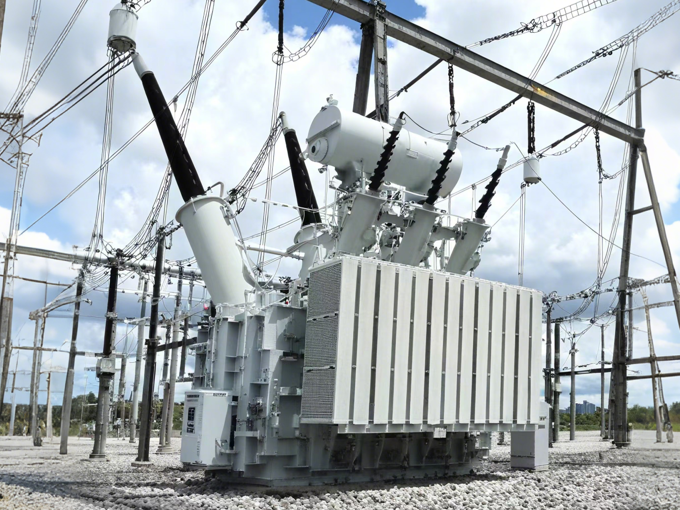
Comparing power-transformer energy losses only by looking at one supplier's “efficiency” percentage can lead to a poor purchasing decision. Two transformers with the same MVA rating may have very different no-load losses, load losses, temperature characteristics, and lifecycle energy costs. A transformer with a lower purchase price can ultimately cost more if it consumes significantly more electricity throughout its operating life. Buyers should compare power-transformer energy losses by separating no-load loss and load loss, verifying that all suppliers use comparable test conditions, applying the losses to the project's actual load profile and energized hours, and converting the resulting energy consumption into lifecycle cost.
The transformer with the lowest purchase price is normally the most economical choice.False
Initial price is only one part of transformer lifecycle cost. Higher no-load and load losses can create substantial electricity expenses over many years of operation.
What Loss Values Should Buyers Compare?
The first step is to separate transformer losses into their main categories.
| Loss Parameter | Main Cause | How It Changes | Why Buyers Should Care |
|---|---|---|---|
| No-load loss | Core hysteresis and eddy currents | Mainly continuous when energized | Important for 24/7 operation |
| Load loss | Winding resistance and related effects | Increases approximately with current² | Important at medium and high loading |
| Stray load loss | Leakage flux and induced currents | Increases with loading | Important for large transformers |
| Auxiliary consumption | Fans, pumps, controls | Depends on cooling system | Affects net efficiency |
| Total loss | Combination of losses | Depends on operating condition | Used for lifecycle comparison |
For most standard procurement specifications, guaranteed no-load loss and guaranteed load loss should be the primary comparison values.
Why Should No-Load Loss Be Compared Separately?
No-load loss occurs whenever the transformer is energized, even when the useful load is very small.
This makes it especially important for transformers that remain connected to the system continuously.
For example, assume two transformers have:
- Transformer A: 5 kW no-load loss
- Transformer B: 3 kW no-load loss
The difference is only 2 kW.
But over 8,760 energized hours per year:
2 kW × 8,760 = 17,520 kWh/year
Over 20 years, the difference could reach approximately:
350,400 kWh
before considering changes in loading, electricity prices, or discounting.
Therefore, buyers should not dismiss a 1–2 kW difference in no-load loss simply because it appears small compared with the transformer's MVA rating.
How Should Buyers Compare Load Loss?
Load loss behaves differently.
It increases strongly with transformer current and is approximately proportional to the square of current under simplified conditions.
For example:
| Loading | Approximate Relative Load Loss |
|---|---|
| 25% | 6.25% |
| 50% | 25% |
| 75% | 56.25% |
| 100% | 100% |
| 110% | 121% |
These figures illustrate the I² relationship and are not substitutes for factory test results.
This means that a transformer operating heavily loaded for many hours can benefit substantially from lower guaranteed load loss.
A transformer serving a lightly loaded facility may place greater economic value on low no-load loss.
Should Buyers Compare Losses at the Same Temperature?
Yes.
This is a critical but sometimes overlooked issue.
Winding resistance changes with conductor temperature, so load-loss values must be associated with a defined reference temperature.
If Supplier A quotes load loss at one reference temperature and Supplier B uses another, their values may not be directly comparable.
A procurement specification should therefore identify:
- Reference temperature
- Rated current
- Measurement method
- Applicable standard
- Guaranteed tolerance
- Correction method where applicable
Comparable test conditions are essential for a fair supplier comparison.
How Does the Actual Load Profile Change the Decision?
The transformer's nameplate rating does not tell buyers how much energy the transformer will actually lose.
Consider two identical 10 MVA transformers.
Transformer A operates at:
- 20% load for most of the year
- 50% load during daytime
- 80% load for short periods
Transformer B operates at:
- 70–90% load for most of the year
The economic value of low no-load loss versus low load loss will be different for these two projects.
Therefore, buyers should provide suppliers with an estimated load-duration curve or at least representative loading percentages and operating hours.
How Can Buyers Calculate Annual Energy Loss?
A simplified calculation can be made using the no-load loss and load loss.
For a transformer with:
- No-load loss = 4 kW
- Full-load loss = 20 kW
- 8,760 energized hours/year
At 50% loading, the approximate load loss is:
20 × 0.5² = 5 kW
Therefore:
Total loss ≈ 4 + 5 = 9 kW
Annual energy loss would be approximately:
9 × 8,760 = 78,840 kWh/year
For variable loading, the calculation should be performed for each loading period rather than using one average percentage.
Why Is Lifecycle Cost More Useful Than Purchase Price?
A transformer can remain in service for decades.
Consequently, buyers should consider:
Initial purchase price + installation cost + energy-loss cost + maintenance cost + replacement cost
For example:
| Item | Transformer A | Transformer B |
|---|---|---|
| Purchase price | $100,000 | $108,000 |
| No-load loss | 5 kW | 3.5 kW |
| Full-load loss | 22 kW | 17 kW |
| Initial investment | Lower | Higher |
| Energy performance | Lower | Higher |
Transformer B costs $8,000 more initially, but its lower losses may generate enough energy savings to recover that additional investment.
The correct answer depends on the actual loading profile and electricity tariff.
How Does Electricity Price Affect Transformer Selection?
The value of lower losses increases as electricity prices increase.
Suppose two transformers have a calculated annual loss-energy difference of 30,000 kWh.
At an illustrative electricity cost of:
- $0.05/kWh → $1,500/year
- $0.10/kWh → $3,000/year
- $0.15/kWh → $4,500/year
- $0.20/kWh → $6,000/year
The same technical loss difference therefore has very different economic value in different markets.
For long-term projects, buyers should use the expected electricity tariff or an appropriate range of future energy prices rather than relying on one arbitrary value.
Should Buyers Compare Total Loss at Rated Load?
Yes, but not exclusively.
Rated-load total loss provides a useful reference for comparing transformer designs under full-load conditions.
However, many transformers do not operate continuously at rated load.
A transformer with excellent full-load performance may not be the most economical choice if it spends most of its life at 20–40% loading and remains energized continuously.
The comparison should therefore include:
- No-load loss
- Load loss
- Total loss at relevant loading points
- Annual loss energy
- Lifecycle loss cost
What About Transformer Oversizing?
Oversizing can reduce current-dependent losses because the transformer operates at a lower percentage of its rated capacity.
However, a larger transformer does not automatically produce lower total lifecycle cost.
A larger unit can involve:
- Higher purchase price
- Greater physical dimensions
- More material
- Different no-load loss
- Higher installation cost
Buyers should therefore compare the complete lifecycle economics, not assume that a larger MVA rating is inherently more efficient.
How Should Buyers Handle Auxiliary Power?
Large transformers may use:
- Cooling fans
- Oil pumps
- Control systems
- Monitoring equipment
These systems consume electricity.
For a large forced-cooled transformer, auxiliary consumption can therefore become relevant when calculating net operating efficiency.
Buyers should ask suppliers to identify auxiliary power requirements under the applicable cooling modes.
This is especially useful when comparing:
Natural cooling versus forced cooling
or different cooling-system configurations.
How Can Buyers Verify Supplier Loss Claims?
Loss values should not be accepted solely from a commercial quotation.
Buyers should request appropriate factory documentation, including:
- Routine test reports
- Type-test information where relevant
- Guaranteed loss values
- Applicable standards
- Measurement conditions
- Temperature reference
- Test tolerances
For large or critical transformers, buyers may also specify witnessed factory acceptance testing.
This provides stronger contractual evidence that the supplied transformer meets the guaranteed performance.
What Contract Terms Should Protect Buyers?
Energy-loss requirements should be contractual rather than merely descriptive.
The purchase contract should clearly state:
- Guaranteed no-load loss
- Guaranteed load loss
- Reference temperature
- Test standard
- Acceptance method
- Permitted tolerances
- Factory testing procedure
- Treatment of measured loss exceeding the guarantee
- Commercial remedy or price adjustment
- Responsibility for retesting
For major projects, buyers can consider contractual loss penalties or price adjustments if measured losses exceed guaranteed values.
This creates an incentive for the supplier to deliver the specified design performance.
What Is a Practical Transformer Loss Comparison Method?
A useful buyer workflow is:
Step 1: Confirm that all suppliers meet the same electrical specification.
Step 2: Compare guaranteed no-load losses.
Step 3: Compare guaranteed load losses at the same reference temperature.
Step 4: Apply each loss value to the actual project loading profile.
Step 5: Calculate annual kWh lost.
Step 6: Convert annual losses into monetary cost.
Step 7: Calculate lifecycle cost using the expected service period.
Step 8: Verify guarantees through factory testing and contractual remedies.
This approach prevents a low initial quotation from appearing artificially attractive.
How Can Power Transformer Design Reduce Energy Losses and Lifecycle Costs?
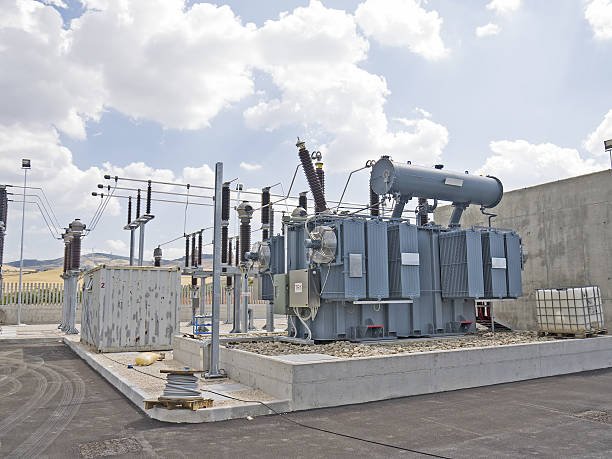
Power transformer losses are often treated as unavoidable operating expenses, but good engineering design can reduce them significantly over the transformer's service life. Choosing a transformer only by MVA capacity and initial purchase price can overlook the long-term cost of core loss, winding loss, cooling power, and heat-related aging. Power transformer design can reduce energy losses and lifecycle costs by optimizing the magnetic core, winding conductors, flux density, leakage-flux control, cooling system, impedance, and operating capacity for the actual load profile. The most economical design balances initial material and manufacturing costs against decades of energy savings, thermal performance, maintenance requirements, and service life.
Reducing transformer losses always requires substantially increasing the purchase price.False
Some loss reductions require higher-quality materials or additional design optimization, but improved core joints, conductor arrangement, cooling design, manufacturing control, and appropriate capacity selection can also reduce losses without proportionally increasing total cost.
Which Design Factors Have the Greatest Influence on Transformer Losses?
The two primary design targets are core loss and load loss.
Core loss is mainly associated with hysteresis and eddy currents in the magnetic core and exists whenever the transformer is energized. Load loss is primarily associated with winding resistance and stray effects and increases substantially with current.
| Design Area | Main Loss Influenced | Design Approach | Lifecycle Benefit |
|---|---|---|---|
| Core material | No-load loss | High-quality electrical steel | Lower continuous energy consumption |
| Core joints | No-load loss | Optimized joint construction | Reduced localized core losses |
| Flux density | Core loss | Appropriate magnetic operating point | Better efficiency |
| Conductors | Load loss | Suitable cross-section and material | Lower I²R losses |
| Winding geometry | Load/stray loss | Optimized conductor arrangement | Lower heating |
| Leakage-flux control | Stray loss | Electromagnetic optimization | Reduced structural heating |
| Cooling system | Thermal/auxiliary loss | Correct cooling configuration | Lower temperature and auxiliary consumption |
| Capacity selection | Overall losses | Match rating to load profile | Better lifecycle economics |
The important point is that these elements interact. Improving one component while neglecting another may produce limited overall benefit.
How Can Core Design Reduce No-Load Losses?
The magnetic core is one of the most important areas for efficiency improvement.
Modern power transformers commonly use grain-oriented electrical steel with controlled magnetic properties. The core is constructed from thin laminations with insulation between layers to reduce circulating eddy currents.
Designers can reduce core losses by optimizing:
- Electrical-steel grade
- Lamination thickness
- Magnetic flux density
- Core-joint configuration
- Core geometry
- Grain orientation
- Cutting and assembly quality
Core joints deserve particular attention. Poorly designed or manufactured joints can create localized flux distortion and additional losses.
Therefore, buying higher-quality core steel alone is not enough. The core material, magnetic design, and manufacturing process must work together.
Can Optimizing Flux Density Reduce Energy Consumption?
Yes, but flux density must be carefully balanced.
Increasing magnetic flux density can reduce the amount of core material required for a particular design, potentially reducing transformer size and material cost. However, excessive flux density can increase core losses and may push the core toward undesirable magnetic operating conditions.
Conversely, designing with unnecessarily low flux density may reduce core loss but require a larger and potentially more expensive core.
The objective is therefore not simply “minimum flux density,” but an economically optimized operating point.
This is a typical transformer-design tradeoff:
Core material cost ↔ transformer size ↔ core loss ↔ lifecycle energy cost
How Can Winding Design Reduce Load Losses?
Winding design directly affects current-dependent losses.
The basic relationship is:
[P_{\text{load}}\approx I^2R]
Therefore, designers can reduce resistive losses by optimizing conductor resistance.
Important measures include:
- Appropriate conductor cross-section
- Suitable copper or aluminum selection
- Lower current density
- Optimized winding length
- Reduced connection resistance
- Efficient conductor arrangement
- Appropriate winding geometry
However, using larger conductors indefinitely is not economical. More conductor material increases transformer cost and weight.
The best design finds the point at which additional conductor investment produces worthwhile lifetime energy savings.
How Does Winding Geometry Influence Stray Loss?
Not all winding-related losses are simple DC resistance losses.
Leakage flux can induce additional currents in conductors and nearby metallic components, producing stray losses and localized heating.
Advanced transformer design therefore considers electromagnetic field distribution.
Designers can optimize:
- Winding arrangement
- Conductor transposition
- Radial and axial geometry
- Leakage-flux distribution
- Tank shielding
- Structural-component placement
Reducing stray flux can improve efficiency while also reducing localized hot spots.
This is particularly important for large power transformers because even relatively small additional losses can become significant at high MVA ratings.
How Does Cooling Design Reduce Lifecycle Cost?
Cooling does not directly eliminate the losses generated by the transformer, but it determines how effectively those losses can be removed.
A poorly matched cooling system can cause excessive temperature rise, while an unnecessarily large forced-cooling system may consume additional auxiliary energy.
Designers therefore need to balance:
Heat generation + heat transfer + cooling energy + required thermal margin
For liquid-filled transformers, this may involve optimizing radiators, oil circulation, fans, pumps, and heat exchangers.
For dry-type transformers, airflow, ventilation passages, winding geometry, and room conditions are particularly important.
An efficient cooling design should maintain acceptable temperatures without consuming unnecessary auxiliary power.
How Does Transformer Capacity Affect Lifecycle Cost?
Capacity selection is one of the most important economic design decisions.
A transformer that is significantly oversized may operate at a low percentage of its rated capacity for most of its life. This can increase the relative importance of no-load loss.
An undersized transformer may experience high loading, increasing winding losses and temperature.
The objective is therefore to select capacity based on:
- Present demand
- Expected load growth
- Peak demand
- Average loading
- Load-duration curve
- Short-term overload requirements
- Future expansion plans
The best transformer capacity is not necessarily the largest practical unit. It is the rating that provides sufficient operational margin while maintaining an economically appropriate loss profile.
How Can Buyers Evaluate the Design Before Purchase?
Buyers should request technical information that allows the design to be evaluated on a lifecycle basis.
Important data include:
- Rated MVA
- No-load loss
- Load loss
- Impedance
- Temperature rise
- Cooling method
- Core material
- Winding material
- Reference temperature for load loss
- Auxiliary power consumption
- Guaranteed efficiency where applicable
A supplier should also clearly identify the applicable testing and acceptance requirements.
For major projects, factory testing can verify whether the delivered transformer actually achieves the guaranteed loss values.
How Can Design Reduce Lifecycle Cost Without Excessive Initial Investment?
The key is economic optimization rather than maximum specification.
For example, a buyer may have two options:
| Parameter | Standard Design | Optimized Low-Loss Design |
|---|---|---|
| Initial price | Lower | Higher |
| No-load loss | Higher | Lower |
| Load loss | Higher | Lower |
| Heat generation | Higher | Lower |
| Cooling demand | Higher | Lower |
| Long-term energy cost | Higher | Lower |
| Expected lifecycle cost | Potentially higher | Potentially lower |
The optimized design is worthwhile when the additional initial investment is recovered through energy savings and other lifecycle benefits.
This is why a total cost of ownership approach is more useful than simply comparing purchase quotations.
What Role Does Manufacturing Quality Play?
Design calculations only represent the intended transformer performance.
Manufacturing quality determines whether that performance is actually achieved.
Important production controls include:
- Core cutting accuracy
- Lamination handling
- Core-joint quality
- Winding dimensional accuracy
- Conductor insulation
- Winding tension
- Drying and vacuum treatment
- Assembly precision
- Connection quality
- Final testing
A high-grade design manufactured poorly may perform worse than a simpler design manufactured consistently.
Therefore, buyers should evaluate both engineering capability and manufacturing quality when selecting a transformer supplier.
Conclusion
Energy losses have a direct influence on power transformer efficiency, operating temperature, maintenance requirements, and total cost of ownership. Core losses occur continuously while the transformer is energized, whereas load losses vary with operating current and can become particularly significant at high loads. Buyers should therefore consider both loss categories when comparing transformer designs and should evaluate efficiency alongside capacity, loading patterns, cooling requirements, and expected service life. Selecting a low-loss, appropriately designed transformer can reduce wasted energy, control thermal stress, and deliver significant lifecycle savings while improving long-term power system reliability.
FAQ
Q1: What are energy losses in power transformers?
Energy losses in power transformers are the electrical energy converted into heat or other forms of energy during the transformation and transmission of electrical power. No transformer can operate with zero losses, but good design and material selection can significantly reduce them.
Transformer losses are generally divided into no-load losses and load losses.
No-load losses occur whenever the transformer is energized, even when it is not supplying significant electrical power. They mainly come from the magnetic core and include hysteresis and eddy-current losses.
Load losses increase as current flows through the windings. They are primarily associated with winding resistance and additional stray losses caused by leakage magnetic fields interacting with conductive transformer components.
The distinction is important because the two types of losses behave differently.
No-load losses remain relatively stable as the transformer's load changes. A transformer that remains energized continuously therefore accumulates these losses throughout its operating life.
Load losses, by contrast, increase significantly with load current. As a general relationship, winding-related losses are approximately proportional to the square of current. This means that operating a transformer at high load can cause losses to rise rapidly.
Energy losses affect several aspects of transformer performance:
Overall efficiency
Operating temperature
Electricity consumption
Cooling requirements
Available capacity
Insulation aging
Service life
Lifecycle cost
For example, excessive losses produce additional heat. If the cooling system cannot remove that heat effectively, the transformer's temperature rises. Higher temperatures can accelerate insulation aging and potentially reduce service life.
This is why transformer procurement specifications normally include guaranteed loss values. Buyers should evaluate both no-load and load losses rather than relying only on the transformer's rated capacity or efficiency percentage.
A transformer with a slightly higher purchase price can sometimes provide better long-term value if its lower losses produce substantial energy savings over decades of operation.
Q2: How do core losses and load losses differ?
Core losses and load losses are different in both their causes and their relationship to transformer loading.
Core losses, also called no-load losses, occur because the transformer core is repeatedly magnetized and demagnetized whenever the transformer is energized. They mainly consist of hysteresis loss and eddy-current loss.
Core losses depend on factors such as:
Core material
Magnetic flux density
Operating frequency
Lamination thickness
Core construction
They remain present even when the transformer has little or no external load.
Load losses are associated mainly with the current flowing through the transformer windings and other components affected by leakage flux.
The main winding component is commonly represented by copper or conductor resistance. As current increases, resistive losses increase approximately with the square of current.
For example, if current doubles, the resistive component of load loss can increase by approximately four times under comparable conditions.
Load losses can also include stray losses in:
Windings
Tank walls
Structural components
Clamping components
The difference has important implications for transformer selection.
If a transformer is energized continuously but frequently operates at light load, reducing core losses can be particularly valuable.
If a transformer operates close to full load for long periods, reducing load losses becomes increasingly important.
Therefore, buyers should evaluate transformer losses using the project's actual load profile rather than selecting equipment solely according to a single efficiency percentage.
A useful procurement evaluation can include:
Loss Type Main Cause Dependence on Load
No-load loss Core magnetization Relatively independent
Load loss Winding resistance and stray effects Increases with load
Total loss Combination of both Changes with operating point
Understanding this distinction allows buyers to compare transformer designs more accurately and estimate their actual lifetime energy costs.
Q3: How do energy losses affect transformer efficiency?
Energy losses directly reduce transformer efficiency because some of the electrical power entering the transformer is dissipated rather than delivered to the load.
Transformer efficiency can be expressed conceptually as the useful output power divided by the input power. The difference between input and output represents losses.
A transformer with lower losses can deliver the same useful output while consuming less input energy. This becomes particularly important for transformers that operate continuously for many years.
However, transformer efficiency is not constant at every load level.
At very light load, no-load losses can represent a relatively large proportion of the power being transferred. As the load increases, load losses become increasingly significant.
This means a transformer may have different efficiency characteristics at:
25% load
50% load
75% load
100% load
The most efficient operating point depends on the transformer's design and loss characteristics.
For buyers, this is why a single headline efficiency figure may not tell the complete story. A more useful evaluation considers guaranteed no-load loss and load loss separately and applies them to the expected load profile.
For example, two transformers with identical MVA ratings may have different loss characteristics. One may have a lower no-load loss but higher load loss, while another may show the opposite pattern.
The better option depends on how the transformer will actually operate.
Efficiency also has a financial impact. Even a relatively small continuous loss can accumulate into a substantial amount of energy over a transformer’s service life.
Consequently, transformer efficiency should be considered as both a technical performance measure and a lifecycle cost factor.
Q4: How do energy losses affect transformer temperature and service life?
Energy losses are converted primarily into heat, making them an important factor in transformer thermal performance.
Every transformer produces heat through core losses, winding losses, and other stray losses. The transformer cooling system must transfer this heat to the surrounding environment.
If losses increase without a corresponding improvement in heat removal, operating temperatures can rise.
Higher temperatures can affect:
Insulation aging
Winding temperature
Oil or resin temperature
Mechanical stress
Cooling-system requirements
Long-term reliability
For liquid-immersed transformers, the insulating and cooling fluid transfers heat away from the windings and core toward radiators, heat exchangers, or other cooling equipment.
For dry-type transformers, heat must be transferred through the solid insulation system and surrounding air, making ventilation and ambient conditions particularly important.
Temperature is especially significant because insulation generally ages faster at elevated operating temperatures. Excessive thermal stress over long periods can shorten the useful life of the insulation system.
This creates a connection between energy efficiency and reliability:
Lower losses → less heat generation → lower thermal stress → potentially longer insulation life.
However, transformer life is influenced by many other factors, including moisture, overloads, electrical disturbances, mechanical stresses, environmental conditions, and maintenance quality.
Therefore, reducing energy losses does not automatically guarantee a specific service life, but it can contribute to better thermal performance and reduced operating stress.
When selecting a transformer, buyers should therefore review both guaranteed losses and temperature-rise requirements.
References
IEC 60076 – Power Transformers
https://webstore.iec.ch/en/publication/602
IEC 60076-1 – Power Transformers: General
https://webstore.iec.ch/en/publication/603
IEC 60076-11 – Power Transformers: Dry-Type Transformers
https://webstore.iec.ch/en/publication/604
IEEE C57 Series – Transformer Standards
https://standards.ieee.org
U.S. Department of Energy – Transformer Efficiency Resources
https://www.energy.gov
U.S. Department of Energy – Distribution Transformer Energy Efficiency
https://www.energy.gov/articles/doe-finalizes-energy-efficiency-standards-distribution-transformers-protect-domestic
NEMA – Electrical Standards and Products
https://www.nema.org