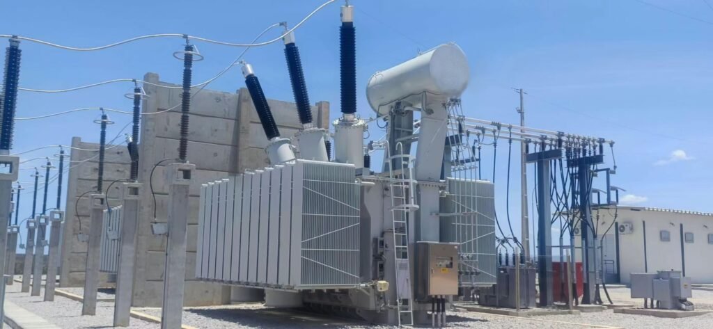
Impedance is one of the most important electrical characteristics of a transformer, affecting voltage regulation, fault current levels, load sharing, and overall system performance. Although it is often expressed as a percentage on the transformer nameplate, impedance represents the transformer’s opposition to alternating current flow under load conditions. Understanding transformer impedance is essential for proper system design, protection coordination, and reliable operation.
What Is Transformer Impedance?
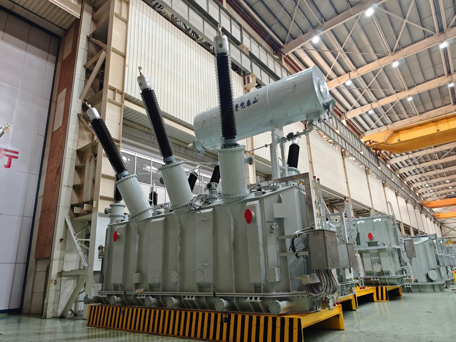
Transformer impedance is one of the most important electrical characteristics in transformer engineering because it directly affects voltage regulation, fault current limitation, power system protection, load sharing, transformer efficiency, and operational reliability. In every power transformer, impedance determines how the transformer behaves under both normal operating conditions and abnormal fault conditions. Electrical engineers pay close attention to transformer impedance because even a small change in impedance can significantly influence the stability and safety of an entire power system.
Unlike simple resistance in DC circuits, transformer impedance in AC systems consists of both resistance and reactance. Resistance causes heating and energy losses inside transformer windings, while reactance limits alternating current flow and controls short-circuit current levels. Together, these two components form the total impedance of the transformer. During transformer design, manufacturers carefully balance impedance values to ensure safe fault protection, acceptable voltage regulation, stable parallel operation, and efficient electrical performance.
Transformer impedance is usually expressed as a percentage called percent impedance or impedance voltage. This value indicates how much voltage is required to circulate full-load current through the transformer when the secondary winding is short-circuited. Although this may seem like a purely technical parameter, impedance has major practical importance because it affects everything from circuit breaker sizing to transformer mechanical strength.
Transformer impedance is the total opposition that a transformer presents to alternating current flow, consisting of winding resistance and leakage reactance, which together control short-circuit current, voltage regulation, load sharing, fault protection, and transformer operating performance.
Transformer impedance plays a central role in modern electrical systems including utility substations, industrial facilities, renewable energy networks, railway electrification systems, and power transmission infrastructure.
Transformer impedance only refers to winding resistance and does not significantly affect transformer protection or fault current.False
Transformer impedance includes both resistance and reactance, and it strongly influences short-circuit current limitation, voltage regulation, system protection, and transformer mechanical stress during faults.
Why Transformer Impedance Is Important
Transformer impedance affects nearly every aspect of transformer operation.
Main Functions of Transformer Impedance
| Function | Importance |
|---|---|
| Short-circuit current limitation | System protection |
| Voltage regulation | Stable power supply |
| Load sharing | Parallel transformer operation |
| Mechanical stress reduction | Transformer durability |
| Fault coordination | Protection reliability |
Without proper impedance values, transformers could experience excessive fault current, unstable voltage, or severe mechanical damage.
Basic Meaning of Transformer Impedance
Transformer impedance is the total opposition to alternating current flow inside the transformer.
Components of Transformer Impedance
Transformer impedance contains two primary electrical components:
| Component | Function |
|---|---|
| Resistance (R) | Produces heat and energy loss |
| Reactance (X) | Limits alternating current flow |
Together, resistance and reactance form the total AC impedance.
Transformer Impedance Equation
Z=R+jX
Where:
- (Z) = total impedance
- (R) = resistance
- (X) = reactance
- (j) = imaginary operator in AC analysis
In most power transformers, reactance is much larger than resistance.
What Creates Transformer Impedance?
Transformer impedance is produced by internal transformer construction and electromagnetic behavior.
Sources of Transformer Resistance
Resistance mainly comes from transformer winding conductors.
| Source | Effect |
|---|---|
| Copper winding resistance | Heating losses |
| Aluminum conductor resistance | Additional power loss |
| Connection resistance | Minor voltage drop |
Resistance Formula
R=\rho\frac{L}{A}
Where:
- (R) = resistance
- (\rho) = conductor resistivity
- (L) = conductor length
- (A) = conductor cross-sectional area
Longer conductors increase resistance, while larger conductor area reduces resistance.
Sources of Transformer Reactance
Reactance is mainly caused by leakage magnetic flux.
| Source | Result |
|---|---|
| Leakage flux | Leakage reactance |
| Incomplete magnetic coupling | Current limitation |
| Magnetic field storage | Reactive energy |
Not all magnetic flux produced by the primary winding links perfectly with the secondary winding. The unused portion creates leakage reactance.
What Is Leakage Reactance?
Leakage reactance is one of the most important parts of transformer impedance.
How Leakage Flux Occurs
Some magnetic flux travels outside the intended magnetic path between windings.
| Magnetic Flux Type | Function |
|---|---|
| Mutual flux | Transfers energy |
| Leakage flux | Produces reactance |
Leakage reactance helps limit short-circuit current during fault conditions.
Percent Impedance in Transformers
Transformer impedance is commonly expressed as percent impedance.
Definition of Percent Impedance
Percent impedance is the percentage of rated voltage required to circulate full-load current during a short-circuit test.
Percent Impedance Formula
Z%=\frac{V{sc}}{V{rated}}\times100
Where:
- (Z%) = percent impedance
- (V_{sc}) = short-circuit voltage
- (V_{rated}) = rated transformer voltage
Typical Transformer Impedance Values
Different transformers use different impedance ranges.
Common Impedance Ranges
| Transformer Type | Typical Impedance |
|---|---|
| Distribution transformer | 4%–6% |
| Power transformer | 6%–15% |
| Furnace transformer | 10%–20% |
| Generator transformer | 8%–18% |
Larger transformers generally use higher impedance values to limit fault current.
Transformer Impedance and Short-Circuit Current
One of the most critical functions of transformer impedance is fault current limitation.
Short-Circuit Current Relationship
Fault current is inversely proportional to transformer impedance.
Short-Circuit Current Equation
I{sc}=\frac{I{rated}}{Z_{pu}}
Where:
- (I_{sc}) = short-circuit current
- (I_{rated}) = rated current
- (Z_{pu}) = per-unit impedance
Lower impedance allows higher fault current.
Effects of Low Transformer Impedance
Advantages of Low Impedance
| Advantage | Benefit |
|---|---|
| Better voltage regulation | Stable output voltage |
| Lower voltage drop | Improved efficiency |
Disadvantages of Low Impedance
| Disadvantage | Problem |
|---|---|
| Higher fault current | Increased mechanical stress |
| Greater short-circuit force | Protection challenges |
Effects of High Transformer Impedance
Advantages of High Impedance
| Advantage | Benefit |
|---|---|
| Lower fault current | Improved protection |
| Reduced mechanical stress | Better fault survival |
Disadvantages of High Impedance
| Disadvantage | Problem |
|---|---|
| Higher voltage drop | Poor voltage regulation |
| Reduced load performance | Lower system stability |
Transformer manufacturers must carefully balance these competing factors.
Transformer Impedance and Voltage Regulation
Transformer impedance directly influences voltage regulation.
What Is Voltage Regulation?
Voltage regulation measures the voltage difference between no-load and full-load operation.
Voltage Regulation Formula
VR%=\frac{V{NL}-V{FL}}{V_{FL}}\times100
Where:
- (VR%) = voltage regulation
- (V_{NL}) = no-load voltage
- (V_{FL}) = full-load voltage
Impedance and Voltage Drop Relationship
| Impedance Level | Voltage Regulation |
|---|---|
| Lower impedance | Better regulation |
| Higher impedance | Larger voltage drop |
Distribution transformers often use lower impedance to maintain stable customer voltage.
Transformer Impedance in Parallel Operation
Transformers frequently operate in parallel to increase system reliability and capacity.
Benefits of Parallel Operation
| Benefit | Purpose |
|---|---|
| Increased load capacity | Higher power support |
| Backup capability | Improved reliability |
| Maintenance flexibility | Reduced downtime |
Importance of Matching Impedance
Parallel transformers must have similar impedance values.
Problems Caused by Unequal Impedance
| Problem | Consequence |
|---|---|
| Unequal load sharing | Overloading risk |
| Circulating current | Additional losses |
| Protection instability | Relay coordination problems |
Mechanical Stress During Fault Conditions
Short-circuit currents generate powerful electromagnetic forces.
Electromagnetic Force Relationship
F\propto I^2
Where:
- (F) = electromagnetic force
- (I) = fault current
Higher fault current creates dramatically larger mechanical forces.
Why Impedance Protects Transformer Windings
Higher impedance reduces short-circuit current and lowers mechanical stress.
Mechanical Protection Benefits
| Benefit | Result |
|---|---|
| Reduced fault current | Lower winding deformation |
| Reduced electromagnetic force | Improved transformer lifespan |
Transformer Losses and Impedance
Transformer impedance also affects efficiency and thermal performance.
Copper Losses
Winding resistance causes copper losses.
Copper Loss Equation
P_{cu}=I^2R
Where:
- (P_{cu}) = copper loss
- (I) = current
- (R) = winding resistance
High current significantly increases transformer heating.
Reactive Power and Reactance
Reactance influences reactive power flow in AC systems.
Reactive Power Equation
Q=VI\sin\phi
Where:
- (Q) = reactive power
- (V) = voltage
- (I) = current
- (\phi) = phase angle
Transformer Impedance Testing
Manufacturers test transformer impedance during factory production.
Short-Circuit Test Procedure
| Test Step | Purpose |
|---|---|
| Secondary winding shorted | Simulated fault condition |
| Reduced voltage applied | Rated current circulation |
| Voltage measured | Impedance calculation |
Importance of Impedance Testing
| Purpose | Benefit |
|---|---|
| Verify design accuracy | Quality assurance |
| Confirm protection coordination | System compatibility |
| Validate performance | Operational safety |
Transformer Impedance in Different Applications
Different applications require different impedance characteristics.
Distribution Transformers
| Requirement | Reason |
|---|---|
| Low impedance | Better voltage regulation |
| Moderate fault limitation | Residential reliability |
Power Transformers
| Requirement | Reason |
|---|---|
| Moderate-to-high impedance | Fault current limitation |
| System stability | Grid protection |
Furnace Transformers
| Requirement | Reason |
|---|---|
| High impedance | Extreme current control |
| Arc stability | Industrial process protection |
Factors Affecting Transformer Impedance
Several design parameters determine impedance value.
Main Design Factors
| Design Factor | Influence |
|---|---|
| Winding spacing | Leakage reactance |
| Conductor size | Resistance |
| Core structure | Magnetic coupling |
| Winding arrangement | Current limitation |
Winding Geometry Effects
Increasing the distance between windings increases leakage reactance.
Winding Distance Relationship
| Winding Distance | Reactance Level |
|---|---|
| Small spacing | Lower reactance |
| Larger spacing | Higher reactance |
Impedance and Power System Protection
Protection engineers rely heavily on transformer impedance data.
Protection Applications
| Application | Purpose |
|---|---|
| Fault current calculation | Circuit breaker sizing |
| Relay coordination | Selective protection |
| Arc flash analysis | Personnel safety |
Smart Transformers and Impedance Monitoring
Modern transformers increasingly use intelligent monitoring systems.
Smart Monitoring Functions
| Parameter | Purpose |
|---|---|
| Impedance variation | Fault detection |
| Thermal behavior | Temperature protection |
| Harmonic distortion | Power quality analysis |
Future Trends in Transformer Impedance Technology
| Technology | Future Benefit |
|---|---|
| Smart transformers | Real-time impedance monitoring |
| AI diagnostics | Predictive maintenance |
| Digital substations | Automated system analysis |
Key Characteristics of Transformer Impedance
| Characteristic | Importance |
|---|---|
| Limits fault current | System protection |
| Controls voltage regulation | Stable operation |
| Influences load sharing | Parallel operation |
| Reduces mechanical stress | Transformer durability |
| Affects efficiency | Energy performance |
How Is Transformer Impedance Measured and Expressed?
Transformer impedance is one of the most important electrical parameters used in transformer design, testing, protection coordination, and power system analysis. It determines how much a transformer resists alternating current flow during normal operation and fault conditions. Because transformer impedance directly affects short-circuit current, voltage regulation, load sharing, system stability, and transformer mechanical stress, accurate impedance measurement is essential during transformer manufacturing and commissioning.
In practical transformer engineering, impedance is not measured by simply using an ohmmeter because transformers operate in AC systems where both resistance and reactance exist simultaneously. Instead, transformer impedance is measured through a controlled short-circuit test in which one winding is shorted while a reduced voltage is applied to the other winding until rated current flows through the transformer. The voltage required to produce rated current under this condition represents the transformer impedance voltage.
Transformer impedance is typically expressed as percent impedance (%Z), per-unit impedance (pu), or impedance voltage. These standardized expressions allow engineers to compare transformers of different sizes and voltage ratings more easily. Percent impedance is especially important because it directly indicates the transformer’s ability to limit short-circuit current and maintain voltage regulation.
Transformer impedance is measured using a short-circuit test where rated current is circulated through the transformer under controlled conditions, and it is commonly expressed as percent impedance, per-unit impedance, or impedance voltage to represent the transformer’s opposition to alternating current flow.
Accurate impedance measurement is critical for transformer quality assurance, protection system coordination, parallel transformer operation, and electrical network safety.
Transformer impedance can be accurately measured using a standard DC resistance meter without applying AC current or performing short-circuit testing.False
Transformer impedance includes both resistance and reactance, so it must be measured using AC short-circuit testing rather than simple DC resistance measurement.
Why Transformer Impedance Measurement Is Important
Transformer impedance affects multiple aspects of electrical system operation.
Main Reasons for Measuring Transformer Impedance
| Purpose | Importance |
|---|---|
| Short-circuit current calculation | Protection coordination |
| Voltage regulation analysis | System stability |
| Parallel transformer operation | Load sharing |
| Manufacturing quality verification | Performance validation |
| Fault analysis | Operational safety |
Without accurate impedance data, power system design and protection become unreliable.
What Is Transformer Impedance?
Transformer impedance is the total opposition to AC current flow.
Components of Transformer Impedance
| Component | Function |
|---|---|
| Resistance (R) | Produces heat and copper loss |
| Reactance (X) | Limits alternating current flow |
Together, resistance and reactance form total impedance.
Transformer Impedance Equation
Z=R+jX
Where:
- (Z) = total impedance
- (R) = resistance
- (X) = reactance
- (j) = imaginary operator
In most power transformers, reactance is much larger than resistance.
Why AC Testing Is Necessary
Transformer impedance cannot be measured accurately with DC measurement alone.
Difference Between Resistance and Impedance
| Parameter | DC or AC |
|---|---|
| Resistance | DC property |
| Impedance | AC property |
Reactance only exists in alternating current systems.
Transformer Short-Circuit Test
The most common method of measuring transformer impedance is the short-circuit test.
Basic Short-Circuit Test Principle
One winding is shorted while reduced voltage is applied to the other winding.
Main Test Steps
| Step | Description |
|---|---|
| Secondary winding shorted | Simulated fault condition |
| Reduced voltage applied to primary | Controlled current flow |
| Voltage increased gradually | Rated current achieved |
| Applied voltage recorded | Impedance calculation |
The applied voltage required to circulate rated current represents the transformer impedance voltage.
Why Reduced Voltage Is Used
Only a small percentage of rated voltage is needed during impedance testing.
Typical Test Voltage Range
| Transformer Type | Typical Short-Circuit Voltage |
|---|---|
| Distribution transformer | 4%–6% |
| Power transformer | 6%–15% |
| Large generator transformer | 10%–18% |
Because the secondary winding is shorted, only a small voltage is needed to produce full-load current.
Percent Impedance Expression
Transformer impedance is most commonly expressed as percent impedance.
Definition of Percent Impedance
Percent impedance indicates the percentage of rated voltage required to circulate rated current during a short-circuit condition.
Percent Impedance Formula
Z%=\frac{V{sc}}{V{rated}}\times100
Where:
- (Z%) = percent impedance
- (V_{sc}) = short-circuit test voltage
- (V_{rated}) = rated transformer voltage
Example of Percent Impedance
If a 10kV transformer requires 500V to circulate rated current during the short-circuit test:
Example Calculation
Z%=\frac{500}{10000}\times100=5%
The transformer therefore has 5% impedance.
What Percent Impedance Means Physically
Percent impedance directly relates to fault current limitation.
Impedance and Fault Current Relationship
I{sc}=\frac{I{rated}}{Z_{pu}}
Where:
- (I_{sc}) = short-circuit current
- (I_{rated}) = rated current
- (Z_{pu}) = per-unit impedance
Lower impedance results in higher short-circuit current.
Per-Unit Impedance System
Large power systems often use the per-unit system.
What Is Per-Unit Impedance?
Per-unit impedance expresses impedance as a decimal relative to a selected base value.
Per-Unit Formula
Z_{pu}=\frac{Z%}{100}
For example:
| Percent Impedance | Per-Unit Value |
|---|---|
| 5% | 0.05 pu |
| 10% | 0.10 pu |
| 15% | 0.15 pu |
The per-unit system simplifies power system calculations significantly.
Ohmic Impedance Expression
Transformer impedance can also be expressed in ohms.
Ohmic Impedance Formula
Z=\frac{V}{I}
Where:
- (Z) = impedance in ohms
- (V) = voltage
- (I) = current
However, percent impedance is more practical for comparing transformers of different ratings.
Why Percent Impedance Is Preferred
Percent impedance provides standardized comparison independent of transformer size.
Advantages of Percent Impedance
| Advantage | Benefit |
|---|---|
| Standardized comparison | Easier engineering analysis |
| Simplified fault calculations | Protection design |
| Better system coordination | Parallel operation |
Transformer Impedance Test Equipment
Specialized electrical equipment is used during impedance testing.
Common Test Equipment
| Equipment | Function |
|---|---|
| AC power source | Supplies test voltage |
| Voltmeter | Measures applied voltage |
| Ammeter | Measures test current |
| Power analyzer | Measures power loss |
Test Conditions and Standards
Transformer impedance tests follow strict international standards.
Common Transformer Standards
| Standard | Organization |
|---|---|
| IEC 60076 | International Electrotechnical Commission |
| IEEE C57 | Institute of Electrical and Electronics Engineers |
These standards ensure consistent and accurate impedance measurements worldwide.
Resistance and Reactance Separation
Transformer impedance contains both resistance and reactance.
Impedance Triangle Relationship
Z=\sqrt{R^2+X^2}
Where:
- (Z) = impedance
- (R) = resistance
- (X) = reactance
Measuring Transformer Resistance
DC resistance tests measure winding resistance separately.
Resistance Test Purpose
| Purpose | Benefit |
|---|---|
| Winding quality verification | Manufacturing inspection |
| Loss calculation | Efficiency analysis |
Measuring Transformer Reactance
Reactance is determined indirectly using AC test data.
Reactance Calculation Formula
X=\sqrt{Z^2-R^2}
In most transformers, reactance dominates the total impedance value.
Factors Affecting Measured Impedance
Several factors influence transformer impedance measurement.
Main Influencing Factors
| Factor | Effect |
|---|---|
| Winding geometry | Leakage reactance |
| Conductor size | Resistance |
| Core design | Magnetic coupling |
| Test temperature | Resistance variation |
Temperature Influence on Resistance
Winding resistance increases with temperature.
Resistance Temperature Relationship
R_t=R_0(1+\alpha\Delta T)
Where:
- (R_t) = resistance at temperature (T)
- (R_0) = reference resistance
- (\alpha) = temperature coefficient
Transformer Impedance and Voltage Regulation
Impedance affects voltage drop under load conditions.
Voltage Regulation Formula
VR%=\frac{V{NL}-V{FL}}{V_{FL}}\times100
Where:
- (VR%) = voltage regulation
- (V_{NL}) = no-load voltage
- (V_{FL}) = full-load voltage
Higher impedance generally produces larger voltage drop.
Transformer Impedance and Mechanical Stress
Fault current creates large electromagnetic forces.
Electromagnetic Force Relationship
F\propto I^2
Higher short-circuit current produces dramatically larger mechanical force on transformer windings.
Why Impedance Matters in Protection Systems
Protection engineers use impedance data extensively.
Protection Applications
| Application | Purpose |
|---|---|
| Circuit breaker sizing | Fault interruption |
| Relay coordination | Selective protection |
| Arc flash analysis | Personnel safety |
Transformer Parallel Operation Requirements
Parallel transformers must have similar impedance values.
Problems Caused by Unequal Impedance
| Problem | Consequence |
|---|---|
| Unequal load sharing | Overloading |
| Circulating current | Additional heating |
| Reduced efficiency | Operational instability |
Smart Transformer Impedance Monitoring
Modern transformers increasingly use intelligent monitoring systems.
Smart Monitoring Functions
| Parameter | Monitoring Purpose |
|---|---|
| Impedance variation | Fault detection |
| Temperature rise | Thermal protection |
| Harmonic distortion | Power quality analysis |
Future Trends in Transformer Impedance Testing
| Technology | Future Benefit |
|---|---|
| Digital testing systems | Higher accuracy |
| AI diagnostics | Predictive analysis |
| Online impedance monitoring | Real-time condition assessment |
Key Ways Transformer Impedance Is Measured and Expressed
| Method | Description |
|---|---|
| Short-circuit test | Standard impedance measurement |
| Percent impedance | Most common expression |
| Per-unit impedance | Power system analysis |
| Ohmic impedance | Direct electrical value |
Why Is Percentage Impedance Important in Power Systems?
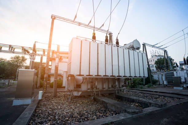
Percentage impedance is one of the most critical parameters used in transformer engineering and power system analysis because it directly affects short-circuit current, voltage regulation, system protection, fault coordination, load sharing, and overall electrical network stability. In modern power systems, transformers are interconnected with generators, transmission lines, substations, industrial loads, renewable energy systems, and distribution networks. Under these conditions, even a small difference in transformer impedance can significantly influence how electrical current flows throughout the entire system during both normal operation and fault conditions.
Transformer percentage impedance, commonly called percent impedance or %Z, represents the percentage of rated voltage required to circulate full-load current through the transformer when the secondary winding is short-circuited. Although this may appear to be a simple testing parameter, percentage impedance plays a major role in determining fault current magnitude, transformer mechanical strength, voltage drop, protection relay coordination, circuit breaker sizing, and parallel transformer operation.
In power systems, percentage impedance provides a standardized way to compare transformers with different power ratings and voltage classes. Engineers use percentage impedance because it simplifies calculations and allows accurate prediction of transformer behavior during overloads, faults, switching events, and dynamic load conditions. Low impedance improves voltage regulation but increases short-circuit current, while high impedance reduces fault current but causes larger voltage drop. Proper impedance selection therefore becomes a balance between protection, efficiency, stability, and operational reliability.
Percentage impedance is important in power systems because it determines transformer fault current limitation, voltage regulation, load sharing, protection coordination, mechanical stress resistance, and overall system stability during both normal operation and fault conditions.
Without properly selected transformer impedance values, electrical systems could experience excessive short-circuit current, unstable voltage, equipment damage, relay coordination failure, and unsafe operating conditions.
Transformer percentage impedance only affects transformer efficiency and has little influence on power system protection or fault current levels.False
Transformer percentage impedance strongly affects fault current limitation, voltage regulation, protection coordination, mechanical stress, parallel operation, and overall power system stability.
What Is Percentage Impedance?
Percentage impedance is a standardized transformer impedance expression.
Definition of Percentage Impedance
Percentage impedance represents the percentage of rated voltage required to circulate rated current through the transformer during a short-circuit condition.
Percentage Impedance Formula
Z%=\frac{V{sc}}{V{rated}}\times100
Where:
- (Z%) = percentage impedance
- (V_{sc}) = short-circuit voltage
- (V_{rated}) = rated transformer voltage
This value is usually printed directly on the transformer nameplate.
Why Percentage Impedance Is Used Instead of Ohms
Transformers operate at different voltage and power levels.
Advantages of Percentage Impedance
| Advantage | Benefit |
|---|---|
| Standardized comparison | Easier transformer evaluation |
| Simplified calculations | Faster engineering analysis |
| Scalable across ratings | Universal application |
Using percentage values allows engineers to compare transformers regardless of physical size or voltage class.
Importance of Percentage Impedance in Short-Circuit Current Limitation
One of the most important functions of percentage impedance is limiting fault current.
Relationship Between Impedance and Fault Current
Short-circuit current is inversely proportional to impedance.
Short-Circuit Current Equation
I{sc}=\frac{I{rated}}{Z_{pu}}
Where:
- (I_{sc}) = short-circuit current
- (I_{rated}) = rated current
- (Z_{pu}) = per-unit impedance
Lower percentage impedance allows higher fault current.
Example of Fault Current Limitation
Fault Current Comparison
| Transformer Impedance | Approximate Fault Current |
|---|---|
| 5% impedance | 20 times rated current |
| 10% impedance | 10 times rated current |
Higher impedance significantly reduces fault current magnitude.
Why Fault Current Limitation Is Important
Excessive short-circuit current can damage equipment severely.
Problems Caused by High Fault Current
| Problem | Consequence |
|---|---|
| Extreme heating | Equipment damage |
| Mechanical stress | Winding deformation |
| Arc flash hazard | Personnel danger |
| Circuit breaker overload | Protection failure |
Percentage impedance protects transformers and electrical systems by limiting these dangerous currents.
Mechanical Stress and Transformer Protection
Fault current generates powerful electromagnetic forces inside transformers.
Electromagnetic Force Relationship
F\propto I^2
Where:
- (F) = electromagnetic force
- (I) = fault current
Even small increases in fault current create dramatically larger mechanical forces.
How Higher Impedance Improves Mechanical Protection
| Higher Impedance Effect | Benefit |
|---|---|
| Lower short-circuit current | Reduced winding stress |
| Lower electromagnetic force | Improved transformer lifespan |
This is especially important for large power transformers.
Importance of Percentage Impedance in Voltage Regulation
Percentage impedance strongly affects voltage drop under load conditions.
What Is Voltage Regulation?
Voltage regulation measures the difference between no-load and full-load voltage.
Voltage Regulation Equation
VR%=\frac{V{NL}-V{FL}}{V_{FL}}\times100
Where:
- (VR%) = voltage regulation
- (V_{NL}) = no-load voltage
- (V_{FL}) = full-load voltage
Relationship Between Impedance and Voltage Drop
| Impedance Level | Voltage Regulation |
|---|---|
| Low impedance | Better voltage stability |
| High impedance | Larger voltage drop |
Distribution transformers usually use lower impedance to maintain stable customer voltage.
Importance of Percentage Impedance in Parallel Transformer Operation
Power systems often operate multiple transformers in parallel.
Benefits of Parallel Transformer Operation
| Benefit | Purpose |
|---|---|
| Increased capacity | Higher load support |
| Redundancy | Improved reliability |
| Maintenance flexibility | Reduced downtime |
Why Matching Percentage Impedance Is Critical
Parallel transformers must have similar impedance values.
Problems Caused by Unequal Impedance
| Problem | Result |
|---|---|
| Unequal load sharing | Transformer overload |
| Circulating current | Additional losses |
| Protection instability | Relay coordination problems |
Transformers with lower impedance will carry more load current.
Percentage Impedance and Protection Coordination
Protection engineers rely heavily on transformer impedance data.
Protection System Applications
| Application | Purpose |
|---|---|
| Relay coordination | Selective protection |
| Circuit breaker sizing | Fault interruption |
| Arc flash calculation | Personnel safety |
Why Protection Coordination Matters
Protection devices must isolate only the faulted section of the system.
Importance of Selective Protection
| Protection Goal | Benefit |
|---|---|
| Minimize outage area | Improved reliability |
| Faster fault isolation | Equipment protection |
| Reduced downtime | Operational continuity |
Percentage impedance helps determine proper relay settings and breaker ratings.
Importance in Power System Stability
Transformer impedance influences overall system stability.
System Stability Functions
| Function | Effect |
|---|---|
| Limits fault energy | Grid protection |
| Controls current flow | Stable operation |
| Reduces disturbance severity | Reliability improvement |
Percentage Impedance and Transformer Efficiency
Transformer impedance also affects efficiency indirectly.
Copper Loss Equation
P_{cu}=I^2R
Where:
- (P_{cu}) = copper loss
- (I) = current
- (R) = winding resistance
Higher current increases transformer heating and energy loss.
Impedance and Reactive Power
Transformer reactance influences reactive power flow.
Reactive Power Equation
Q=VI\sin\phi
Where:
- (Q) = reactive power
- (V) = voltage
- (I) = current
- (\phi) = phase angle
Reactive power affects voltage stability throughout the grid.
Typical Percentage Impedance Values
Different transformer applications require different impedance levels.
Common Transformer Impedance Ranges
| Transformer Type | Typical % Impedance |
|---|---|
| Distribution transformer | 4%–6% |
| Power transformer | 6%–15% |
| Furnace transformer | 10%–20% |
| Generator transformer | 8%–18% |
Higher-capacity transformers usually require higher impedance for fault limitation.
Importance in Renewable Energy Systems
Modern renewable energy systems depend heavily on transformer impedance control.
Renewable Energy Applications
| Application | Impedance Function |
|---|---|
| Solar farms | Grid fault limitation |
| Wind farms | Voltage stabilization |
| Battery systems | Power flow control |
Importance in Industrial Systems
Large industrial facilities use transformers with carefully selected impedance values.
Industrial Applications
| Industry | Importance of Impedance |
|---|---|
| Steel plants | Arc furnace current control |
| Mining operations | Motor starting limitation |
| Chemical plants | System protection |
Railway and Traction Systems
Railway transformers experience highly dynamic loading.
Railway Impedance Requirements
| Requirement | Purpose |
|---|---|
| Fault current limitation | Traction system safety |
| Stable voltage regulation | Reliable train operation |
| Harmonic control | Power quality improvement |
Smart Grid and Future Power Systems
Modern smart grids increasingly rely on advanced transformer analysis.
Smart Grid Applications
| Technology | Impedance Role |
|---|---|
| Digital substations | Real-time monitoring |
| AI diagnostics | Predictive maintenance |
| Smart transformers | Dynamic impedance analysis |
Factors Affecting Percentage Impedance
Several transformer design features influence impedance value.
Main Design Factors
| Design Parameter | Effect |
|---|---|
| Winding spacing | Leakage reactance |
| Core structure | Magnetic coupling |
| Conductor size | Resistance |
| Winding arrangement | Current limitation |
Transformer Standards and Impedance
International standards regulate transformer impedance requirements.
Common Standards
| Standard | Organization |
|---|---|
| IEC 60076 | IEC |
| IEEE C57 | IEEE |
These standards ensure safe and consistent transformer operation worldwide.
Key Reasons Percentage Impedance Is Important
| Importance | System Benefit |
|---|---|
| Limits fault current | Equipment protection |
| Improves voltage regulation | Stable operation |
| Supports parallel operation | Load sharing |
| Enables relay coordination | Selective protection |
| Reduces mechanical stress | Transformer durability |
| Enhances system stability | Grid reliability |
How Does Impedance Affect Short-Circuit Current?
Transformer impedance plays a critical role in determining short-circuit current levels in electrical power systems. During a short circuit or fault condition, extremely large currents can flow through transformers, cables, switchgear, and other electrical equipment within milliseconds. If these currents are not properly controlled, they can cause catastrophic equipment damage, insulation failure, mechanical deformation, arc flash hazards, fire, and widespread power system instability. Transformer impedance acts as the primary limiting factor that restricts how much fault current can flow during these dangerous operating conditions.
In practical transformer engineering, impedance represents the total opposition that a transformer provides to alternating current flow. It includes both winding resistance and leakage reactance. Under normal operating conditions, impedance slightly affects voltage regulation and efficiency. However, during a short circuit, transformer impedance becomes extremely important because it determines the magnitude of fault current that the transformer can deliver into the faulted system.
The relationship between impedance and short-circuit current is inversely proportional. This means that transformers with low impedance allow very high fault current, while transformers with high impedance restrict fault current to lower levels. Because fault current creates severe thermal and mechanical stress, transformer designers carefully select impedance values to balance voltage regulation, efficiency, and fault protection requirements.
Transformer impedance affects short-circuit current by limiting the amount of fault current that can flow during a system fault. Lower impedance produces higher short-circuit current, while higher impedance reduces fault current and improves system protection.
Proper impedance selection is essential for transformer safety, protection coordination, mechanical durability, and overall electrical system reliability.
Higher transformer impedance increases short-circuit current because it allows more electrical energy to flow through the transformer during faults.False
Higher transformer impedance reduces short-circuit current because impedance opposes current flow and limits fault energy during short-circuit conditions.
What Is Short-Circuit Current?
Short-circuit current is the extremely large current that flows when an abnormal low-resistance fault occurs in a power system.
Common Types of Short Circuits
| Fault Type | Description |
|---|---|
| Phase-to-phase fault | Two conductors contact each other |
| Phase-to-ground fault | Conductor contacts ground |
| Three-phase fault | All phases short together |
These faults create very low electrical resistance paths.
Why Short-Circuit Current Is Dangerous
Fault current can rise to many times normal operating current.
Main Dangers of High Fault Current
| Danger | Consequence |
|---|---|
| Extreme heating | Equipment damage |
| Electromagnetic force | Winding deformation |
| Arc flash | Personnel injury |
| Insulation breakdown | System failure |
Transformer impedance helps control these dangerous currents.
What Is Transformer Impedance?
Transformer impedance is the total opposition to AC current flow.
Components of Transformer Impedance
| Component | Function |
|---|---|
| Resistance (R) | Produces heat and losses |
| Reactance (X) | Limits current flow |
Together, these components form total transformer impedance.
Transformer Impedance Equation
Z=R+jX
Where:
- (Z) = total impedance
- (R) = resistance
- (X) = reactance
- (j) = imaginary operator
In most transformers, reactance is much larger than resistance.
Basic Relationship Between Impedance and Short-Circuit Current
Short-circuit current is inversely proportional to transformer impedance.
Short-Circuit Current Formula
I_{sc}=\frac{V}{Z}
Where:
- (I_{sc}) = short-circuit current
- (V) = applied voltage
- (Z) = transformer impedance
This equation shows that lower impedance produces higher fault current.
Per-Unit Short-Circuit Current Formula
Power engineers commonly use per-unit impedance calculations.
Per-Unit Formula
I{sc}=\frac{I{rated}}{Z_{pu}}
Where:
- (I_{sc}) = short-circuit current
- (I_{rated}) = rated transformer current
- (Z_{pu}) = per-unit impedance
Example of Impedance and Fault Current
Fault Current Comparison
| Transformer Impedance | Approximate Fault Current |
|---|---|
| 5% impedance | 20 × rated current |
| 10% impedance | 10 × rated current |
| 15% impedance | 6.7 × rated current |
Higher impedance significantly reduces fault current.
Why Low Impedance Produces Higher Fault Current
Low impedance offers less opposition to current flow.
Effects of Low Impedance
| Effect | Result |
|---|---|
| Less current limitation | Higher fault current |
| Better voltage regulation | Smaller voltage drop |
| Greater fault energy | Higher equipment stress |
Low-impedance transformers are common in distribution systems where voltage stability is important.
Why High Impedance Reduces Fault Current
High impedance restricts current flow during faults.
Effects of High Impedance
| Effect | Result |
|---|---|
| Stronger current limitation | Lower fault current |
| Reduced mechanical stress | Improved protection |
| Larger voltage drop | Lower voltage regulation |
High-impedance transformers are often used in large industrial and transmission systems.
Electromagnetic Forces During Faults
Short-circuit current creates powerful electromagnetic forces inside transformer windings.
Electromagnetic Force Equation
F\propto I^2
Where:
- (F) = electromagnetic force
- (I) = short-circuit current
This means that fault force increases with the square of current.
Why Mechanical Stress Becomes Dangerous
Even a moderate increase in fault current creates dramatically larger forces.
Mechanical Effects of Fault Current
| Effect | Consequence |
|---|---|
| Winding movement | Insulation damage |
| Mechanical deformation | Transformer failure |
| Clamping stress | Structural fatigue |
Transformer impedance helps reduce these destructive forces.
Thermal Effects of Short-Circuit Current
Fault current generates extreme heat.
Copper Loss Equation
P_{cu}=I^2R
Where:
- (P_{cu}) = copper loss
- (I) = current
- (R) = resistance
Because heating increases with the square of current, short-circuit conditions produce massive thermal stress.
Thermal Damage During Faults
Thermal Stress Effects
| Effect | Result |
|---|---|
| Rapid temperature rise | Insulation aging |
| Hot spot formation | Dielectric failure |
| Oil overheating | Fire risk |
Higher impedance reduces these thermal stresses by limiting fault current.
Impedance and Circuit Breaker Protection
Circuit breakers must interrupt fault current safely.
Why Fault Current Magnitude Matters
| Protection Issue | Impact |
|---|---|
| Excessive fault current | Breaker failure risk |
| High arc energy | Contact damage |
| Delayed interruption | Equipment destruction |
Transformer impedance helps keep fault current within breaker interrupting ratings.
Protection Relay Coordination
Protection systems rely heavily on transformer impedance values.
Relay Coordination Functions
| Function | Purpose |
|---|---|
| Fault detection | System protection |
| Selective tripping | Minimize outages |
| Current discrimination | Reliable coordination |
Accurate impedance data is essential for protection engineering.
Impedance and Voltage Regulation
Impedance affects voltage drop during normal operation.
Voltage Regulation Formula
VR%=\frac{V{NL}-V{FL}}{V_{FL}}\times100
Where:
- (VR%) = voltage regulation
- (V_{NL}) = no-load voltage
- (V_{FL}) = full-load voltage
Balancing Fault Protection and Voltage Regulation
Transformer designers must balance competing requirements.
Engineering Trade-Off
| Lower Impedance | Higher Impedance |
|---|---|
| Better voltage regulation | Lower fault current |
| Higher short-circuit current | Greater voltage drop |
| Smaller voltage loss | Better protection |
Choosing proper impedance requires careful engineering analysis.
Typical Transformer Impedance Values
Different applications use different impedance ranges.
Common Impedance Ranges
| Transformer Type | Typical Impedance |
|---|---|
| Distribution transformer | 4%–6% |
| Power transformer | 6%–15% |
| Furnace transformer | 10%–20% |
| Generator transformer | 8%–18% |
Higher-capacity transformers usually require higher impedance for fault limitation.
Impedance in Parallel Transformer Operation
Parallel transformers must have similar impedance values.
Problems with Unequal Impedance
| Problem | Consequence |
|---|---|
| Unequal current sharing | Transformer overload |
| Circulating current | Additional heating |
| Protection instability | Fault coordination issues |
Industrial Applications and Fault Current
Large industrial facilities often use high-impedance transformers.
Industrial Benefits
| Benefit | Purpose |
|---|---|
| Fault current limitation | Equipment protection |
| Arc furnace stabilization | Process control |
| Motor starting support | Reduced disturbance |
Renewable Energy Systems
Renewable energy networks require careful fault current management.
Renewable Applications
| Application | Importance |
|---|---|
| Solar farms | Inverter protection |
| Wind farms | Grid fault limitation |
| Battery systems | System stability |
Railway and Traction Systems
Railway systems experience dynamic electrical loading.
Railway Transformer Requirements
| Requirement | Purpose |
|---|---|
| Fault current control | Railway safety |
| Harmonic limitation | Power quality |
| Stable voltage | Reliable traction operation |
Smart Grids and Modern Fault Analysis
Modern power systems increasingly use intelligent monitoring.
Smart Monitoring Applications
| Technology | Function |
|---|---|
| Digital substations | Real-time fault analysis |
| AI diagnostics | Predictive protection |
| Smart transformers | Dynamic impedance monitoring |
Factors Affecting Transformer Impedance
Several transformer design features determine impedance.
Main Design Factors
| Factor | Influence |
|---|---|
| Winding spacing | Leakage reactance |
| Conductor geometry | Resistance |
| Core structure | Magnetic coupling |
| Winding arrangement | Current limitation |
International Standards for Short-Circuit Performance
Transformers must meet international fault withstand standards.
Common Standards
| Standard | Organization |
|---|---|
| IEC 60076 | IEC |
| IEEE C57 | IEEE |
These standards verify transformer short-circuit withstand capability.
Key Effects of Impedance on Short-Circuit Current
| Impedance Level | Short-Circuit Effect |
|---|---|
| Low impedance | High fault current |
| High impedance | Reduced fault current |
| Proper impedance | Balanced protection and regulation |
What Influence Does Impedance Have on Voltage Regulation and Load Sharing?
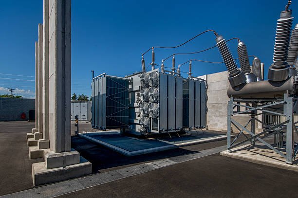
Transformer impedance has a major influence on voltage regulation and load sharing in electrical power systems. In practical transformer operation, impedance determines how much voltage drops under load conditions and how electrical current is distributed when multiple transformers operate in parallel. Because modern power systems rely heavily on stable voltage supply, balanced transformer loading, and reliable power distribution, transformer impedance becomes one of the most important parameters in transformer design and power system engineering.
Voltage regulation refers to the ability of a transformer to maintain stable output voltage as load current changes. When electrical load increases, current flowing through transformer impedance creates internal voltage drop. If transformer impedance is too high, the voltage drop becomes larger, causing poor voltage regulation and unstable power delivery. Conversely, lower impedance improves voltage stability by reducing voltage drop during load changes.
Load sharing becomes especially important when multiple transformers operate in parallel. Parallel transformers are commonly used in substations, industrial plants, renewable energy facilities, and utility networks to increase system capacity and improve reliability. Under parallel operation, transformer impedance determines how load current is distributed among transformers. Transformers with lower impedance naturally carry more current, while transformers with higher impedance carry less. If impedance values are not properly matched, one transformer may become overloaded while others remain underutilized.
Transformer impedance influences voltage regulation by controlling voltage drop under load conditions, and it affects load sharing by determining how current is distributed between transformers operating in parallel. Lower impedance improves voltage regulation but attracts more load current, while higher impedance increases voltage drop and reduces load current sharing.
Proper impedance selection is therefore essential for efficient transformer operation, balanced load distribution, stable voltage supply, and long-term system reliability.
Transformer impedance only affects short-circuit current and has no major influence on voltage regulation or load sharing.False
Transformer impedance directly affects voltage drop during loading and determines how current is shared between parallel transformers, making it critical for voltage regulation and load balancing.
What Is Transformer Impedance?
Transformer impedance is the total opposition to alternating current flow inside the transformer.
Components of Transformer Impedance
| Component | Function |
|---|---|
| Resistance (R) | Produces heat and power loss |
| Reactance (X) | Limits AC current flow |
Together, resistance and reactance form total transformer impedance.
Transformer Impedance Equation
Z=R+jX
Where:
- (Z) = total impedance
- (R) = resistance
- (X) = reactance
- (j) = imaginary operator
In most power transformers, reactance is much larger than resistance.
What Is Voltage Regulation?
Voltage regulation describes how transformer output voltage changes between no-load and full-load conditions.
Voltage Regulation Definition
When transformer load current increases, internal impedance causes voltage drop.
Voltage Regulation Formula
VR%=\frac{V{NL}-V{FL}}{V_{FL}}\times100
Where:
- (VR%) = voltage regulation
- (V_{NL}) = no-load voltage
- (V_{FL}) = full-load voltage
Smaller voltage regulation values indicate better voltage stability.
Why Voltage Drop Occurs
Voltage drop occurs because current flowing through transformer impedance creates internal losses.
Voltage Drop Equation
\Delta V=IZ
Where:
- (\Delta V) = voltage drop
- (I) = load current
- (Z) = transformer impedance
Higher current or higher impedance increases voltage drop.
Influence of Low Impedance on Voltage Regulation
Low-impedance transformers produce smaller voltage drop.
Advantages of Low Impedance
| Advantage | Benefit |
|---|---|
| Better voltage stability | Improved power quality |
| Lower voltage drop | Stable customer voltage |
| Improved load performance | Better equipment operation |
Distribution transformers commonly use relatively low impedance values for this reason.
Influence of High Impedance on Voltage Regulation
High impedance increases voltage drop under load.
Effects of High Impedance
| Effect | Consequence |
|---|---|
| Larger voltage drop | Reduced voltage stability |
| Poorer regulation | Sensitive equipment problems |
| Greater reactive voltage loss | Lower efficiency |
However, higher impedance also improves fault current limitation.
Balancing Voltage Regulation and Protection
Transformer designers must balance competing requirements.
Engineering Trade-Off
| Lower Impedance | Higher Impedance |
|---|---|
| Better voltage regulation | Better fault limitation |
| Higher short-circuit current | Larger voltage drop |
| Improved efficiency | Reduced mechanical stress |
Choosing proper impedance requires careful system analysis.
What Is Load Sharing?
Load sharing refers to how current is distributed between transformers operating in parallel.
Why Parallel Transformers Are Used
| Purpose | Benefit |
|---|---|
| Increase system capacity | Higher load support |
| Improve reliability | Backup operation |
| Maintenance flexibility | Reduced downtime |
Parallel transformer operation is widely used in substations and industrial plants.
How Impedance Affects Load Sharing
Transformer current sharing depends largely on impedance magnitude.
Basic Load Sharing Principle
Transformers with lower impedance carry more current.
Current Sharing Relationship
I\propto\frac{1}{Z}
Where:
- (I) = transformer current
- (Z) = transformer impedance
Lower impedance attracts higher load current.
Example of Unequal Impedance
Parallel Transformer Example
| Transformer | Impedance | Load Current |
|---|---|---|
| Transformer A | 5% | Higher current |
| Transformer B | 8% | Lower current |
Transformer A will carry significantly more load.
Problems Caused by Unequal Impedance
Unequal impedance creates operational imbalance.
Main Load Sharing Problems
| Problem | Consequence |
|---|---|
| Transformer overload | Excessive heating |
| Unequal aging | Reduced lifespan |
| Reduced efficiency | Higher losses |
| Protection mismatch | Relay coordination problems |
One transformer may become overloaded even when total system load appears acceptable.
Why Equal Impedance Is Important
Parallel transformers should have nearly identical impedance values.
Recommended Impedance Matching
| Parameter | Typical Requirement |
|---|---|
| Percent impedance difference | Within ±7.5% |
| Voltage ratio | Nearly identical |
| Phase shift | Same vector group |
These conditions ensure balanced operation.
Load Sharing Formula
Transformer load current depends on impedance ratio.
Parallel Current Sharing Equation
\frac{I_1}{I_2}=\frac{Z_2}{Z_1}
Where:
- (I_1) = current in transformer 1
- (I_2) = current in transformer 2
- (Z_1) = impedance of transformer 1
- (Z_2) = impedance of transformer 2
Current divides inversely proportional to impedance.
Transformer Overloading Risks
Improper load sharing can overload transformers.
Overloading Consequences
| Consequence | Effect |
|---|---|
| Excessive temperature | Insulation aging |
| Hot spot formation | Reduced lifespan |
| Oil degradation | Dielectric failure |
Continuous overload significantly shortens transformer life.
Copper Losses and Load Sharing
Unequal load sharing affects transformer losses.
Copper Loss Equation
P_{cu}=I^2R
Where:
- (P_{cu}) = copper loss
- (I) = current
- (R) = winding resistance
Overloaded transformers experience much higher heating losses.
Reactive Power and Impedance
Transformer reactance also affects reactive power flow.
Reactive Power Equation
Q=VI\sin\phi
Where:
- (Q) = reactive power
- (V) = voltage
- (I) = current
- (\phi) = phase angle
Reactive power influences voltage stability throughout the system.
Impedance and System Stability
Transformer impedance contributes to overall power system stability.
Stability Functions
| Function | Benefit |
|---|---|
| Voltage support | Stable operation |
| Controlled current flow | Balanced loading |
| Reduced disturbances | Improved reliability |
Industrial Applications of Impedance Control
Industrial systems often require careful impedance selection.
Industrial Examples
| Industry | Impedance Purpose |
|---|---|
| Steel plants | Arc furnace stabilization |
| Mining systems | Motor starting support |
| Chemical plants | Process stability |
Renewable Energy Systems
Renewable energy facilities rely heavily on stable voltage regulation.
Renewable Applications
| Application | Importance |
|---|---|
| Solar farms | Grid voltage stability |
| Wind farms | Power flow control |
| Battery storage | Dynamic load balancing |
Railway and Traction Systems
Railway transformers experience highly dynamic loading.
Railway Requirements
| Requirement | Purpose |
|---|---|
| Stable traction voltage | Reliable train operation |
| Balanced load distribution | System reliability |
| Harmonic limitation | Power quality improvement |
Smart Grids and Intelligent Monitoring
Modern power systems increasingly use digital monitoring.
Smart Monitoring Functions
| Technology | Function |
|---|---|
| Real-time impedance monitoring | Load balancing |
| AI diagnostics | Predictive maintenance |
| Smart transformers | Dynamic voltage regulation |
Factors Affecting Transformer Impedance
Several design parameters influence impedance.
Main Design Factors
| Factor | Effect |
|---|---|
| Winding spacing | Leakage reactance |
| Conductor size | Resistance |
| Core geometry | Magnetic coupling |
| Winding arrangement | Current distribution |
International Standards for Parallel Operation
Transformer standards define parallel operation requirements.
Common Standards
| Standard | Organization |
|---|---|
| IEC 60076 | IEC |
| IEEE C57 | IEEE |
These standards ensure safe and reliable transformer operation.
Key Effects of Impedance on Voltage Regulation and Load Sharing
| Impedance Effect | Operational Impact |
|---|---|
| Controls voltage drop | Voltage regulation |
| Determines current distribution | Load sharing |
| Influences transformer heating | Thermal performance |
| Affects system stability | Grid reliability |
| Impacts efficiency | Energy performance |
How Is the Appropriate Impedance Value Selected for Different Applications?
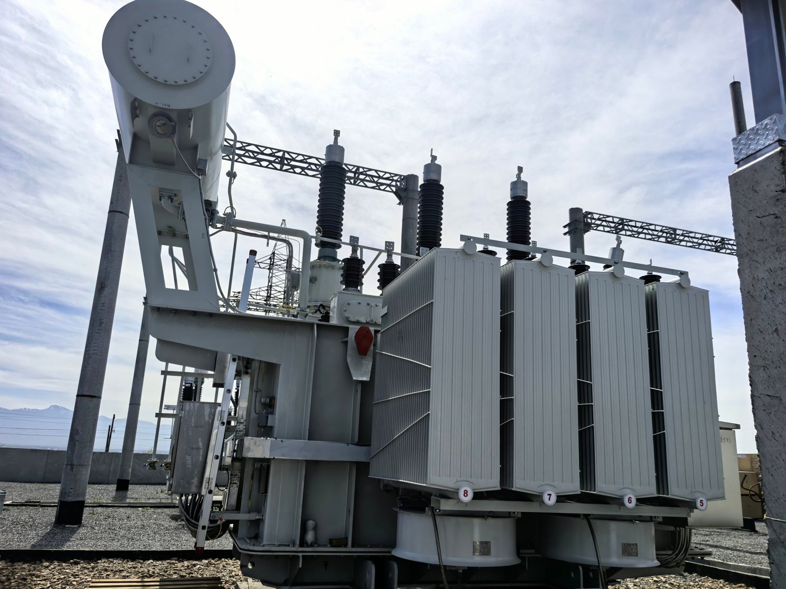
Selecting the appropriate transformer impedance value is one of the most important engineering decisions in transformer design and power system planning. Transformer impedance directly affects short-circuit current limitation, voltage regulation, load sharing, system protection coordination, thermal performance, mechanical stress resistance, and overall electrical network stability. Because different industries and applications operate under different electrical conditions, there is no single ideal impedance value suitable for every transformer application. Instead, engineers must carefully balance multiple operational requirements to determine the optimal impedance range for each specific system.
In practical power systems, low transformer impedance improves voltage regulation and reduces voltage drop under load conditions, but it also allows very high short-circuit current during fault conditions. High transformer impedance limits fault current and reduces mechanical stress, but it increases voltage drop and can negatively affect voltage stability. The selection process therefore requires detailed analysis of fault levels, load characteristics, protection systems, transformer capacity, installation environment, and operational reliability requirements.
Different applications such as utility substations, industrial plants, renewable energy systems, railway electrification networks, data centers, mining facilities, and arc furnace operations all require different impedance characteristics. Distribution transformers generally use lower impedance values to maintain stable customer voltage, while large transmission transformers often use higher impedance values to limit fault current within safe equipment ratings.
The appropriate transformer impedance value is selected by balancing short-circuit current limitation, voltage regulation, load sharing, protection coordination, thermal performance, and application-specific operational requirements to achieve safe, stable, and efficient power system operation.
Proper impedance selection is critical for transformer reliability, electrical safety, equipment protection, and long-term power system performance.
The best transformer impedance value is always the lowest possible impedance because low impedance improves transformer efficiency in every application.False
While lower impedance improves voltage regulation, it also increases short-circuit current and fault stress. Different applications require different impedance values depending on protection, stability, and operational requirements.
Why Transformer Impedance Selection Is Important
Transformer impedance affects multiple electrical and mechanical system characteristics.
Main Factors Influenced by Impedance
| Parameter | System Impact |
|---|---|
| Short-circuit current | Protection coordination |
| Voltage regulation | Power quality |
| Load sharing | Parallel operation |
| Mechanical stress | Transformer durability |
| Thermal performance | Insulation lifespan |
Improper impedance selection can create serious operational problems.
What Is Transformer Impedance?
Transformer impedance is the total opposition to alternating current flow.
Components of Transformer Impedance
| Component | Function |
|---|---|
| Resistance (R) | Produces heating losses |
| Reactance (X) | Limits AC current flow |
Together, resistance and reactance form total transformer impedance.
Transformer Impedance Equation
Z=R+jX
Where:
- (Z) = total impedance
- (R) = resistance
- (X) = reactance
- (j) = imaginary operator
In power transformers, reactance is typically much larger than resistance.
Understanding Percentage Impedance
Transformer impedance is usually expressed as percentage impedance.
Percentage Impedance Formula
Z%=\frac{V{sc}}{V{rated}}\times100
Where:
- (Z%) = percentage impedance
- (V_{sc}) = short-circuit voltage
- (V_{rated}) = rated voltage
This value indicates how much voltage is required to circulate rated current during a short-circuit test.
Main Factors Considered When Selecting Impedance
Several engineering factors determine the appropriate impedance value.
Primary Selection Criteria
| Design Factor | Importance |
|---|---|
| Fault current limitation | System protection |
| Voltage regulation | Stable operation |
| Transformer size | Capacity matching |
| System voltage level | Grid compatibility |
| Load characteristics | Operational stability |
Each factor influences final impedance selection differently.
Short-Circuit Current Limitation
Fault current limitation is one of the most important reasons for selecting transformer impedance.
Short-Circuit Current Formula
I{sc}=\frac{I{rated}}{Z_{pu}}
Where:
- (I_{sc}) = short-circuit current
- (I_{rated}) = rated current
- (Z_{pu}) = per-unit impedance
Lower impedance produces higher short-circuit current.
Why Fault Current Limitation Matters
High short-circuit current can damage electrical equipment.
Problems Caused by Excessive Fault Current
| Problem | Consequence |
|---|---|
| Extreme heating | Equipment damage |
| Electromagnetic stress | Winding deformation |
| Arc flash hazards | Personnel danger |
| Circuit breaker overload | Protection failure |
Higher transformer impedance reduces these risks.
Voltage Regulation Requirements
Voltage regulation is another critical factor.
Voltage Regulation Formula
VR%=\frac{V{NL}-V{FL}}{V_{FL}}\times100
Where:
- (VR%) = voltage regulation
- (V_{NL}) = no-load voltage
- (V_{FL}) = full-load voltage
Lower impedance generally provides better voltage regulation.
Balancing Fault Protection and Voltage Regulation
Transformer design requires compromise between competing objectives.
Engineering Trade-Off
| Lower Impedance | Higher Impedance |
|---|---|
| Better voltage regulation | Better fault limitation |
| Smaller voltage drop | Reduced short-circuit current |
| Higher fault stress | Increased voltage variation |
Optimal impedance depends on application requirements.
Distribution Transformer Impedance Selection
Distribution transformers typically use lower impedance values.
Typical Distribution Transformer Impedance
| Transformer Rating | Typical Impedance |
|---|---|
| Small distribution transformer | 4%–5% |
| Medium distribution transformer | 5%–6% |
Why Distribution Transformers Use Lower Impedance
Distribution systems prioritize stable customer voltage.
Distribution System Priorities
| Priority | Reason |
|---|---|
| Stable voltage | Customer equipment protection |
| Reduced voltage drop | Improved power quality |
| Efficient operation | Lower energy loss |
However, protection equipment must handle higher fault current.
Power Transmission Transformer Impedance Selection
Large transmission transformers usually use higher impedance.
Typical Transmission Transformer Impedance
| Transformer Type | Typical Impedance |
|---|---|
| Transmission transformer | 8%–15% |
| Generator step-up transformer | 10%–18% |
Why Transmission Systems Use Higher Impedance
Transmission networks experience extremely high fault levels.
Transmission System Benefits of Higher Impedance
| Benefit | Purpose |
|---|---|
| Reduced fault current | Protection coordination |
| Lower mechanical stress | Improved durability |
| Better grid stability | Reliable operation |
Industrial Transformer Impedance Selection
Industrial applications often require customized impedance values.
Industrial Impedance Requirements
| Industry | Typical Requirement |
|---|---|
| Steel plants | High impedance |
| Mining facilities | Medium-to-high impedance |
| Chemical plants | Moderate impedance |
Arc Furnace Transformer Applications
Arc furnaces require especially high impedance.
Why Arc Furnaces Need High Impedance
| Reason | Benefit |
|---|---|
| Current stabilization | Stable arc operation |
| Fault current limitation | Equipment protection |
| Reduced electrical disturbance | Grid stability |
Arc furnace transformers may use impedance values above 15%.
Renewable Energy System Requirements
Renewable energy systems require careful impedance coordination.
Renewable Energy Applications
| Application | Impedance Purpose |
|---|---|
| Solar farms | Inverter protection |
| Wind farms | Voltage stabilization |
| Battery storage | Power flow control |
Railway Transformer Impedance Selection
Railway electrification systems experience dynamic loading conditions.
Railway System Requirements
| Requirement | Purpose |
|---|---|
| Fault current control | Railway safety |
| Stable traction voltage | Reliable train operation |
| Harmonic reduction | Power quality improvement |
Parallel Transformer Operation
Parallel transformers require closely matched impedance values.
Importance of Matching Impedance
| Requirement | Reason |
|---|---|
| Similar percentage impedance | Equal load sharing |
| Similar X/R ratio | Stable operation |
| Matching voltage ratio | Circulating current prevention |
Load Sharing Relationship
Current sharing depends on transformer impedance.
Parallel Current Sharing Equation
\frac{I_1}{I_2}=\frac{Z_2}{Z_1}
Where:
- (I_1) = transformer 1 current
- (I_2) = transformer 2 current
- (Z_1) = transformer 1 impedance
- (Z_2) = transformer 2 impedance
Unequal impedance causes unequal loading.
Mechanical Stress and Impedance Selection
Fault current creates strong electromagnetic forces.
Electromagnetic Force Equation
F\propto I^2
Where:
- (F) = electromagnetic force
- (I) = fault current
Higher impedance reduces mechanical fault stress.
Thermal Performance Considerations
Transformer impedance influences thermal behavior.
Copper Loss Equation
P_{cu}=I^2R
Where:
- (P_{cu}) = copper loss
- (I) = current
- (R) = winding resistance
Improper loading caused by impedance mismatch increases heating.
System Voltage Level Considerations
Higher-voltage systems usually require higher impedance.
Typical Voltage-Level Trends
| Voltage Level | Typical Impedance Trend |
|---|---|
| Low-voltage distribution | Lower impedance |
| High-voltage transmission | Higher impedance |
Economic Considerations
Transformer impedance also affects project economics.
Economic Factors
| Factor | Financial Impact |
|---|---|
| Larger conductors | Lower impedance cost increase |
| Higher fault-rated equipment | Protection cost increase |
| Voltage regulation equipment | Additional infrastructure cost |
International Standards and Impedance
Transformer impedance must comply with international standards.
Common Standards
| Standard | Organization |
|---|---|
| IEC 60076 | IEC |
| IEEE C57 | IEEE |
These standards define impedance tolerances and testing requirements.
Smart Grids and Modern Impedance Optimization
Modern smart grids increasingly use advanced system modeling.
Smart Grid Technologies
| Technology | Benefit |
|---|---|
| Digital simulation | Accurate impedance optimization |
| AI-based analysis | Predictive fault studies |
| Smart transformers | Dynamic system adaptation |
Typical Impedance Ranges by Application
| Application | Typical Impedance |
|---|---|
| Distribution transformer | 4%–6% |
| Power transformer | 6%–15% |
| Generator transformer | 8%–18% |
| Furnace transformer | 10%–20% |
| Railway transformer | 8%–15% |
Key Principles for Selecting Transformer Impedance
| Selection Principle | Purpose |
|---|---|
| Limit fault current | Protection |
| Maintain voltage stability | Power quality |
| Ensure balanced load sharing | Reliability |
| Reduce mechanical stress | Durability |
| Match system requirements | Operational stability |
Conclusion
Transformer impedance represents the internal opposition to AC current flow caused by resistance and leakage reactance within the transformer. It plays a critical role in limiting fault currents, controlling voltage drop, and enabling proper load sharing between parallel transformers. Selecting the correct impedance value is essential for balancing system protection, efficiency, and operational stability in modern power networks.
FAQ
Q1: What does impedance mean in a transformer?
Transformer impedance is the opposition a transformer presents to alternating current (AC). It consists of:
Resistance: Caused by winding conductors
Reactance: Caused by magnetic flux and leakage fields
Impedance affects voltage regulation, fault current levels, and the overall performance of the transformer.
Q2: How is transformer impedance expressed?
Transformer impedance is usually expressed as a percentage impedance (%Z).
It represents the percentage of rated voltage required to circulate full-load current when the secondary winding is short-circuited.
For example:
A transformer with 6% impedance requires 6% of rated voltage to produce full-load current under short-circuit conditions.
Q3: Why is transformer impedance important?
Transformer impedance is important because it influences:
Short-circuit current limitation
Voltage regulation under load
Load sharing between parallel transformers
System protection coordination
Proper impedance selection is critical for safe and stable power system operation.
Q4: How does impedance affect fault current?
Higher transformer impedance limits short-circuit current, while lower impedance allows larger fault currents.
High impedance: Better fault current limitation but larger voltage drop
Low impedance: Better voltage regulation but higher fault current risk
Engineers choose impedance values based on system protection and operational requirements.
Q5: How does impedance impact voltage regulation?
Voltage regulation refers to the change in output voltage from no-load to full-load conditions.
Higher impedance causes greater voltage drop under load
Lower impedance improves voltage stability
Proper impedance balancing helps maintain stable voltage delivery to connected equipment.
Q6: What factors determine transformer impedance?
Transformer impedance depends on:
Winding design and spacing
Core geometry
Leakage flux path
Conductor material and size
Transformer power rating
Manufacturers carefully design impedance to meet application-specific requirements.
Q7: Why must impedance match when transformers operate in parallel?
When transformers operate in parallel, similar impedance values are necessary to ensure:
Balanced load sharing
Stable voltage performance
Prevention of circulating currents
Proper system reliability
Large impedance mismatches can overload one transformer while underutilizing another.
Q8: Can transformer impedance be adjusted?
Transformer impedance is primarily determined during manufacturing and cannot be easily changed afterward.
However, system engineers can manage impedance effects through:
Proper transformer selection
Tap changer adjustments
Reactor installation in some applications
Correct design planning is essential for optimal performance.
References
IEC 60076 – Power Transformers
https://webstore.iec.ch/publication/602
IEEE C57 Series – Transformer Standards
https://standards.ieee.org
Electrical Engineering Portal – Transformer Impedance Explained
https://electrical-engineering-portal.com
CIGRE – Transformer Electrical Characteristics Studies
https://www.cigre.org
NEMA – Transformer Design Standards
https://www.nema.org
IEEE Power & Energy Society – Transformer Engineering Research
https://ieeexplore.ieee.org