Transformers play a vital role in transmitting and distributing electrical energy efficiently. However, like all electrical equipment, they are not 100% efficient and experience energy losses. These losses are mainly categorized as iron (core) losses and copper (winding) losses, both of which reduce a transformer's overall efficiency and contribute to operational costs. Understanding these losses and their implications is essential for improving transformer design, selection, and usage.
What Are Iron (Core) Losses in Transformers?
Understanding transformer losses is essential for improving energy efficiency, reducing operational costs, and ensuring accurate performance benchmarking. Among these losses, iron losses (also called core losses) occur continuously whenever the transformer is energized, regardless of the load on its windings. These losses represent non-recoverable energy consumption caused by the magnetic behavior of the transformer's steel core.
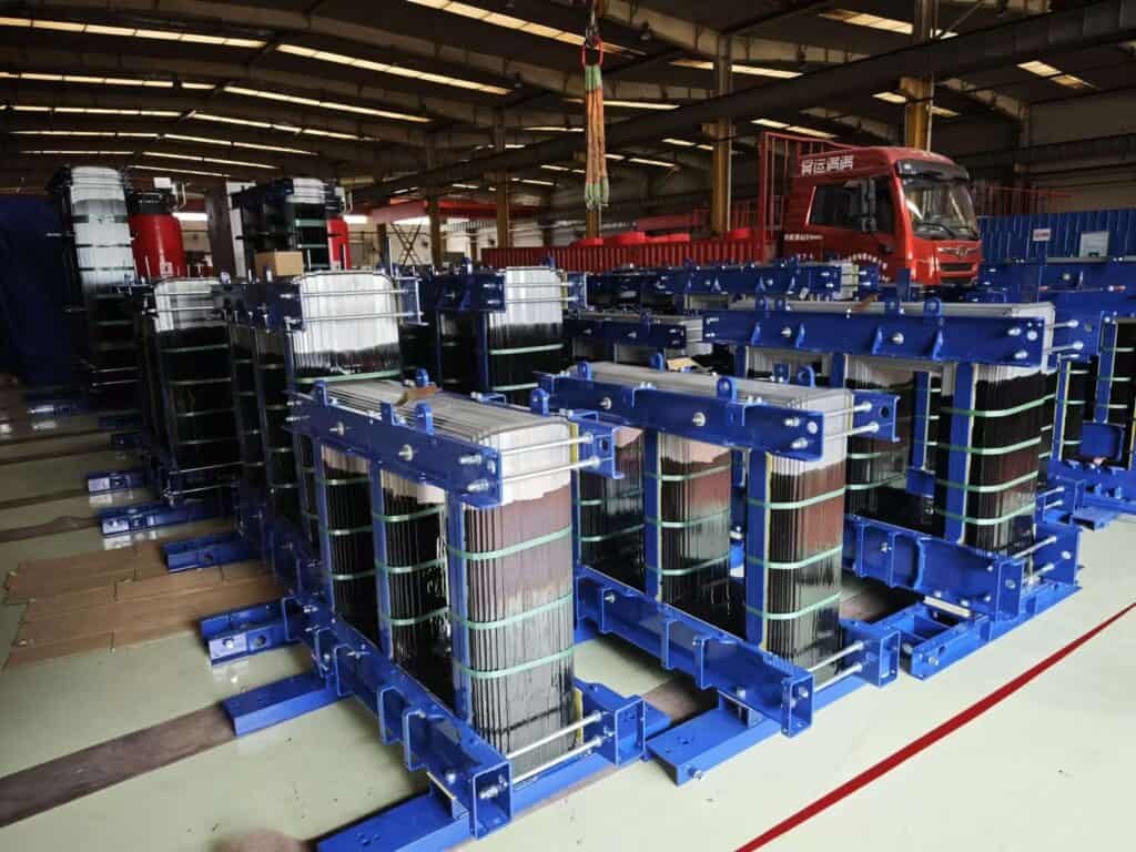
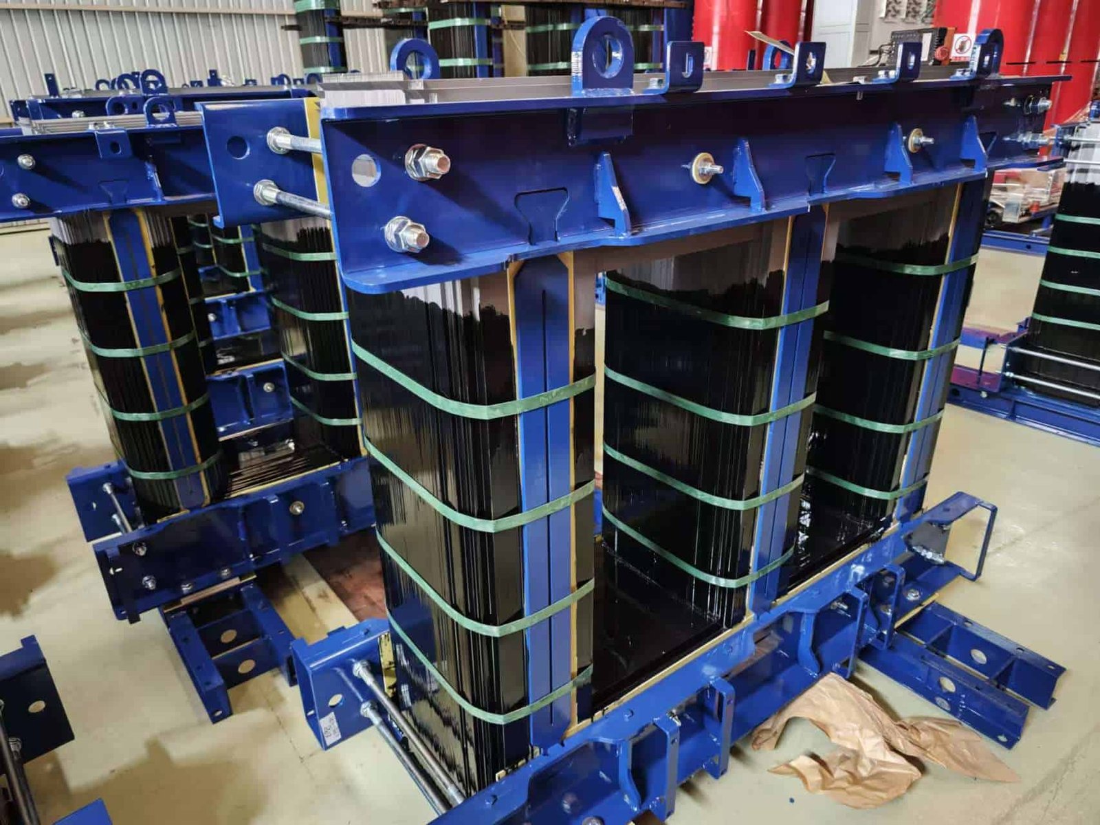
Iron (or core) losses in transformers are the energy losses that occur in the magnetic core due to alternating magnetic flux, even when the transformer is unloaded. These losses consist of hysteresis losses—caused by the reversal of magnetism in the core material—and eddy current losses—caused by induced currents within the steel laminations. Iron losses are proportional to voltage and frequency and are independent of load.
They are measured during the no-load test and contribute to constant operating energy consumption.
Iron losses in a transformer vary with the load current.False
Iron losses depend on voltage and frequency, not on load current. They occur even under no-load conditions.
Components of Iron Losses
| Type of Loss | Description |
|---|---|
| Hysteresis Loss (Ph) | Caused by the lag of magnetic domains aligning with alternating flux. Depends on core material and frequency. |
| Eddy Current Loss (Pe) | Circulating currents induced in the core laminations generate heat. Proportional to the square of voltage and inversely to lamination thickness. |
Total Iron Loss $P{iron} = P{hysteresis} + P_{eddy}$
Mathematical Formulation
| Loss Type | Formula | Influence Factors |
|---|---|---|
| Hysteresis Loss | $P_h = Kh \cdot f \cdot B{max}^n \cdot V$ | Frequency $f$, flux density $B$, volume $V$ |
| Eddy Current Loss | $P_e = Ke \cdot f^2 \cdot B{max}^2 \cdot t^2 \cdot V$ | Lamination thickness $t$, frequency, voltage |
Typical Iron Loss Values
| Transformer Rating | Voltage (kV) | No-Load Loss (W) | Iron Loss % of Full Load |
|---|---|---|---|
| 100 kVA | 11/0.4 | ~300–500 W | 1.5–2% |
| 500 kVA | 11/0.4 | ~800–1200 W | 1.2–1.5% |
| 2.5 MVA | 33/11 | ~2500–3500 W | 0.8–1.2% |
| 40 MVA | 132/33 | ~15,000–18,000 W | 0.3–0.6% |
How to Reduce Iron Losses
| Method | Effectiveness |
|---|---|
| Use of CRGO Steel | Grain-oriented steel aligns magnetic domains, reduces hysteresis |
| Thin Laminations | Reduces eddy currents by increasing resistance |
| Use of Amorphous Core | 60–70% lower core loss than CRGO steel |
| Proper Annealing | Reduces internal stresses and improves magnetic properties |
| Optimal Core Design | Minimizes flux leakage and ensures uniform flux density |
Real-World Case – Low-Loss 11/0.4 kV Distribution Transformer
- Rating: 250 kVA, ONAN cooled
- Core: CRGO laminated core, 0.23 mm thick
- Iron Loss: 550 W at rated voltage
- Load Loss: 2400 W at full load
- Efficiency at full load: 98.3%
Result: Reduced annual energy loss, saving ~$300/year in standby power compared to conventional models—achieved through optimized core material and geometry.
Measurement and Testing of Iron Losses
| Test | Procedure |
|---|---|
| Open-Circuit Test | Apply rated voltage to HV side, measure input power at no load |
| Wattmeter Reading | Directly shows core loss under constant excitation |
| Loss Correction | Adjusted for temperature and waveform accuracy as per IEC 60076 |
Regulatory Standards on Core Loss Limits
| Standard | Core Loss Provision |
|---|---|
| IEC 60076-1 | Specifies no-load loss limits by rating and voltage class |
| IS 1180 Part 1 | Indian standard for energy-efficient transformers |
| DOE 10 CFR Part 431 | US energy performance limits for distribution transformers |
What Are Copper Losses in Transformers?
When a transformer delivers power to a load, current flows through its primary and secondary windings, both of which have inherent electrical resistance. This resistance leads to power dissipation in the form of heat—a loss referred to as copper loss or I²R loss. These losses increase with the load and directly affect transformer efficiency, thermal performance, and operating cost.
Copper losses in transformers refer to the resistive (I²R) losses in the primary and secondary windings due to the flow of current. These losses are proportional to the square of the load current and vary with the transformer's loading level. Copper losses increase the operating temperature, reduce efficiency under high load, and are the dominant loss component during full-load conditions.
Copper losses are dynamic and peak at full load, making them crucial in transformer efficiency calculations and thermal design.
Copper losses remain constant regardless of the load.False
Copper losses vary with the square of the load current. They are zero at no-load and maximum at full-load.
Components of Copper Losses
| Type of Copper Loss | Description |
|---|---|
| Primary Winding Loss | Loss due to current in the high-voltage winding |
| Secondary Winding Loss | Loss due to current in the low-voltage winding |
| Stray Load Losses | Additional loss from leakage flux heating structural parts |
Total Copper Loss $P_{Cu} = I_1^2 R_1 + I_2^2 R2 + P{stray}$
How Copper Losses Behave
| Parameter | Relationship |
|---|---|
| Proportional To | $text{(Load Current)}^2$ |
| Zero At | No-load (since current is near zero) |
| Maximum At | Full-load or overload conditions |
| Impact On Efficiency | Reduces efficiency during peak loading |
Typical Copper Loss Values
| Transformer Rating | Voltage (kV) | Full Load Current | Load Loss (W) |
|---|---|---|---|
| 100 kVA | 11/0.4 | ~5.25 A (HV) | 1500–1800 W |
| 500 kVA | 11/0.4 | ~26 A | 4300–5200 W |
| 2.5 MVA | 33/11 | ~44 A (HV) | 14,000–16,500 W |
| 40 MVA | 132/33 | ~175 A (HV) | 90,000–120,000 W |
How to Reduce Copper Losses
| Method | Impact |
|---|---|
| Use of Larger Conductors | Reduces resistance, lowers losses |
| Compact Winding Design | Shortens mean turn length and improves cooling |
| High-Conductivity Copper | Improves current flow with lower resistive loss |
| Lower Operating Temperature | Reduces resistance (resistance increases with heat) |
| Optimized Flux Path | Reduces leakage flux and stray losses |
Real-World Example – 1000 kVA Distribution Transformer
- Voltage: 11/0.433 kV
- Copper: 99.99% ETP grade
- Load Loss at 75 °C: 6.5 kW
- Full-load efficiency: 98.45%
- Stray loss: 3% of total copper loss
Result: High energy performance under full load and minimal thermal rise, thanks to low-resistance winding design and enhanced core clamping.
Measurement and Testing of Copper Losses
| Test | Procedure |
|---|---|
| Short-Circuit Test | Apply low voltage to HV winding, short LV side, measure power loss |
| Wattmeter Reading | Represents total copper loss under test current |
| Resistance Correction | Adjust values to 75 °C (standard temp) using $R_{75} = R_t [1 + 0.004(T - 75)]$ |
Regulatory and Efficiency Standards
| Standard | Requirement |
|---|---|
| IEC 60076-1 | Specifies maximum allowable load losses for each rating |
| IS 1180 | Defines energy efficiency star ratings in India |
| DOE 2016 (US) | Load loss limits for distribution transformers |
How Do Iron and Copper Losses Affect Transformer Efficiency?
Transformer efficiency is the ratio of useful power output to total power input, and it’s primarily governed by iron losses (constant) and copper losses (variable with load). These two losses together determine how effectively a transformer converts electrical power with minimal energy waste. Understanding their interaction is key to designing, selecting, and operating energy-efficient transformers in any setting.
Transformer efficiency is reduced by the combined effect of iron (core) and copper (winding) losses. Iron losses occur constantly when the transformer is energized, while copper losses increase with load. The efficiency is low at light loads (due to fixed iron losses) and drops at high loads (due to rising copper losses). Maximum efficiency occurs at a specific load where iron and copper losses are equal.
Optimizing this balance is crucial for transformers operating under varying load profiles.
Transformer efficiency increases indefinitely as the load increases.False
Transformer efficiency peaks when copper and iron losses are equal. Beyond that point, rising copper losses cause efficiency to decrease.
Transformer Efficiency Formula
$$\eta = \frac{\text{Output Power}}{\text{Output Power + Iron Loss + Copper Loss}}$$
Where:
- Iron Loss (P₀) = constant (no-load)
- Copper Loss (Pcu) = varies with square of load current
$$\eta_{%} = \frac{V \cdot I \cdot \cos \phi}{V \cdot I \cdot \cos \phi + P_0 + I^2 R}$$
Loss vs. Load Relationship
| Load Level (% of Rated) | Iron Loss (W) | Copper Loss (W) | Efficiency Trend |
|---|---|---|---|
| 0% (No Load) | Constant | 0 | Efficiency = 0% |
| 25% | Constant | 6.25% of full-load copper loss | Low – Iron loss dominates |
| 50% | Constant | 25% | Improving |
| 70–80% | Constant | ~50–64% | Maximum efficiency zone |
| 100% (Full Load) | Constant | 100% | Slightly reduced |
| >100% (Overload) | Constant | >100% | Drops significantly |
Visual: Transformer Efficiency vs Load
| Load (%) | Efficiency (%) – Typical 100 kVA Transformer |
|---|---|
| 0 | 0.0 |
| 25 | ~96.5 |
| 50 | ~98.1 |
| 75 | ~98.6 |
| 100 | ~98.3 |
| 125 | ~97.5 |
Peak efficiency usually occurs between 60% and 80% of rated load.
Key Influences on Efficiency
| Factor | Impact on Losses and Efficiency |
|---|---|
| Iron Core Design | Low-loss CRGO or amorphous materials reduce constant loss |
| Winding Resistance | Thicker conductors lower copper loss at full load |
| Cooling System | Maintains winding temperature, prevents rise in resistance |
| Load Profile | Affects how often the transformer operates near peak load |
| Voltage Regulation | Helps maintain consistent flux density and loss level |
Real-World Case – High-Efficiency 500 kVA Transformer
- Iron Loss: 850 W
- Full-Load Copper Loss: 4300 W
- Operating Load Profile: 60–80% daily average
- Peak Efficiency: 98.65% at 70% load
Optimized for partial load operation, saving approx. 2000 kWh annually vs. standard-efficiency model—enabled by selecting a transformer where losses balance at typical load.
Design Strategy: Matching Load Profile to Efficiency Curve
| Load Profile Type | Suggested Design Focus |
|---|---|
| Constant Light Load | Minimize iron loss (amorphous core ideal) |
| Variable Load (Peak + Idle) | Balance both loss types carefully |
| Heavy Load/Continuous Full Load | Reduce copper loss (larger windings, better cooling) |
Efficiency Standards & Regulations
| Standard | Efficiency Provisions |
|---|---|
| IEC 60076-1 | Defines loss and efficiency testing procedures |
| IS 1180 Part 1 | Star labeling system for distribution transformer efficiency |
| DOE 2016 (US) | Minimum efficiency thresholds by kVA class |
| EU EcoDesign Tier 2 | Enforces low-loss transformer designs in Europe |
What Factors Influence the Magnitude of Iron and Copper Losses in Transformers?
Understanding what determines transformer losses is critical to optimizing performance, improving efficiency, and reducing energy waste. The magnitude of iron (core) and copper (winding) losses depends on multiple physical, electrical, thermal, and design variables. These variables affect how much energy is consumed internally—either through constant magnetic losses or load-related resistive heating.
Iron losses are primarily influenced by core material, frequency, voltage (flux density), and core geometry, while copper losses depend on conductor size, material resistivity, current magnitude, temperature, and winding configuration. Both types of losses are fundamental to transformer efficiency and operational cost.
Optimizing these factors during design ensures longer life, lower power consumption, and better thermal stability.
Transformer losses are fixed and cannot be influenced by design or materials.False
Transformer losses can be significantly reduced through better materials, geometry, thermal management, and design optimization.
Factors Affecting Iron Losses
| Factor | Impact on Iron Loss (Core Loss) |
|---|---|
| Core Material | CRGO steel reduces hysteresis; amorphous metal cuts losses by ~70% |
| Flux Density (B) | Higher flux increases both hysteresis and eddy losses |
| Frequency (f) | Directly increases both hysteresis (linear) and eddy loss (squared) |
| Lamination Thickness (t) | Thinner laminations reduce eddy current loop area |
| Core Geometry | Optimized flux path lowers leakage and improves magnetic efficiency |
| Core Annealing | Stress relief improves magnetic domain alignment, reducing hysteresis |
Factors Affecting Copper Losses
| Factor | Impact on Copper Loss (I²R Loss) |
|---|---|
| Conductor Cross Section | Larger size lowers resistance, reducing losses |
| Winding Configuration | Compact coils reduce mean turn length, minimizing resistance |
| Load Current (I) | Losses increase with square of load current |
| Conductor Material | Copper has lower resistivity than aluminum |
| Operating Temperature | Resistance increases ~0.4% per °C, raising I²R losses |
| Cooling System | Better cooling keeps resistance low by limiting temperature rise |
Interaction of Design and Operating Conditions
| Variable | Affects Iron Loss? | Affects Copper Loss? | Notes |
|---|---|---|---|
| Core Material | ✔ Yes | ✖ No | Hysteresis and eddy losses |
| Conductor Size | ✖ No | ✔ Yes | Larger cross-section = lower resistance |
| Frequency | ✔ Yes | ✖ No (indirectly) | Higher f = higher core loss |
| Voltage | ✔ Yes | ✖ No | Affects flux density |
| Load Level | ✖ No | ✔ Yes | Copper loss increases as load rises |
| Cooling Design | ✖ No (indirect) | ✔ Yes (thermal resistivity) | Affects conductor resistance |
Real-World Optimization Example – 2.5 MVA Transformer
- Core: 0.23 mm CRGO, precision annealed
- Windings: Multi-strand ETP copper, low mean turn length
- Design: Flux density optimized to 1.5 T at 50 Hz
Result:
- Iron loss: 1850 W
- Load loss at full load: 12.5 kW
- Efficiency @ 75% load: 98.65%
By selecting optimized material and geometry, losses were reduced by 12% vs conventional design.
Graphical Summary – Impact of Key Factors
| Parameter Changed | Effect on Losses |
|---|---|
| ↑ Flux Density (B) | ↑ Iron loss sharply |
| ↑ Frequency (Hz) | ↑ Iron loss (linear and squared) |
| ↑ Load Current (I) | ↑ Copper loss (quadratic) |
| ↑ Conductor Area (A) | ↓ Copper loss |
| ↓ Lamination Thickness | ↓ Eddy current loss |
| ↑ Core Quality (Amorphous) | ↓ Total iron loss |
Loss Sensitivity by Rating
| Transformer Rating | Loss Sensitivity |
|---|---|
| ≤250 kVA | Iron loss dominates at low load |
| 250–2000 kVA | Balanced sensitivity to iron and copper losses |
| >2000 kVA | Copper loss is major factor under full-load |
Standards and Material Guidelines
| Standard | Relevance |
|---|---|
| IEC 60076-1 | Loss measurement and temperature correction |
| IS 1180 | Defines permissible loss values by rating |
| DOE Efficiency Rules | Mandates max allowable no-load and full-load losses |
| CRGO Grade M4/M5 | Specified for low-loss core designs |
| Amorphous Core Spec. | Advanced low-core-loss alternative |
How Can Transformer Losses Be Measured and Quantified?
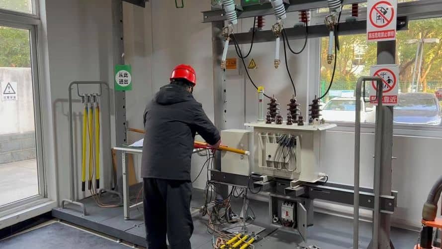
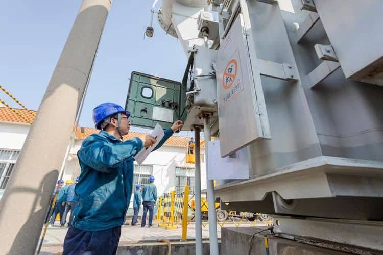
Transformer loss measurement is a critical part of design verification, quality control, and energy efficiency certification. Losses must be accurately quantified using standard electrical testing procedures, both to validate compliance with efficiency regulations and to confirm that the transformer performs as specified under operating conditions. These tests are typically carried out in no-load and full-load conditions using precise electrical instruments.
Transformer losses are measured through two main tests: the open-circuit (no-load) test, which quantifies iron losses, and the short-circuit (full-load) test, which measures copper losses. These tests are conducted under controlled voltage and current conditions using calibrated wattmeters, ammeters, and voltmeters, with corrections applied for temperature and waveform distortion.
Accurate loss quantification ensures regulatory compliance, reliable operation, and performance benchmarking.
Transformer loss measurements can be skipped if manufacturer data is available.False
Actual testing of losses is mandatory per IEC/IEEE standards to confirm design compliance, ensure quality, and calibrate efficiency ratings.
1. Open-Circuit Test – Measures Iron (Core) Losses
| Parameter | Description |
|---|---|
| Test Setup | Apply rated voltage to HV side, LV side left open (no current flow) |
| Measured With | Wattmeter (P₀), Voltmeter (V), Ammeter (I₀) |
| Represents | Hysteresis and eddy current losses in the magnetic core |
| Constant Value | Independent of load, depends only on voltage and frequency |
Formula:
$$\text{Iron Loss} = P_0 = V \cdot I_0 \cdot \cos \phi$$
2. Short-Circuit Test – Measures Copper (Winding) Losses
| Parameter | Description |
|---|---|
| Test Setup | LV side shorted, apply reduced voltage to HV until full-load current flows |
| Measured With | Wattmeter (Psc), Voltmeter (Vsc), Ammeter (Isc) |
| Represents | Full-load copper losses (I²R) in windings |
| Load-Dependent | Varies with square of current |
Formula:
$$\text{Copper Loss} = P_{cu} = I^2 \cdot R$$
Example – 1000 kVA Transformer Loss Test
| Test Type | Measured Parameters | Result |
|---|---|---|
| No-Load (OC) | V = 11 kV, I = 2.1 A, W = 920 W | Iron Loss = 920 W |
| Full-Load (SC) | V = 560 V, I = 52.4 A, W = 7300 W | Copper Loss = 7300 W |
Additional Loss Components (Optional Tests)
| Loss Type | Measurement Method |
|---|---|
| Stray Load Losses | Measured by subtracting theoretical I²R from full copper loss |
| Dielectric Loss | Observed during insulation power factor (tan delta) test |
| Fan & Pump Losses | Included in auxiliary power tests (for ONAF/OFAF/OFAWF) |
Temperature Correction of Measured Losses
| Loss Type | Correction Requirement |
|---|---|
| Copper Losses | Adjust to 75 °C using temperature coefficient (0.004/°C) |
| Iron Losses | Typically stable, minor variation with temp |
Corrected Resistance:
$$R_{75} = R_t \cdot [1 + 0.004 \cdot (T - 75)]$$
Standards and Instruments for Loss Testing
| Standard | Scope |
|---|---|
| IEC 60076-1 & 60076-8 | Defines test setups, accuracy levels, correction methods |
| IS 2026-1 | Indian standard for loss testing and tolerance |
| IEEE Std C57.12.90 | US testing procedures for transformers |
| Instrument | Purpose | Accuracy Class |
|---|---|---|
| Digital Wattmeter | Power measurement | 0.2 or better |
| Digital Ammeter | Current measurement | 0.5 |
| True RMS Voltmeter | Voltage reading | 0.5 |
| Core Loss Analyzer | Optional – for waveform and phase corrections | High |
Real-World Factory Acceptance Testing (FAT) Summary
- Transformer: 2500 kVA, 33/0.4 kV
- Iron Loss (No-Load): 1850 W @ 50 Hz
- Copper Loss (Full-Load): 14,500 W @ 75 °C corrected
- Efficiency @ 100% Load: 98.62%
- All measurements within ±2% of design tolerance
Test results validated for export compliance under IEC and ISO 9001-certified lab conditions
What Design and Operational Measures Can Improve Transformer Efficiency?
In power systems, transformer efficiency is not just a design goal—it's a continuous operational concern. With rising energy costs and strict regulatory standards, both manufacturers and operators must implement proven methods to reduce losses and improve efficiency. This involves materials, geometry, cooling, operation, and maintenance all working together to minimize energy wastage.
Transformer efficiency can be improved by using high-grade core and conductor materials, optimizing magnetic and thermal design, reducing stray losses, implementing intelligent load management, maintaining optimal cooling, and conducting regular preventive maintenance. These measures reduce both iron and copper losses and ensure long-term operational performance.
Adopting these improvements can significantly cut lifecycle energy costs and ensure compliance with energy efficiency regulations.
Transformer efficiency is fixed at manufacturing and cannot be improved afterward.False
While initial efficiency depends on design, operational measures like cooling, load management, and maintenance can significantly influence actual performance over the transformer's life.
Design Measures to Improve Transformer Efficiency
| Design Strategy | Efficiency Benefit |
|---|---|
| Use of Amorphous Metal Core | Reduces core loss by up to 70% vs. CRGO steel |
| High-Grade CRGO (M3/M4) | Low hysteresis and eddy losses at rated frequency |
| Wider, Shorter Windings | Reduces resistance and copper losses (shorter mean turn length) |
| Use of Pure Copper (≥99.9%) | Minimizes resistivity and improves thermal conductivity |
| Thermal Optimized Cooling | Prevents resistive rise from heat buildup |
| Interleaved LV-HV Windings | Reduces leakage inductance and stray losses |
| Optimized Flux Density | Balances iron vs. copper losses for rated load condition |
| Rounded Core Joints | Minimizes magnetic reluctance, reducing local core losses |
Operational Measures to Maximize In-Service Efficiency
| Operation-Based Practice | Loss Reduction Impact |
|---|---|
| Load Balancing Across Phases | Prevents overloading on one phase, reducing copper losses |
| Avoiding Undersized Loads | Ensures transformer operates near peak efficiency load range |
| Scheduled Oil and Filter Maintenance | Maintains dielectric and cooling performance |
| Fan and Radiator Maintenance | Prevents excessive winding temperature rise (higher resistance) |
| De-energizing During Idle Time | Avoids constant iron loss in unutilized units |
| Voltage Optimization | Reduces core saturation and stray loss |
| SCADA Monitoring Integration | Enables real-time loss tracking and alarm-based maintenance |
Efficiency Improvement by Design Class
| Design Improvement | Iron Loss Reduction | Copper Loss Reduction | Total Efficiency Gain |
|---|---|---|---|
| Amorphous Core | High (up to 70%) | None | 0.3–1.5% |
| Copper vs. Aluminum | None | ~15–20% | 0.2–0.8% |
| ONAF Cooling System Upgrade | Indirect | Medium (via temperature) | 0.1–0.5% |
| Optimized Winding Layout | Low | High | 0.5–1.2% |
Real-World Upgrade Case – 1600 kVA Industrial Transformer
- Original: CRGO core, aluminum windings, ONAN cooling
- Retrofit: M4-grade CRGO, pure copper, dual ONAF fans
- Efficiency @ full load: increased from 97.8% to 98.5%
- Energy savings: \~5400 kWh/year
- Payback: <2.5 years via reduced electricity bill
Result: Reliable long-term efficiency improvement with zero operational interruption.
Additional Efficiency Improvement Tactics
| Tactic | Method |
|---|---|
| Smart Tap Changer Settings | Adjust voltage under load to minimize overfluxing |
| Use of Low-Loss Magnetic Clamps | Reduces stray flux-related core losses |
| Digital Temperature Control | Activates cooling only when needed |
| Efficiency-Based Transformer Sizing | Select optimal rating for actual load profile |
| Use of Tier 2/EU EcoDesign Models | Guarantees compliance with the latest standards |
Testing and Certification
| Standard | Efficiency Verification Scope |
|---|---|
| IEC 60076-1 | Loss and efficiency measurements (type tests) |
| IS 1180 (India) | Star label assignment and max allowable losses |
| DOE 10 CFR 431 (USA) | Mandatory performance thresholds for distribution transformers |
| EcoDesign Tier 2 (EU) | Performance labeling for transformers >1 kVA |
Conclusion
Transformer losses—core losses and copper losses—are key factors that directly impact energy efficiency and long-term operational costs. While core losses are constant and occur even at no load, copper losses increase with load. To enhance efficiency, it is essential to select or design transformers with optimized materials, precise manufacturing, and proper loading. Reducing these losses not only saves energy but also aligns with environmental and sustainability goals in modern power systems.
FAQ
Q1: What are the two main types of transformer losses?
A1: The two primary transformer losses are:
Core (Iron) Losses:
Occur in the magnetic core when energized, even with no load
Caused by hysteresis and eddy currents in the core steel
Are constant and related to voltage and frequency
Copper (Load) Losses:
Occur in the transformer windings when load current flows
Caused by resistance (I²R) in conductors
Vary with square of the load current
Q2: How do these losses affect transformer energy efficiency?
A2: Efficiency drops as these losses convert electrical energy into heat
At light loads, core losses dominate
At full or heavy loads, copper losses become significant
High-efficiency transformers are designed to optimize both loss types, ensuring low energy waste across varying load conditions.
Q3: What is the typical efficiency of power transformers?
A3: Modern power transformers achieve efficiency between 98.5% to 99.75%
Distribution transformers may have slightly lower efficiency (95–98.5%)
Lower losses = lower operational cost and reduced carbon footprint over the transformer's life
Q4: How can core and copper losses be reduced?
A4: Loss reduction techniques include:
To reduce core loss:
Use CRGO (Cold Rolled Grain Oriented) or amorphous steel cores
Minimize core flux density
Use thinner laminations to reduce eddy currents
To reduce copper loss:
Use larger conductor cross-section
Optimize winding design and layout
Improve cooling to maintain low resistance under load
Q5: Why are loss reductions important for utilities and industries?
A5: Lower losses result in reduced energy consumption and cost
Support green energy goals and regulatory efficiency compliance (EU EcoDesign, DOE)
Reduce cooling requirements, extending insulation and transformer life
Improve grid performance and power quality
References
"Transformer Losses Explained" – https://www.electrical4u.com/transformer-losses-core-and-copper
"IEEE: Guide for Loading and Efficiency Evaluation of Transformers" – https://ieeexplore.ieee.org/document/8557080
"EU EcoDesign Transformer Efficiency Standards" – https://ec.europa.eu/eurostat/ecodesign/transformers
"ScienceDirect: Transformer Loss Optimization Studies" – https://www.sciencedirect.com/transformer-efficiency-research