Transformer oil plays a critical role in insulation and cooling for oil-immersed transformers. However, leaks and spills—whether due to aging seals, physical damage, or maintenance errors—pose serious safety, environmental, and operational risks. Proper management of transformer oil leakage is essential for regulatory compliance, equipment reliability, and environmental protection. This guide outlines best practices for detecting, containing, and resolving oil leaks and spills.
What Causes Transformer Oil Leaks and Spills?
Transformer oil is critical for insulation, cooling, and arc suppression. However, when this fluid escapes its enclosure—through leaks or accidental spills—it becomes more than just a maintenance issue. It becomes an environmental hazard, a fire risk, and a reliability threat. From aged gaskets to pressure buildup, understanding the causes of oil leakage is essential for prevention, quick response, and regulatory compliance. For utilities and industries operating power transformers, oil containment is not optional—it’s a compliance obligation and a system reliability cornerstone.
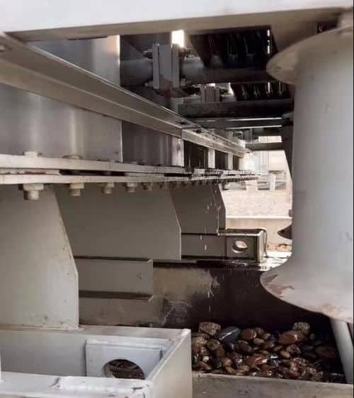
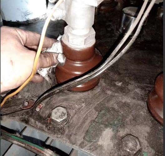
Transformer oil leaks and spills are caused by a combination of mechanical wear, thermal expansion, seal failure, corrosion, pressure imbalances, accidental impacts, and inadequate maintenance practices. The most common leak points include flanges, gaskets, radiators, bushings, drain valves, and weld seams. External factors such as extreme temperature cycles, poor installation, or vibration can worsen the condition. Regular inspections, condition monitoring, and timely seal replacements are key to prevention.
Oil leak prevention is not just about sealing a tank—it’s about controlling risk, cost, and environmental liability. Here’s what you need to know.
Transformer oil leaks are often caused by failed gaskets, corrosion, or thermal cycling.True
Over time, rubber gaskets degrade, weld seams corrode, and repeated heating/cooling causes expansion stress—all contributing to leakage.
All transformer oil leaks are caused by overfilling the tank.False
Overfilling is one possible cause, but the majority of leaks result from mechanical aging, pressure variation, or component failure.
Oil leaks can lead to insulation failure, fire hazards, and environmental contamination.True
Leaking oil reduces dielectric strength, poses fire risks when heated or exposed, and contaminates soil and water, triggering regulatory violations.
Common Causes of Transformer Oil Leaks and Spills
1. Aged or Failed Gaskets and Seals
| Location | Typical Failure Mode |
|---|---|
| Radiator flanges | Rubber hardening, compression set |
| Tank cover | Seal dry-out, UV degradation |
| OLTC chamber | Oil leakage due to vibration and arc heat |
| Cable box seals | Heat-cycle fatigue and mechanical wear |
As gaskets age, they lose elasticity, crack, or compress permanently, allowing oil to seep through joints.
Best Practice: Replace gaskets every 10–15 years, or during major maintenance cycles.
2. Thermal Expansion and Contraction
Transformers experience frequent load-induced temperature shifts:
- Hot oil expands, increasing internal pressure
- Cold conditions cause contraction, stressing joints
| Symptom | Impact |
|---|---|
| Bulging of tank walls | Stress on welds and joints |
| Repeated cycling | Gasket fatigue, loosening of bolts |
| Pressure surges | Relief valve weeping or seal breach |
Remedy: Install conservators or pressure relief valves calibrated to site conditions.
3. Corrosion and Metal Fatigue
Environmental exposure causes:
- Rusted radiators
- Pinhole leaks in weld seams
- Flaking paint hiding metal degradation
| Zone | Risk Level |
|---|---|
| Coastal or industrial areas | High (salt/mist corrosion) |
| Urban rooftops | Medium (UV + pollution exposure) |
| Indoor installations | Low, but still prone to condensation corrosion |
Mitigation: Use corrosion-resistant coatings and perform NDT inspections on weld seams during routine servicing.
4. Improper Torque or Flange Alignment
During installation or maintenance:
- Under-torqued bolts = loose joints
- Over-torqued bolts = damaged gasket compression
- Misaligned flanges = uneven seal contact
| Result | Evidence |
|---|---|
| Drip trails along bolt holes | Flange seal distortion |
| Constant seepage after service | Installation error or fastener fatigue |
Solution: Use calibrated torque tools and follow OEM tightening patterns.
5. Vibration and Mechanical Shock
Transformers vibrate under load—especially with:
- OLTC operations
- Nearby machinery or fault currents
- Fault-induced shock events
These can loosen fittings, misalign seals, and fracture soldered or brazed joints.
Add-on Fixes:
- Anti-vibration mounts
- Secure brackets on radiators and pipework
- Flexible connectors for auxiliary pipes
6. Pressure Build-up Due to Breather Malfunction
Conservators use silica gel breathers to manage pressure and moisture.
| Breather Failure | Consequence |
|---|---|
| Blocked airflow | Internal pressure rises |
| Wet silica gel | Oil absorbs moisture, increasing volume |
| Leaky diaphragm | Oil foam or spillage from expansion |
Inspection Tip: Check breathers quarterly and replace silica gel when color changes.
7. Overfilling or Improper Oil Top-Up
If oil is added:
- Without proper temperature compensation
- When transformer is under load
- Above safe maximum levels
…it may overflow during thermal expansion, especially in sealed units without a conservator.
Fix: Always fill with oil at ambient temperature and measure via calibrated sight gauge.
8. Human Error and Maintenance Neglect
| Mistake | Impact |
|---|---|
| Leaving drain valve open | Rapid leak and tank level drop |
| Skipping gasket recheck | Long-term seepage and contamination |
| Ignoring test results | Minor leaks escalate into critical failures |
Human oversight remains a top contributor to avoidable oil spills.
Chart: Typical Leak Locations by Frequency
| Component Area | Leak Frequency (%) |
|---|---|
| Radiator Flanges | 30% |
| Tank Lid / Top Seal | 20% |
| Bushings | 15% |
| Tap Changer Compartment | 10% |
| Drain Valves & Gauges | 10% |
| Weld Seams | 5% |
| Others (e.g., sensors, couplings) | 10% |
Consequences of Transformer Oil Leaks
| Risk Area | Consequence |
|---|---|
| Electrical | Reduced dielectric strength → insulation failure |
| Thermal | Poor cooling → hotspot formation |
| Environmental | Soil/water contamination → fines, remediation costs |
| Safety | Fire hazard, personnel injury risk |
| Operational | Unplanned downtime and asset de-rating |
In many countries, leaks >1 liter/day require environmental reporting under EPR or EPA rules.
Preventive Measures and Best Practices
| Action | Frequency |
|---|---|
| Infrared inspection of joints and radiators | Bi-annually |
| Gasket replacement and flange re-torquing | Every 10–15 years |
| Breather and conservator check | Quarterly |
| Oil level and sampling test | Annually |
| Sealant or oil-absorbent mats installation | Permanent under all tanks |
Use oil containment bunds with 110–120% volume capacity as per IEC 61936 and NFPA 850.
How Can Leaks Be Detected Early?
Oil leaks in transformers start small—often as seepage, vapor, or slow drips. But left unnoticed, they can evolve into severe mechanical, electrical, environmental, and financial issues. Detecting leaks early is not just a good practice—it’s a critical part of asset protection, fire prevention, and regulatory compliance. Unfortunately, many operators rely solely on visual inspection, which often spots the problem too late. To avoid failure escalation, facilities must adopt early detection tools, structured inspections, and automated monitoring that catch issues before they become crises.
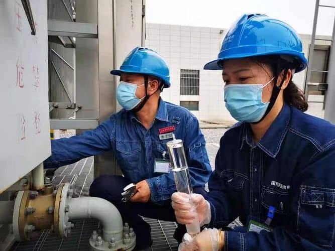
Transformer oil leaks can be detected early using a combination of visual inspections, infrared thermography, ultrasonic sensors, smart oil level gauges, pressure monitoring devices, and continuous environmental sensors. These tools identify minor leaks, pressure anomalies, hot spots, or seal stress long before visible dripping occurs. Early detection helps prevent insulation failure, contamination, fire hazards, and unscheduled downtime. Integration with digital monitoring systems allows alerts to be issued remotely in real time, significantly improving maintenance response.
From gaskets to radiators to tap changers, leak-prone areas need attention—before they fail. Here’s how you can spot them in time.
Infrared thermography and ultrasonic detection can identify early-stage transformer oil leaks before they become visible.True
Thermal and acoustic signatures can reveal oil seepage, stress points, and seal degradation at an early stage.
Daily visual inspections alone are sufficient for early oil leak detection.False
Visual checks may miss minor leaks, vapor escape, or pressure anomalies, especially in concealed or low-access areas.
Smart gauges and oil level sensors help detect slow leaks automatically.True
Digital sensors can monitor oil levels and pressure in real-time, issuing alerts when abnormal drops occur.
Best Methods for Early Detection of Transformer Oil Leaks
1. Infrared (IR) Thermography
Infrared cameras detect temperature variations caused by oil movement, seal friction, or vaporization.
| What It Detects | Why It Works |
|---|---|
| Hotspots on tank seams or radiators | Friction from oil seepage or reduced oil flow |
| Cool zones from evaporative oil loss | Indicates escaping oil along leak path |
| Overheating around bushings or tap changer gaskets | Potential seal degradation under thermal stress |
Use Case: Monthly IR scans during load conditions to detect stress-induced leak precursors.
2. Ultrasonic Acoustic Detection
Ultrasonic sensors detect high-frequency sounds caused by escaping fluids.
| Application | Leak Type |
|---|---|
| Scanning radiators, welds, and gaskets | Pinholes or microfractures |
| Listening near bushings and valves | Minor gas or oil seepage |
| Detecting pressurized seepage under load | Leak before visible drip stage |
Advantage: Can detect leaks under insulation or painted surfaces—non-invasively.
3. Smart Oil Level Monitoring Sensors
Digital float switches or capacitive sensors track oil level trends over time.
| Feature | Benefit |
|---|---|
| Real-time level monitoring | Identifies gradual or sudden oil loss |
| Trend recording | Reveals slow leaks that wouldn’t trigger manual concern |
| Cloud or SCADA alerts | Enables proactive dispatch of maintenance teams |
Use in conservator tanks, OLTC chambers, or sealed units for automated monitoring.
4. Pressure Relief and Internal Pressure Sensors
Leaks often result from pressure imbalance caused by:
- Thermal cycling
- Blocked breathers
- Failing expansion diaphragms
| Detection Point | Indicator |
|---|---|
| Relief valve weeping | Overpressure stress |
| Pressure gauge drop without external trigger | Internal leak or seal failure |
| Conservator bag distortion | Moisture ingress or expansion malfunction |
Install pressure sensors with data logging to catch transient pressure spikes or drops.
5. Environmental Leak Sensors and Spill Detectors
Leak pads, hydrocarbon detectors, and contact moisture sensors detect oil at or below the transformer.
| Sensor Type | Detection Zone |
|---|---|
| Absorbent mat with hydrocarbon strip | Base of transformer or inside bund |
| Optical or capacitive fluid sensors | Drain valves or bushing drip paths |
| IoT-connected pads | Alert when wet or contaminated with oil |
Used in environmentally sensitive areas or unmanned substations.
6. Visual Inspection – Structured, Not Casual
While not the most advanced, routine structured visual inspections are still essential.
| Visual Clue | Leak Suspicion |
|---|---|
| Oily sheen on bolts or flange gaps | Gasket degradation |
| Dark staining or dust-clumped areas | Slow oil weepage |
| Paint bubbling or discoloration | Heat-activated oil seepage |
| Puddles on containment floor | Active leakage in progress |
Visual checks should be backed by checklists and performed weekly or after extreme load cycles.
7. Drone and Robotic Visual Tools
For large or difficult-to-access transformers:
- Drone-mounted cameras can capture IR and visible spectrum images
- Robotic crawlers can inspect underneath pad-mounted units
- AI-based image recognition detects oil trails or thermal anomalies over time
Ideal for remote, hazardous, or restricted-access sites.
Leak Monitoring Table: Detection Tools by Leak Stage
| Leak Stage | Best Detection Method |
|---|---|
| Pre-leak (seal stress, pressure anomaly) | IR thermography, pressure sensors |
| Microleak (no visible drip) | Ultrasonic detection, oil level trend |
| Early leak (surface sheen or vapor loss) | Smart level gauge, IR scan, absorbent sensors |
| Active leak (visible oil or drip) | Visual inspection, pad sensors, DGA (if oil loss affects performance) |
Real-World Early Detection Applications
| Operator | Method Used | Detected Fault | Outcome |
|---|---|---|---|
| European Utility | IR + oil level sensor | Leaking flange on 132kV radiator | Repaired before environmental breach |
| Middle Eastern EPC | Ultrasonic sweep | Weld pinhole on conservator pipe | Rewelded with no downtime |
| Asian Industrial Park | Smart pad + SCADA alert | Gasket drip at bushing base | Prevented 200-liter spill event |
Integration with Digital Monitoring Systems
Many early detection tools can connect to:
- SCADA platforms
- Mobile apps
- Cloud dashboards
- Automated work order systems
Alerts from oil loss trends, pressure drops, or sensor activation can initiate preventive maintenance without human presence.
What Are the Immediate Steps in Case of an Oil Spill?
When a transformer oil spill occurs, it's not just a maintenance issue—it’s a safety emergency, an environmental hazard, and a regulatory event. Whether caused by gasket failure, tank rupture, or overfilling, a spill demands an immediate, coordinated response. Failing to act swiftly can lead to insulation failure, soil and water contamination, legal fines, and fire risks. Every facility operating transformers must have a documented spill response plan, trained personnel, and the correct containment tools. The first 30 minutes determine whether the incident becomes a minor cleanup—or a costly disaster.
The immediate steps in case of a transformer oil spill include: stopping the source of the leak (if safe), evacuating and isolating the area, deploying containment tools (such as absorbent pads or bunds), notifying the environmental safety officer or spill response team, and beginning recovery and cleanup under strict safety protocols. Regulatory bodies must be informed if thresholds are breached. Proper use of personal protective equipment (PPE), spill kits, and reporting procedures are essential to minimize health risks, operational disruption, and environmental damage.
Whether the spill is 5 liters or 500, the protocol remains the same: act fast, act safely, and document everything.
In the event of a transformer oil spill, containment and safety procedures must be initiated immediately.True
Prompt containment and isolation reduce environmental impact, fire risk, and equipment damage.
Transformer oil spills can be ignored if they occur in remote or outdoor locations.False
All spills—regardless of location—pose contamination risks and must be documented, contained, and cleaned per regulation.
Oil spill response requires the use of PPE, absorbents, and immediate area isolation.True
Personnel safety and spill control are top priorities during any oil-related incident.
Step-by-Step Immediate Response to a Transformer Oil Spill
1. Ensure Personnel Safety First
| Action | Reason |
|---|---|
| Wear PPE (oil-resistant gloves, boots, goggles, flame-retardant suit) | Prevent skin contact, inhalation of vapors, or electrocution |
| Isolate power supply (if safe to do so) | Reduce arc flash/fire risk |
| Evacuate non-essential personnel | Limit exposure and allow emergency access |
If the transformer is energized, keep a safe radius of 3–5 meters and contact control room for shutdown authorization.
2. Contain the Spill at the Source
| Method | Tool |
|---|---|
| Plug or clamp leaking valve or pipe | Temporary mechanical plug or containment sock |
| Tighten accessible bolts or gaskets (if safe) | Torque tools and sealing putty |
| Divert oil into containment trays | Oil pans or emergency catch trays |
Note: Never attempt containment near energized parts unless the area is de-energized and confirmed safe by electrical personnel.
3. Deploy Spill Containment Materials
| Containment Type | Examples |
|---|---|
| Absorbents | Hydrophobic pads, socks, booms |
| Barriers | Portable bund walls or oil stop mats |
| Neutralizers (if applicable) | For ester oil or synthetic fluid compatibility |
Surround the leak and guide oil toward a safe recovery zone using gravity or absorbents.
Key Tip: Hydrophobic materials should be used to absorb oil without soaking up water during outdoor incidents.
4. Notify Internal Safety & Environmental Teams
Immediately inform:
- On-duty safety officer
- Environmental compliance lead
- Operations control room
They will initiate the site-specific Spill Response Plan (SRP) and begin coordination with:
- External spill contractors (if needed)
- Regulatory authorities (if reportable spill)
- Utility operations or emergency managers
5. Shut Down Equipment If Warranted
| Condition | Action |
|---|---|
| Active leak into energized enclosure | De-energize transformer if safe |
| Oil level falls below alarm | Trip breaker or cut feeder |
| Risk of fire or dielectric failure | Emergency shutdown procedure |
Always coordinate with system control and follow isolation/lockout protocols.
6. Begin Oil Recovery and Cleanup
| Task | Tool |
|---|---|
| Absorb residual oil on surfaces | Oil-only absorbent wipes and socks |
| Pump oil from containment bunds or pans | Oil recovery pump or vacuum truck |
| Label and store contaminated materials | Waste oil drums (UN/DOT certified) |
| Collect soil or gravel if soaked | Place in lined, sealed waste containers |
All recovered waste must be treated as hazardous material under EPA, EPR, or Basel guidelines.
7. Document the Spill and Notify Authorities (If Required)
| Documentation | Required Elements |
|---|---|
| Spill log | Date, time, volume, location, weather |
| Root cause analysis | Failure point and component |
| Containment actions | Tools used, duration, PPE worn |
| Recovery volume and method | Pumped or absorbed volumes |
| Disposal path | Manifest or waste ticket numbers |
In many countries, spills over 25 liters must be reported to environmental regulators within 24 hours.
Immediate Spill Response Toolkit (Essential Equipment)
| Category | Examples |
|---|---|
| PPE | Gloves, face shield, coveralls, boots |
| Containment | Booms, socks, pads, temporary bunds |
| Tools | Non-sparking wrenches, plug kits |
| Monitoring | pH strips, VOC detector (for ester or synthetic oils) |
| Communication | Emergency radios, spill reporting forms |
| Labeling | Hazard tags, waste barrel seals |
| Fire Safety | Fire extinguishers, thermal blankets (for high-risk areas) |
All spill kits should be readily accessible near transformers, clearly marked, and inspected monthly.
Environmental & Legal Considerations
| Regulation | Requirement |
|---|---|
| ISO 14001 | Environmental incident logging and review |
| EPA SPCC (USA) | Secondary containment and reporting above 1,320 gallons on-site |
| EPR Rules (Asia, EU) | Oil collection, transport manifesting, remediation plans |
| Stockholm Convention | Special handling for PCB-contaminated oil (>50 ppm) |
Non-compliance can result in fines, operational shutdown, or environmental remediation orders.
How Should Contaminated Soil or Surfaces Be Handled?
After a transformer oil spill, containing the leak is only the first step. The next—and often most legally critical—task is managing the soil, gravel, or concrete surfaces that were contaminated. Transformer oil, especially when it contains PCBs or other persistent compounds, can pose serious environmental and health risks if allowed to leach into groundwater, sewer systems, or vegetated areas. Mishandling contaminated materials can result in hefty fines, regulatory violations, and long-term site damage. A systematic cleanup plan ensures both safety and compliance.
Contaminated soil or surfaces resulting from a transformer oil spill must be carefully removed, isolated, and disposed of according to hazardous waste regulations. Soil should be excavated to the depth of penetration, tested for total petroleum hydrocarbons (TPH), and stored in sealed, labeled containers. Hard surfaces such as concrete pads must be cleaned using certified absorbents and degreasers, followed by pH and sheen tests. All materials must be transported to licensed waste treatment or disposal facilities, and the cleanup process documented in an incident report.
Prompt, professional remediation preserves both the site and the organization’s environmental reputation.
Contaminated soil must be removed and tested after an oil spill to prevent groundwater pollution.True
Oil penetrates soil layers, potentially leaching into water systems. Excavation and lab testing confirm cleanup effectiveness.
Once the visible oil is removed, contaminated surfaces no longer pose an environmental risk.False
Residual oil in pores and cracks can still leach and contaminate surrounding areas if not treated or sealed properly.
Oil-contaminated materials must be handled as hazardous or regulated waste, depending on local laws.True
Transformer oil may contain PCBs or hydrocarbons and must be disposed of in compliance with EPA, REACH, or Basel Convention rules.
Immediate Handling Steps for Contaminated Soil and Surfaces
1. Isolate the Affected Zone
| Action | Reason |
|---|---|
| Barricade the spill perimeter (e.g., 2–5 meters around the leak) | Prevent spread of oil via foot traffic or vehicles |
| Label contaminated area | Notify personnel and regulatory inspectors |
| Shut off stormwater drains or nearby runoff zones | Avoid groundwater or sewer entry |
If applicable, deploy drain covers, spill booms, or sandbags to prevent migration.
2. Assess the Extent of Contamination
| Surface Type | Assessment Method |
|---|---|
| Soil or gravel | Visual depth + soil probe test |
| Concrete pad | Sheen test + absorbency stain check |
| Surrounding vegetation | Check for wilting, discoloration, or surface sheen |
| Nearby water bodies | Field test for oil sheen or odor |
Use site maps, weather data, and spill volume to model how far oil may have spread—especially on slopes or porous soils.
3. Excavate and Remove Contaminated Soil
| Procedure | Detail |
|---|---|
| Excavate in layers (\~10–15 cm increments) | Stop when oil sheen or odor is gone |
| Use oil-absorbent shovels or hand tools | Avoid compacting deeper contamination |
| Collect in sealed, labeled containers or lined bins | Use DOT/UN-rated containers with oil hazard labels |
| Document depth and volume removed | Photograph and log GPS or grid location for traceability |
Test excavated soil for TPH, PCBs (if relevant), and pH at a certified lab before disposal.
4. Clean Hard Surfaces (Concrete, Metal, Asphalt)
| Cleaning Stage | Tool or Agent |
|---|---|
| Dry absorption | Hydrophobic pads or granular absorbent (e.g., diatomaceous earth) |
| Wet scrubbing | Biodegradable degreaser or solvent cleaner |
| Rinse & recovery | Controlled wash with vacuum pump, not open drainage |
| Testing | Surface sheen check, oil film test, or pH strips |
If oil seeps into pad cracks or control joints, consider re-sealing or applying oil-repellent coatings.
5. Dispose of Waste According to Regulations
| Waste Type | Disposal Path |
|---|---|
| Excavated soil with <50 ppm PCBs | Non-hazardous landfill (per local law) or thermal treatment |
| Soil with >50 ppm PCBs | Hazardous waste incineration under Stockholm/Basel Convention |
| Pads and absorbents soaked with oil | Regulated industrial waste (RCRA, EWC code 15 02 02) |
| Cleaning fluids or rinse water | Collect in drums and send to licensed treatment facility |
Each waste container must have:
- UN markings (if hazardous)
- Weight and volume label
- Generator info and date
- Safety Data Sheet (SDS) attached (for oil or solvent)
6. Confirm Cleanup with Post-Remediation Testing
Use field or lab testing to verify site safety:
| Test Type | Acceptable Range |
|---|---|
| TPH in soil | <100 mg/kg (varies by country) |
| PCBs | <50 ppm for non-hazardous classification |
| pH of rinse water | 6–9 (neutral) |
| No visible oil sheen | Pass visual field test |
If results fail, repeat cleanup or expand excavation area until results are within acceptable thresholds.
7. Restore and Rehabilitate Site
| Action | When to Apply |
|---|---|
| Backfill with clean soil or crushed stone | After successful testing |
| Replace vegetation or landscaping | If damage occurred from oil or cleanup |
| Reseal or repaint concrete pads | Optional, for future protection |
| Update maintenance logs and spill response plan | Required for ISO 14001 or EPA compliance |
Complete and file a remediation report with all records, photos, manifests, and testing results.
Visual Summary: Contaminated Material Cleanup Workflow
[Spill Detected] → [Area Isolated] → [Soil/Surface Assessed]
→ [Soil Excavated / Surface Cleaned]
→ [Waste Collected & Labeled] → [Post-Test Verified]
→ [Disposal + Documentation] → [Site Restored]
Tools and Equipment Checklist for Contaminated Soil Handling
| Category | Examples |
|---|---|
| PPE | Chemical-resistant gloves, boots, Tyvek suit, goggles |
| Excavation | Shovel, soil auger, containment liner |
| Testing | Soil probe, TPH kit, sheen pads, pH strips |
| Waste Containers | Lined steel or HDPE drums, roll-off bins |
| Labels & Docs | Hazard labels, manifests, SDS binders |
| Cleanup Agents | Absorbent granules, degreasers, scrub brushes |
All tools used in contaminated zones must be decontaminated or disposed of.
What Equipment or Barriers Should Be in Place to Prevent Spread?
Transformer oil spills can escalate from a maintenance inconvenience to an environmental disaster if not properly contained. Whether the spill is from a sudden rupture or slow gasket failure, oil can travel quickly into stormwater systems, soil, nearby equipment, or sensitive ecological areas. To prevent this, every transformer installation must include proactive containment equipment and passive barrier systems. These controls not only minimize the impact of spills but also ensure compliance with environmental standards such as EPA SPCC (Spill Prevention, Control, and Countermeasure), ISO 14001, and regional EPR rules.
The equipment and barriers that should be in place to prevent the spread of transformer oil include permanent containment bunds, oil-water separators, absorbent socks and booms, oil-impermeable liners, gravel traps, drain covers, and emergency spill kits. These systems are designed to intercept, contain, or absorb oil before it spreads to the surrounding environment. Proper installation, routine inspection, and regulatory alignment are critical to ensuring they function during emergencies.
Containment is not reactive—it must be built into your transformer site’s design and operational readiness.
Containment bunds, liners, and spill kits help prevent transformer oil from spreading during a leak or rupture.True
These tools are essential for containing hazardous fluids and are often required by environmental regulations.
Transformer pads don’t require any containment equipment if the unit is located outdoors.False
Even outdoor transformers must have secondary containment to prevent groundwater or soil contamination.
Oil-water separators can reduce environmental risk by treating spilled transformer oil before discharge.True
Separators help prevent hydrocarbon discharge into drains or waterways when used with bund systems.
Essential Equipment and Barriers for Spill Prevention and Containment
1. Secondary Containment Bunds
These are engineered structures (permanent or modular) that surround the transformer base.
| Type | Material | Typical Capacity |
|---|---|---|
| Concrete bunds | Reinforced concrete | 110–150% of transformer oil volume |
| Modular steel walls | Galvanized panels | Quick setup, retrofittable |
| Flexible berms | PVC-coated fabric | Temporary or portable use |
Regulatory Note: Per EPA SPCC and IEC 61936, containment must hold at least 110% of the largest oil volume.
2. Oil-Impermeable Liners
Used under gravel or inside bunds to prevent soil seepage.
| Type | Properties |
|---|---|
| HDPE geomembrane | Chemically resistant, puncture-proof |
| Geosynthetic clay liner (GCL) | Self-sealing, often layered beneath HDPE |
| Composite liners | Combine structural support with oil resistance |
Ensure proper seam welding and regular integrity checks to avoid breaches from weather or ground movement.
3. Absorbent Barriers (Booms, Socks, and Mats)
Placed around or beneath transformers for immediate absorption and containment.
| Barrier Type | Placement |
|---|---|
| Absorbent socks | Around base or flange |
| Oil-only booms | Perimeter of bund or gravel trap |
| Spill pads or mats | Beneath valves, OLTC, or drip-prone areas |
Select hydrophobic absorbents that repel water and retain oil—ideal for outdoor use in rain-prone environments.
4. Gravel-Filled Containment Zones (Stone Bunds)
Often used in transformer yards:
- Oil drains through gravel into underlying liner
- Contained in a sump or catchment chamber
- Paired with oil detection sensors for early alerting
Advantage: Low visual profile and easy access for maintenance.
5. Drain and Outlet Protection
To prevent oil from escaping via drains:
| Control | Use |
|---|---|
| Drain covers | Immediate response tool for blocking spill entry |
| Oil-water separators | Installed at bund outflows to treat discharge |
| Manual valves or gates | Used to isolate bund outlets during a spill event |
Regular testing of separator performance is required—especially after heavy rains.
6. Spill Response Kits and Mobile Barriers
Every transformer site should be equipped with:
| Spill Kit Contents | Purpose |
|---|---|
| PPE (gloves, goggles, boots) | Personnel protection |
| Absorbent pads and socks | First-line response to leaks |
| Drain seals and putty | Fast barrier deployment |
| Waste disposal bags | Safe removal of used absorbents |
| Instruction manual and MSDS | Regulatory compliance and safety guidance |
Kits should be accessible within 10 meters of the transformer and inspected monthly.
7. Slope and Terrain Management
Transformer sites should be designed to channel oil into controlled zones using:
- Grading away from water bodies
- Berms or curbs on downhill side
- Sump collection pits
Avoid installing transformers near storm drains or drainage gullies without sufficient protection.
Visual Overview: Tiered Containment Approach
[Transformer Unit]
     ↓
[Gravel Trap] → [HDPE Liner]
     ↓
[Concrete Bund Walls]
     ↓
[Oil-Water Separator] → [Storm Drain (only if clean)]
     ↓
[Soil / Vegetation Protected]
Inspection and Maintenance Guidelines
| Equipment | Check Frequency | What to Inspect |
|---|---|---|
| Bund walls and liners | Semi-annually | Cracks, displacement, UV damage |
| Absorbents | Monthly | Saturation, integrity |
| Spill kits | Monthly | Complete contents and expiration dates |
| Separators | Quarterly | Blockages, oil layer thickness |
| Drains | Monthly or post-storm | Clogs, sheen, unauthorized flow |
All inspections should be documented for compliance with ISO 14001 or local environmental regulations.
Regulatory Standards Referenced
| Regulation | Relevance |
|---|---|
| EPA SPCC (40 CFR 112) | Secondary containment, inspections, oil discharge prevention (U.S.) |
| IEC 61936-1 | Power installation design safety including oil containment |
| ISO 14001 | Environmental management systems with risk controls |
| Basel Convention | Cross-border movement of oil-contaminated waste |
| NFPA 850 | Fire risk management including transformer oil control |
What Are the Reporting and Remediation Obligations?

When transformer oil spills, responding quickly is only part of the job. After the leak is contained and cleaned, operators face a series of mandatory reporting and remediation obligations that must be completed in full to remain in legal compliance. These actions vary by country and region but generally include incident notification, documentation, soil and water testing, contaminated material disposal, and submission of environmental reports. Failure to comply can lead to significant penalties, operating license risks, and environmental liability.
Reporting and remediation obligations after a transformer oil spill include notifying the appropriate environmental authorities, documenting the spill incident, conducting contamination assessments, cleaning up the affected area, testing soil and water for hydrocarbons or PCBs, and properly disposing of all hazardous waste. Reports must include the spill volume, cause, response timeline, cleanup procedures, and test results. In many jurisdictions, reporting is required within 24 hours if the spill volume exceeds set thresholds. Non-compliance may result in fines, legal action, or remediation orders.
Environmental protection doesn’t stop with containment—it begins with transparency and accountability.
Spills of transformer oil must be reported to environmental authorities when volume or impact thresholds are exceeded.True
Most countries require immediate reporting if the spill exceeds a certain size or affects sensitive areas.
Transformer oil that contains PCBs or hydrocarbons must be treated as hazardous waste during cleanup.True
Oil with PCBs or petroleum derivatives is regulated under hazardous waste laws and must be handled accordingly.
Remediation obligations include testing soil and water, documenting the response, and verifying cleanup through lab results.True
Environmental remediation is incomplete without laboratory verification that the site has been decontaminated.
1. Spill Reporting Obligations by Jurisdiction
| Region | Reporting Threshold | Timeframe | Reporting Body |
|---|---|---|---|
| USA (EPA SPCC) | ≥25 gallons or any visible sheen on water | Within 24 hours | National Response Center (NRC) + local authority |
| EU (EPR + REACH) | Any spill that may impact soil, air, or water | Immediately | National environmental agency or local prefecture |
| Canada (CEPA) | >100 liters or in protected zones | 24 hours | Environment and Climate Change Canada (ECCC) |
| India (CPCB) | ≥10 liters if near water bodies or public roads | Within 12–24 hours | State Pollution Control Board |
| Global (Basel Convention) | Cross-border movement of contaminated waste | Prior consent required | Designated Basel focal point |
Note: In sensitive zones (wetlands, water bodies, urban areas), even minor spills may trigger mandatory reporting.
2. Required Spill Report Contents
| Report Section | Required Details |
|---|---|
| Spill identification | Date, time, GPS/location, weather |
| Substance details | Oil type, volume, PCB status (lab test if needed) |
| Cause of incident | Equipment failure, human error, force majeure |
| Immediate response | Containment, PPE used, power isolation steps |
| Cleanup process | Methods, tools, waste collected |
| Testing results | Soil/water lab analysis (TPH, PCBs, pH) |
| Remediation status | Site cleared or ongoing restoration |
| Waste disposal path | Licensed facility, manifest number, disposal certificate |
These reports must be signed by the responsible environmental officer or certified contractor.
3. Remediation Requirements for Contaminated Sites
A. Soil and Ground Testing
| Test Type | Typical Threshold |
|---|---|
| Total Petroleum Hydrocarbons (TPH) | <100 mg/kg post-cleanup |
| PCBs (if applicable) | <50 ppm (for non-hazardous classification) |
| pH (for spillwater) | Between 6.0 and 9.0 |
| Visual/sheen inspection | No visible residue |
Use certified laboratories and retain results for 5+ years (per ISO and EPA standards).
B. Surface and Pad Cleaning Verification
- Wipe test for surface oil
- Absorbent verification (no remaining saturation)
- Secondary containment test (e.g., bund liner check)
4. Hazardous Waste Handling and Documentation
All waste from the spill—absorbents, excavated soil, oily water, PPE—must be:
| Step | Documentation |
|---|---|
| Characterized | Lab test + SDS classification (e.g., UN3175 or UN2315 for PCBs) |
| Labeled | Generator name, hazard class, container type |
| Manifested | Waste Manifest Form (in triplicate or digital) |
| Transported | Licensed hazardous waste carrier with tracking |
| Disposed | At licensed incineration, landfill, or treatment facility |
| Certificate of Disposal | Must be issued by disposal site to close report |
5. Follow-Up and Closure
After cleanup:
- Submit final report with lab results and disposal records
- Conduct post-remediation site walkdown
- Retain inspection log, incident photos, and training records
- Review and revise Spill Response Plan (SRP) based on lessons learned
In some cases, regulators may re-inspect the site or request ongoing groundwater monitoring for 3–12 months.
6. Key Compliance Standards
| Standard | Applies To |
|---|---|
| EPA SPCC Rule (40 CFR 112) | US transformer sites with ≥1320 gallons of oil |
| REACH & CLP (EU) | Chemical and waste classification & labeling |
| ISO 14001 | Environmental management documentation |
| IEEE C57.147 | PCB spill management and response guidelines |
| Basel Convention | International shipment of contaminated waste |
Example: Post-Spill Reporting Timeline
| Time After Spill | Required Action |
|---|---|
| 0–1 hour | Contain spill, secure area, notify internal teams |
| 1–4 hours | Start cleanup, collect sample material |
| Within 24 hours | Notify local and national authorities if thresholds exceeded |
| Day 2–7 | Submit preliminary report, lab results pending |
| Day 7–30 | Receive waste disposal certificates, finalize documentation |
| Within 60 days | Submit final report + remediation closure file |
7. Common Pitfalls to Avoid
| Mistake | Consequence |
|---|---|
| No report filed due to “minor” spill | Regulatory fine or enforcement |
| Incomplete lab testing | Invalidation of remediation |
| Improper waste manifesting | Waste rejected by treatment facility |
| Unlabeled containers | Spill escalation or transport ban |
| No record retention | Audit noncompliance (ISO, EPA) |
Ensure internal logs match official reports—consistency is a key inspection criterion.
Conclusion
Managing transformer oil leakage requires vigilance, preparedness, and strict adherence to environmental protocols. Timely detection, proper containment systems, and emergency spill response can prevent minor issues from becoming costly environmental incidents. Regular maintenance, inspection routines, and modern leak detection technologies are essential for transformer reliability and environmental responsibility. Organizations should train personnel, stock emergency kits, and align with local laws to ensure safe and compliant operations.
FAQ
Q1: What are the causes of transformer oil leakage?
A1: Common causes include:
Aging or cracked gaskets and seals
Loose fittings and flanges
Overpressure or tank deformation
Corrosion or rust on tank walls
Damage during transport or installation
Routine inspection and maintenance help prevent these issues before they escalate.
Q2: What should be the immediate response to an oil spill from a transformer?
A2: First response actions:
Isolate and de-energize the transformer if safe to do so
Use spill containment kits: absorbent pads, booms, or sand to contain the oil
Prevent oil from reaching drains, soil, or water sources
Notify environmental and safety teams immediately
Wear proper PPE when handling contaminated equipment or oil
Quick containment minimizes safety and environmental hazards.
Q3: How is spilled transformer oil safely cleaned up?
A3: Cleanup process involves:
Collecting oil using absorbent materials or vacuum trucks
Cleaning contaminated surfaces with approved solvents or detergents
Disposing of contaminated materials as per hazardous waste regulations
Testing the area for residual oil or PCB contamination (if applicable)
Documenting the incident for regulatory reporting and analysis
A certified hazardous waste handler is often required for large-scale cleanup.
Q4: What environmental regulations govern transformer oil spills?
A4: Key regulations include:
EPA SPCC (Spill Prevention, Control, and Countermeasure) rules in the U.S.
EU Waste Oil Directive and REACH for transformer oils
Basel Convention for cross-border waste movement
Local environmental agency regulations (e.g., PCB disposal laws)
Non-compliance may result in fines, legal action, and remediation orders.
Q5: What preventive measures help avoid oil leaks and spills?
A5: Best practices include:
Regular gasket and seal inspections
Installing oil level monitoring and pressure relief devices
Using bund walls or containment pits around oil-filled transformers
Applying corrosion protection coatings
Switching to biodegradable insulating fluids (e.g., natural esters)
Preventive maintenance reduces risk, cleanup costs, and environmental liability.
References
"Transformer Oil Leak Causes and Fixes" – https://www.electrical4u.com/transformer-oil-leakage
"EPA SPCC Guidelines for Oil-Filled Equipment" – https://www.epa.gov/oil-spills-prevention-and-preparedness-regulations/spill-prevention-control-and-countermeasure-spcc
"NREL: Transformer Spill Management in Energy Infrastructure" – https://www.nrel.gov/docs/transformer-oil-spill-response.pdf
"Doble: Transformer Oil Quality and Spill Prevention" – https://www.doble.com/oil-handling-safety
"ScienceDirect: Impact and Mitigation of Transformer Oil Spills" – https://www.sciencedirect.com/transformer-oil-spill-management-study