Transformer ratings and specifications provide critical information about a unit’s electrical, thermal, and mechanical capabilities. Understanding these details ensures proper selection, safe operation, and compliance with performance requirements. From kVA or MVA ratings to insulation class and cooling methods, each specification plays a role in determining how a transformer performs under different conditions.
How Can You Understand Transformer Nameplate Data?
For anyone operating or maintaining transformers, the nameplate is the most concise source of essential technical information. Without fully understanding it, there is a high risk of overloading equipment, misconnecting to the wrong voltage system, or violating cooling and safety limitations. Misinterpretation can lead to equipment failure, downtime, or even hazardous situations. A correct reading ensures safe operation, compliance with standards, and informed maintenance planning.
Transformer nameplate data provides critical information such as kVA rating, primary and secondary voltage, current ratings, frequency, connection type, impedance, cooling method, and manufacturing details. Each value guides installation, operation, and maintenance decisions, ensuring the transformer operates within its design limits and meets grid compatibility requirements.
By decoding the nameplate, technicians and engineers can quickly confirm compatibility with the power system, safe loading limits, and compliance with IEEE, IEC, or ANSI specifications.
The kVA rating on a transformer nameplate represents the maximum load it can supply continuously without exceeding temperature limits.True
Transformer kVA rating is based on design parameters such as insulation class, cooling system, and allowable temperature rise under continuous operation.
1. Key Data Points on a Transformer Nameplate
Below is a breakdown of common nameplate fields and their meaning:
| Field | Description | Operational Importance |
|---|---|---|
| Manufacturer & Serial No. | Identifies production details and allows traceability for service records. | Warranty & maintenance |
| kVA Rating | Continuous load capacity. | Prevents overloading |
| Primary Voltage | Input voltage requirement. | Ensures system match |
| Secondary Voltage | Output voltage delivered. | Determines load compatibility |
| Frequency (Hz) | Usually 50 or 60 Hz, matching grid frequency. | Prevents overheating |
| Impedance (%) | Affects short-circuit current and voltage regulation. | Protection coordination |
| Cooling Class | Codes like ONAN, ONAF, ODAF indicating cooling method. | Guides ventilation |
| Temperature Rise | Max allowable rise above ambient temperature. | Thermal management |
| Connection Type | e.g., Delta, Wye, Delta-Wye. | Affects phase balance |
| Weight | Includes core, windings, and oil (if applicable). | Transport & handling |
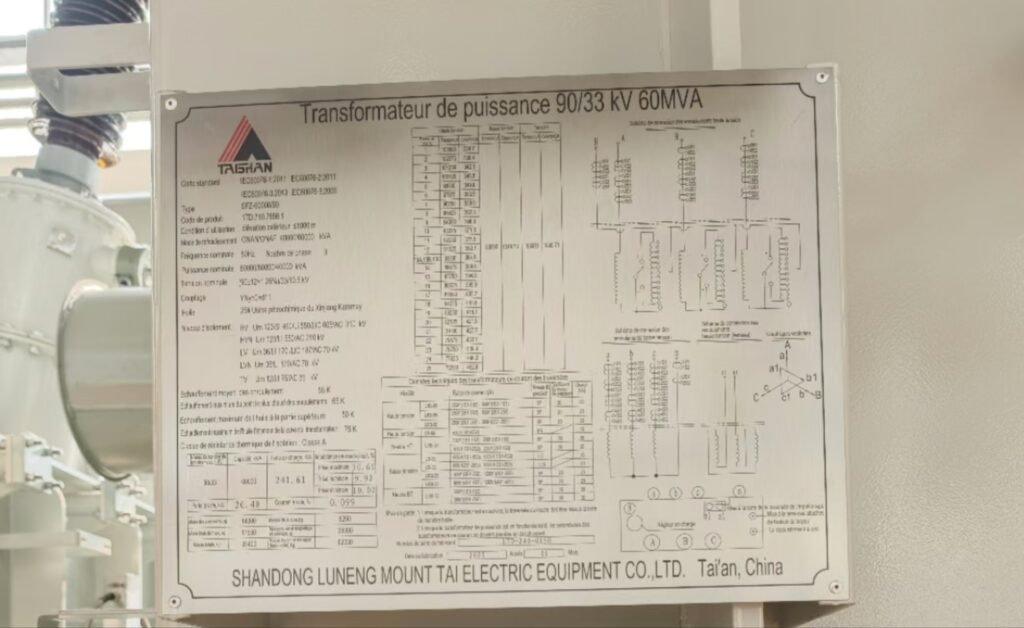
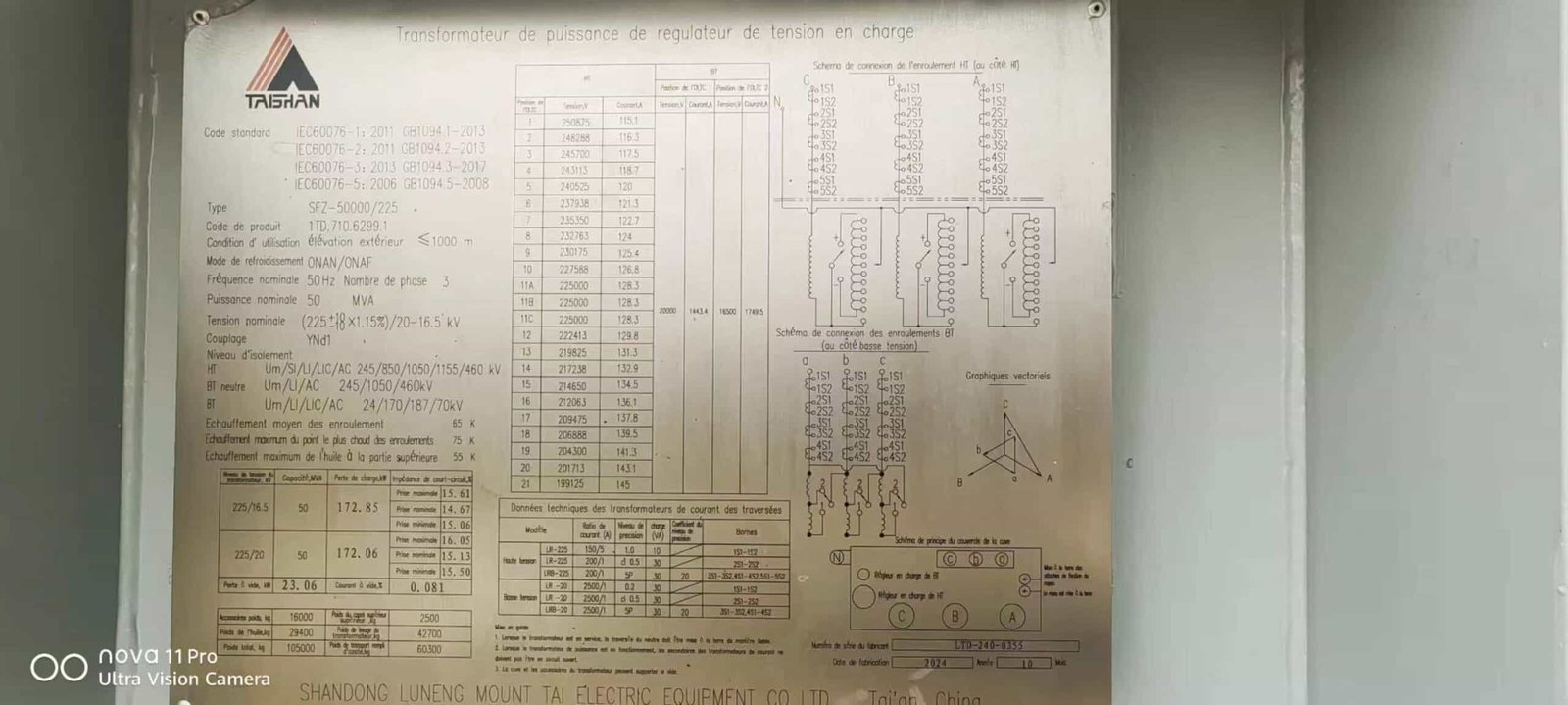
2. Example Nameplate and Interpretation
| Parameter | Example Value | Interpretation |
|---|---|---|
| kVA Rating | 2000 kVA | Can supply up to 2 MVA continuously. |
| Primary Voltage | 13.8 kV | Connect to 13.8 kV feeder. |
| Secondary Voltage | 480 V | Output to LV distribution panel. |
| Frequency | 60 Hz | Designed for North American grid. |
| Impedance | 5.75% | Limits fault current magnitude. |
| Cooling Class | ONAN/ONAF | Can operate with or without forced air. |
| Temp Rise | 65°C | Designed for continuous load within this limit. |
| Connection Type | Delta-Wye | Provides neutral point for grounding. |
3. Reading and Using the Data
- Load Planning: Use kVA and temperature rise to determine safe load sharing.
- Protection Coordination: Use impedance to size fuses/breakers correctly.
- Maintenance: Manufacturer and serial help source correct spare parts.
- System Matching: Voltage and connection type must align with system design.
4. Compliance and Standards
Transformer nameplates are designed according to IEEE C57, IEC 60076, or ANSI standards, ensuring international compatibility and safety compliance.
What Does the Power Rating (kVA/MVA) on a Transformer Mean?
In transformer selection and operation, the power rating is one of the most important parameters to understand. Choosing a transformer without correctly matching its kVA/MVA rating to the load demand can result in overheating, insulation damage, and reduced service life, while oversizing unnecessarily increases purchase and installation costs. The rating is essentially the transformer's safe continuous power-handling capability, set by its thermal limits and cooling method.
The power rating of a transformer, expressed in kilovolt-amperes (kVA) or megavolt-amperes (MVA), defines the maximum apparent power it can deliver continuously without exceeding its designed temperature rise, based on specified ambient conditions and cooling class. It reflects the combined limits of conductor cross-sectional area, core size, insulation class, and cooling capacity, rather than real power (kW) alone.
By knowing the power rating, operators can accurately size transformers to match load demand, avoid overload conditions, and ensure optimal efficiency throughout its lifecycle.
The kVA rating of a transformer indicates its real power capacity in kilowatts (kW).False
The kVA rating measures apparent power (combination of real and reactive power), not just real power. The real power in kW depends on the power factor of the connected load.
1. Understanding kVA vs. MVA
- kVA (kilovolt-amperes) = 1,000 volt-amperes, common for small-to-medium transformers.
- MVA (megavolt-amperes) = 1,000,000 volt-amperes, used for large utility and industrial transformers.
- The choice depends purely on capacity scale — the calculation principles are identical.
2. Relationship Between Load and Power Rating
| Parameter | Formula | Notes |
|---|---|---|
| Apparent Power (kVA) | Voltage (V) × Current (A) ÷ 1,000 | Single-phase |
| Apparent Power (kVA) | √3 × Voltage (V) × Current (A) ÷ 1,000 | Three-phase |
| Real Power (kW) | kVA × Power Factor (PF) | Depends on load type |
| Load Planning | Total load in kVA should not exceed transformer rating | Ensures thermal safety |
3. Thermal Design and Rating Limits
A transformer’s rating is set so that winding and core temperatures stay within insulation class limits. Factors include:
- Winding size & conductor material (affects current capacity)
- Core cross-section & steel quality (affects magnetic flux)
- Cooling method (ONAN, ONAF, OFAF, etc.)
- Ambient temperature (standards assume 20–40°C)
- Insulation class (e.g., Class A, B, F, H)
4. Example kVA Rating Calculation
| Transformer Type | Primary Voltage | Secondary Voltage | Full Load Current | kVA Rating |
|---|---|---|---|---|
| Single-phase | 11,000 V | 415 V | 10.5 A | 115.5 kVA |
| Three-phase | 33,000 V | 11,000 V | 315 A | 6,000 kVA (6 MVA) |
5. Practical Considerations in Selection
- Diversity Factor: If loads don’t operate simultaneously, a smaller kVA may suffice.
- Future Expansion: Consider growth to avoid early replacement.
- Load Type: Motor loads with low power factors require higher kVA ratings.
- Duty Cycle: Continuous vs. intermittent operation impacts rating requirements.
What Do Voltage Ratings and Tap Range on a Transformer Nameplate Mean?
When engineers select or operate a transformer, voltage ratings and tap ranges are as critical as power ratings. Choosing a unit without matching voltage compatibility to the grid and load can cause overheating, insulation stress, or unstable voltage supply. Furthermore, without correct tap settings, a transformer may fail to regulate voltage during supply variations, potentially damaging sensitive equipment.
The voltage ratings on a transformer nameplate define the nominal input (primary) and output (secondary) voltages it is designed to handle under rated load, while the tap range indicates the adjustable percentage variation available on the winding to fine-tune the output voltage for changes in supply or load conditions.
By understanding both parameters, operators can ensure grid compatibility, voltage stability, and compliance with equipment requirements.
The tap range on a transformer allows voltage adjustments to compensate for supply fluctuations or voltage drop in the system.True
Tap changers adjust the effective turns ratio, enabling precise voltage control without changing the transformer itself.
1. Understanding Voltage Ratings
- Primary Voltage: The nominal voltage the transformer is designed to receive.
- Secondary Voltage: The nominal voltage the transformer delivers to the load.
- Phase Connection: Ratings apply for the intended winding configuration (delta, wye, zig-zag).
- Tolerances: ANSI and IEC standards specify permissible voltage deviations (typically ±5%).
2. Tap Range Explained
| Tap Position | Percentage Change | Example for 33 kV Primary | Effect |
|---|---|---|---|
| +5% | +5% | 34.65 kV | Increases output voltage |
| +2.5% | +2.5% | 33.825 kV | Slight increase |
| Nominal | 0% | 33 kV | Standard setting |
| -2.5% | -2.5% | 32.175 kV | Slight decrease |
| -5% | -5% | 31.35 kV | Reduces output voltage |
3. Types of Tap Changers
Off-Load Tap Changer (OLTC)
- Adjustment only when transformer is de-energized
- Common for distribution transformers
- Simpler and less expensive
On-Load Tap Changer (OLTC)
- Allows adjustment while energized
- Used in power transformers and critical supply networks
- Supports automatic voltage regulation (AVR) systems
4. Design Considerations for Tap Range
- Voltage regulation requirements of the network
- Expected supply fluctuation range
- Load sensitivity to voltage variations
- Impact on transformer impedance and losses
- Switching mechanism durability for OLTC
5. Example Nameplate Interpretation
| Parameter | Value | Meaning |
|---|---|---|
| Primary Voltage | 33 kV | Nominal input voltage |
| Secondary Voltage | 11 kV | Nominal output voltage |
| Tap Range | ±5% in 2.5% steps | Allows fine adjustment |
| Tap Positions | 5 | +5%, +2.5%, 0%, -2.5%, -5% |
| Tap Changer Type | OLTC | On-load voltage adjustment possible |
What Do Frequency and Phase Configuration on a Transformer Nameplate Mean?

A mismatch in transformer frequency rating or phase configuration can cause overheating, core saturation, unstable operation, and even catastrophic failure. For example, operating a 50 Hz transformer on a 60 Hz supply without adjustments—or vice versa—can lead to reduced efficiency or insulation stress. Similarly, incorrect phase connection may result in incompatible voltage delivery and unbalanced loads.
The frequency rating on a transformer nameplate specifies the supply frequency (in hertz) it is designed for, while the phase configuration indicates whether it operates on single-phase or three-phase power and the winding connection arrangement between primary and secondary.
Correctly matching these parameters ensures that the transformer operates within design limits, delivering the expected voltage and power without overheating or inefficiency.
A 50 Hz transformer can be used at 60 Hz without any design changes and with identical performance.False
A transformer designed for 50 Hz can often run at 60 Hz with reduced losses, but core size and impedance affect performance; the reverse (60 Hz to 50 Hz) usually requires derating to avoid overheating.
1. Frequency Rating
- Common Values: 50 Hz (most of the world) and 60 Hz (North America, parts of Asia)
- Impact on Core Design: Lower frequency requires a larger core to prevent magnetic saturation.
Interchangeability:
- 50 Hz → 60 Hz: Usually safe, possible efficiency improvement
- 60 Hz → 50 Hz: Requires derating, may overheat if run at full load
- Special Applications: 400 Hz for aerospace, naval, and some military systems (lighter cores).
2. Phase Configuration Basics
| Phase Type | Common Use | Voltage Delivery | Notes |
|---|---|---|---|
| Single-phase | Residential, light commercial | One voltage waveform | Simple, low power |
| Three-phase | Industrial, commercial grids | Three voltage waveforms, 120° apart | Higher power, smoother load |
3. Transformer Winding Connections
| Symbol | Connection Type | Description | Example Use |
|---|---|---|---|
| Y | Wye (Star) | Neutral point available, multiple voltages possible | Distribution transformers |
| Δ | Delta | No neutral, robust against unbalanced loads | Industrial supply |
| Yd11 | Wye-Delta | Step-down with phase shift | Power distribution |
| Dy1 | Delta-Wye | Step-up with phase shift | Transmission transformers |
4. Nameplate Example
| Parameter | Value | Meaning |
|---|---|---|
| Frequency | 60 Hz | Designed for North American grid |
| Phase | 3 | Three-phase transformer |
| Connection Symbol | Dyn11 | Delta primary, Wye secondary, 30° phase shift |
| Neutral Availability | Yes | Wye secondary provides neutral point |
5. Selection Considerations
- Match frequency exactly to avoid magnetic saturation or reduced performance.
- Ensure phase configuration matches system requirements and load type.
- For three-phase systems, verify connection symbol to ensure correct phase displacement.
- In mixed-frequency facilities (e.g., airports with 400 Hz and 50 Hz), use dedicated transformers.
What Do Cooling Methods and Temperature Rise on a Transformer Nameplate Mean?
One of the most common causes of transformer failure is overheating due to inadequate cooling. Every transformer generates heat from copper losses (load losses) and core losses (no-load losses). Without effective cooling, internal temperatures can exceed insulation limits, accelerating aging and potentially leading to catastrophic failure. Misunderstanding the cooling method or temperature rise rating on a nameplate can result in overloading or poor ventilation planning.
Cooling methods on a transformer nameplate indicate the system used to remove heat from the transformer windings and core, while the temperature rise rating specifies how much hotter than ambient the windings can safely operate at rated load.
Properly interpreting these ratings ensures correct transformer loading, cooling system design, and long-term reliability.
An ONAN transformer can operate at higher loads simply by adding fans without other modifications.False
Adding fans to a transformer not designed for ONAF cooling can cause uneven heat removal and may not meet design clearances or radiator specifications.
1. Cooling Method Codes
The IEC and IEEE standards define standardized abbreviations:
| Code | Meaning | Cooling Process | Typical Use |
|---|---|---|---|
| ONAN | Oil Natural Air Natural | Heat moves from windings to oil via natural convection, oil to air naturally | Distribution transformers |
| ONAF | Oil Natural Air Forced | Fans blow air over radiators to improve cooling | Medium/large power transformers |
| OFAF | Oil Forced Air Forced | Pumps circulate oil, fans cool air | High-capacity transformers |
| OFWF | Oil Forced Water Forced | Oil-to-water heat exchanger | Power stations, marine |
| AN | Air Natural | Dry-type, natural air cooling | Indoor small transformers |
| AF | Air Forced | Dry-type with forced air | Indoor with high load demand |
2. Temperature Rise Ratings
- Definition: Max allowable temperature rise above ambient (usually 40°C ambient reference).
Typical Values:
- Oil-immersed: 55°C or 65°C rise for windings.
- Dry-type: 80°C, 115°C, 150°C depending on insulation class.
- Example:
If ambient is 40°C and winding temperature rise is 65°C → winding operates at 105°C max. - Link to Insulation Life: Higher temperature shortens insulation life exponentially (rule of thumb: +6°C halves insulation life).
3. Example Nameplate Entry
| Parameter | Value | Meaning |
|---|---|---|
| Cooling Method | ONAN/ONAF | Natural oil-air cooling with optional forced-air fans |
| Winding Temp Rise | 65°C | Max over 40°C ambient |
| Top Oil Temp Rise | 60°C | Oil surface temp above ambient |
| Ambient Reference | 40°C | Design reference temperature |
4. Engineering Considerations
- Match cooling method to site conditions (ventilation, space, noise limits).
- Respect temperature rise limits to avoid accelerated insulation degradation.
- Ensure fan and pump systems (for ONAF, OFAF) have redundancy for reliability.
- For high altitude installations, derate cooling due to reduced air density.
5. Cooling Method vs. Load Capacity
| Cooling Method | Relative Capacity | Example Use Case |
|---|---|---|
| ONAN | 1.0 (base) | Rural distribution transformer |
| ONAF | 1.3–1.5× ONAN | Urban substation |
| OFAF | 1.5–2.0× ONAN | Industrial load centers |
| OFWF | 2.0+ × ONAN | Marine/offshore power |
What Do Insulation Class and Impedance Mean on a Transformer Nameplate?
Misinterpreting insulation class or impedance can lead to costly transformer failures, operational incompatibility, or non-compliance with electrical system requirements. The insulation class directly determines a transformer’s maximum safe operating temperature and thus its expected lifespan, while impedance affects fault current levels, voltage regulation, and parallel operation capability. Choosing the wrong ratings can cause accelerated insulation degradation, nuisance tripping, or unsafe fault currents.
The insulation class on a transformer nameplate indicates the maximum temperature the insulation system can withstand without unacceptable aging, while the impedance value (in %) represents the voltage drop across the transformer at rated load and affects short-circuit current and load sharing.
A higher insulation class always means the transformer can handle more electrical load.False
Higher insulation class means tolerance to higher temperature, not necessarily higher kVA load rating. Load rating depends on design, cooling, and other parameters.
1. Insulation Class
- Definition: Maximum allowable hot-spot temperature for insulation before rapid degradation.
- Common Classes (IEEE/IEC):
| Insulation Class | Max Hot-Spot Temp (°C) | Typical Temp Rise | Common Use |
|---|---|---|---|
| 105 (Class A) | 105 | 55°C | Small dry-type, control transformers |
| 120 (Class E) | 120 | 65°C | Older designs, motors |
| 130 (Class B) | 130 | 80°C | Distribution transformers |
| 155 (Class F) | 155 | 100°C | Industrial dry-type |
| 180 (Class H) | 180 | 125°C | Special high-temp environments |
| 220 (Class R) | 220 | 150°C | Traction, aerospace |
- Life Expectancy Rule: For every 6–8°C rise above class limit, insulation life roughly halves.
2. Impedance
- Definition: Voltage drop across transformer windings when delivering rated load, expressed as a percentage of rated voltage.
Typical Values:
- Distribution transformers: 4–6%
- Large power transformers: 8–12%
Effects of Impedance:
- Short-Circuit Current: Lower impedance → higher fault currents.
- Voltage Regulation: Higher impedance → larger voltage drop under load.
- Parallel Operation: Transformers must have closely matched impedance to share load evenly.
Short-Circuit Current Formula:
$$
I{sc} = \frac{I{rated}}{Z_{pu}}
$$
Example: 5% impedance means short-circuit current ≈ 20 × rated current.
3. Example Nameplate Entry
| Parameter | Value | Meaning |
|---|---|---|
| Insulation Class | 155°C | Class F, max hot-spot temp |
| Impedance | 6% | Limits short-circuit current to \~16.67 × rated current |
| Frequency | 60 Hz | Design frequency |
4. Engineering Considerations
- For Insulation: Select class based on environment, load profile, and expected overloads. Higher class may allow higher temp rise but costs more.
- For Impedance: Balance between short-circuit current control and voltage regulation. In critical systems, impedance coordination with protection devices is vital.
- Parallel Operation: Ensure impedance difference ≤10% for proper load sharing.
5. Comparison Table — Impact of Impedance
| Impedance (%) | Short-Circuit Multiple | Pros | Cons |
|---|---|---|---|
| 4% | 25 × rated current | Better voltage regulation | Higher fault current stress |
| 6% | 16.67 × rated current | Balanced compromise | Slightly more voltage drop |
| 10% | 10 × rated current | Limits fault currents | Larger voltage regulation drop |
Conclusion
Interpreting transformer ratings and specifications is more than reading numbers—it requires understanding the relationship between capacity, voltage, cooling, insulation, and impedance. Proper interpretation ensures the transformer is suitable for the intended application, operates within safe limits, and delivers reliable performance throughout its service life. A thorough grasp of these parameters also aids in maintenance planning, upgrades, and troubleshooting.
FAQ
Q1: What do transformer ratings mean?
Transformer ratings indicate the designed operational limits of a transformer, including voltage, current, kVA capacity, and frequency. These ratings ensure the transformer operates efficiently without overheating or overloading. Common ratings include primary and secondary voltage, frequency (usually 50 or 60 Hz), and power capacity in kVA.
Q2: How is a transformer’s kVA rating determined?
A transformer’s kVA rating is determined by the maximum voltage and current it can handle safely without exceeding thermal limits. It represents the total apparent power capacity, not just real power. Engineers calculate this using winding capacity, insulation rating, and cooling method.
Q3: Why is voltage rating important in transformers?
Voltage rating ensures that the transformer can handle the input and output voltages without insulation breakdown. Exceeding the rated voltage can cause overheating, insulation failure, and safety hazards. Voltage ratings are usually listed for both primary and secondary windings.
Q4: What role does efficiency play in transformer specifications?
Transformer efficiency indicates how much input power is converted into usable output power with minimal losses. Higher efficiency reduces energy waste and operating costs. Efficiency depends on design, core material, load conditions, and cooling system.
Q5: How do load capacity and duty cycle affect transformer selection?
Load capacity defines the maximum safe load a transformer can carry, while the duty cycle specifies how long it can sustain that load without overheating. Selecting a transformer with adequate capacity for continuous or intermittent loads prevents early failure.
References
IEEE - Transformer Ratings and Performance: https://ieeexplore.ieee.org
NEMA - Transformer Standards: https://www.nema.org
Electrical4U - Transformer Rating Explained: https://www.electrical4u.com
Energy.gov - Transformer Efficiency Standards: https://www.energy.gov
All About Circuits - Transformer Basics: https://www.allaboutcircuits.com
Engineering Toolbox - Transformer Data and Charts: https://www.engineeringtoolbox.com