Transformer windings insulation is a fundamental aspect of transformer design, directly affecting electrical safety, reliability, thermal performance, and service life. Proper insulation prevents short circuits between turns, windings, and the core, while also withstanding electrical stress, heat, and mechanical forces during normal operation and fault conditions. Different insulation systems are selected based on transformer type, voltage level, and application environment.
What Is the Purpose of Insulating Transformer Windings?
In power transformers, failures rarely begin with dramatic external damage; instead, they almost always originate deep inside the winding insulation system. When winding insulation fails, the consequences are immediate and severe: short circuits, fires, explosions, prolonged outages, environmental contamination, and irreversible asset loss. For utilities, industrial users, and infrastructure operators, the pain point is clear—without robust insulation, even the most advanced transformer design becomes unsafe, unreliable, and short-lived. Insulating transformer windings is therefore not a secondary design detail; it is the foundational safeguard that allows transformers to function safely, efficiently, and continuously under high electrical, thermal, and mechanical stress.
The purpose of insulating transformer windings is to electrically isolate conductors, control electric fields, prevent short circuits and breakdowns, ensure operational safety, enable voltage transformation, and preserve long-term reliability under electrical, thermal, and mechanical stress.
Without effective winding insulation, voltage transformation would be impossible, isolation would be lost, and transformer operation would pose unacceptable risks to people, equipment, and power systems.
Transformer insulation is not passive material—it is an engineered system that determines the transformer’s safety margin, lifespan, and performance.
Transformer winding insulation is the primary determinant of transformer reliability and service life.True Industry failure statistics consistently show that insulation degradation is the leading cause of transformer failures. Proper insulation of transformer windings enables safe voltage transformation and electrical isolation between circuits.True Insulation prevents conductive contact and controls electric fields, allowing different voltage levels to coexist safely within one transformer.
Enabling Electrical Isolation Between Windings
One of the most critical purposes of insulating transformer windings is electrical isolation.
Transformers rely on:
- Magnetic coupling
- Not direct electrical connection
Insulation ensures:
- No conductive path between primary and secondary windings
- Safe separation between different voltage levels
- Protection of downstream equipment and personnel
Without insulation, voltage transformation would collapse into a direct short circuit.
Preventing Short Circuits and Internal Faults
Transformer windings operate under high electrical stress.
Insulation prevents:
- Turn-to-turn short circuits
- Layer-to-layer faults
- Phase-to-phase breakdown
Even a microscopic insulation defect can escalate into catastrophic failure under operating voltage and thermal stress.
Controlling Electric Fields and Voltage Stress
Voltage stress is not evenly distributed.
Winding insulation is designed to:
- Control electric field gradients
- Prevent localized stress concentration
- Avoid partial discharge inception
Graded insulation systems are essential for high-voltage transformers.
Enabling Safe High-Voltage Operation
Transformers routinely operate at:
- Tens
- Hundreds
- Even thousands of kilovolts
Insulating windings allows:
- Compact design
- Safe high-voltage containment
- Compliance with clearance and creepage requirements
High-voltage operation without insulation is physically impossible.
Protecting Against Partial Discharge
Partial discharge is a major aging mechanism.
Insulation prevents:
- Void formation
- Gas pockets
- Surface discharges
By suppressing PD, insulation preserves dielectric integrity over decades of service.
Thermal Protection and Heat Management
Transformer windings generate heat.
Insulation systems are designed to:
- Withstand high operating temperatures
- Transfer heat to cooling media
- Maintain mechanical stability at elevated temperatures
Thermal endurance class directly determines insulation life.
| Insulation Class | Max Temperature (°C) | Typical Application |
|---|---|---|
| Class A | 105 | Older oil-paper systems |
| Class F | 155 | Dry-type transformers |
| Class H | 180 | High-performance dry-type units |
Mechanical Strength and Short-Circuit Withstand
Short-circuit forces are extreme.
Insulation contributes to:
- Mechanical spacing
- Structural integrity
- Resistance to axial and radial forces
Without mechanically robust insulation, windings would deform and fail during faults.
Ensuring Long-Term Reliability and Aging Resistance
Transformer insulation ages over time.
Insulation purpose includes:
- Slowing chemical degradation
- Resisting oxidation and moisture
- Maintaining dielectric strength over decades
A transformer’s life expectancy is essentially the life expectancy of its insulation system.
Preventing Fire and Explosion Hazards
Insulation failure can ignite oil or gases.
Proper insulation prevents:
- Internal arcing
- Oil decomposition
- Rapid pressure rise
Fire safety is a direct outcome of insulation integrity.
Supporting Efficiency and Performance Stability
Insulation affects losses indirectly.
Well-designed insulation:
- Maintains winding geometry
- Prevents hot spots
- Supports stable electrical parameters
This contributes to consistent efficiency over the transformer’s life.
Environmental Protection
Insulation failure often leads to oil leakage and contamination.
Insulation protects:
- Soil and groundwater
- Surrounding infrastructure
- Compliance with environmental regulations
Environmental risk control starts inside the winding insulation system.
Types of Transformer Winding Insulation
Transformer insulation is multi-layered.
Common materials include:
- Cellulose paper
- Pressboard
- Enamel coatings
- Epoxy resin
- Nomex and aramid papers
Each material serves a specific electrical, thermal, and mechanical function.
Oil-Immersed vs. Dry-Type Insulation Systems
Oil-immersed insulation:
- Uses oil as dielectric and coolant
- Relies on paper-oil synergy
Dry-type insulation:
- Uses resin or air
- Prioritizes fire safety and indoor use
Both systems depend on insulation integrity.
Insulation Coordination and Standards Compliance
Insulation is designed according to standards.
IEC and IEEE define:
- Insulation levels
- Test voltages
- Safety margins
Proper insulation ensures compliance and approval.
Role in Overvoltage and Transient Protection
Transformers face transient stress.
Insulation enables:
- Withstand of lightning impulses
- Resistance to switching surges
- Grid disturbance tolerance
Without insulation coordination, transients would cause immediate failure.
Impact on Maintenance and Diagnostics
Insulation condition determines maintenance strategy.
Monitoring focuses on:
- Dissolved gas analysis
- Partial discharge measurement
- Moisture content
All diagnostics revolve around insulation health.
Economic Importance of Insulation
Insulation quality affects total cost of ownership.
Good insulation:
- Extends service life
- Reduces outages
- Minimizes replacement cost
Poor insulation multiplies lifetime expenses.
Case Example: Insulation Failure Consequences
Industry case studies show:
- Minor insulation defects causing major blackouts
- Multi-million-dollar losses from single insulation failure
- Long outage recovery times
These failures underline insulation’s critical purpose.
Role in Renewable and Modern Power Systems
Renewable integration increases stress.
Insulation must handle:
- Voltage fluctuations
- Frequent switching
- Harmonics
Modern insulation systems enable grid flexibility.
Net-Zero and Sustainability Implications
Longer insulation life reduces:
- Resource consumption
- Carbon footprint
- Waste generation
Sustainable power systems depend on durable insulation.
Why Insulation Design Is a Core Engineering Discipline
Insulation design requires:
- Electrical engineering
- Materials science
- Thermal analysis
- Mechanical modeling
It is one of the most complex aspects of transformer engineering.
What Insulation Materials Are Commonly Used in Transformer Windings?

In transformer engineering, winding insulation is not a single material but a carefully engineered system made up of multiple complementary materials. The pain point for utilities, OEMs, and industrial users is that insulation failure remains the leading cause of transformer breakdowns, fires, and premature aging. Once insulation degrades, repair is often impossible without full replacement of the transformer. The consequence is high financial loss, long outages, and safety risks. Selecting the right insulation materials—matched to voltage level, thermal class, cooling method, and operating environment—is therefore one of the most critical decisions in transformer design. Understanding which insulation materials are commonly used, and why, is essential for ensuring safe, long-lasting, and efficient transformer operation.
Transformer windings commonly use insulation materials such as cellulose paper, pressboard, mineral oil, synthetic ester oil, enamel coatings, epoxy resin, and high-performance aramid papers, each selected to provide electrical insulation, thermal endurance, mechanical strength, and long-term reliability.
Transformer insulation is never accidental. Every material plays a defined role in managing electrical stress, heat, moisture, and mechanical forces over decades of continuous operation.
Cellulose-based insulation remains the most widely used winding insulation material in power transformers worldwide.True
Paper-oil insulation systems offer proven dielectric strength, thermal performance, and long-term reliability for oil-immersed transformers.
High-performance synthetic insulation materials significantly extend transformer operating temperature limits and service life.True
Materials such as aramid paper and epoxy resin withstand higher temperatures and slower aging than traditional cellulose alone.
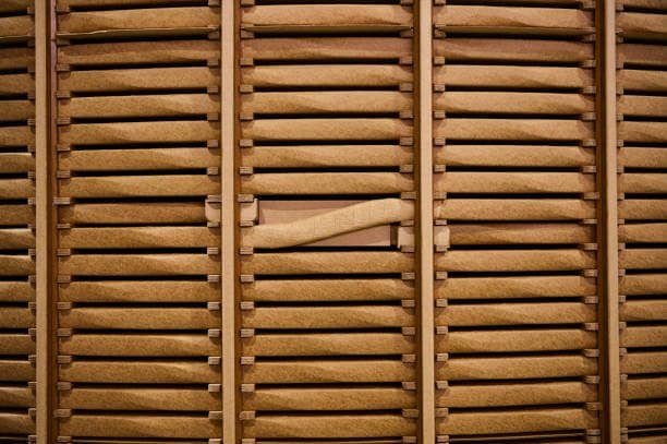
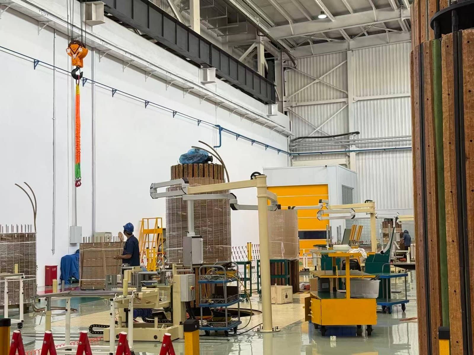
Cellulose Paper Insulation
Cellulose paper is the foundation of traditional transformer insulation systems.
It is widely used because:
- Excellent dielectric strength
- Good thermal conductivity
- Compatibility with insulating oils
- Proven performance over decades
Cellulose paper is wrapped around:
- Individual conductors
- Turns
- Layers
In oil-immersed transformers, paper absorbs oil, creating a composite insulation system with enhanced dielectric and cooling performance.
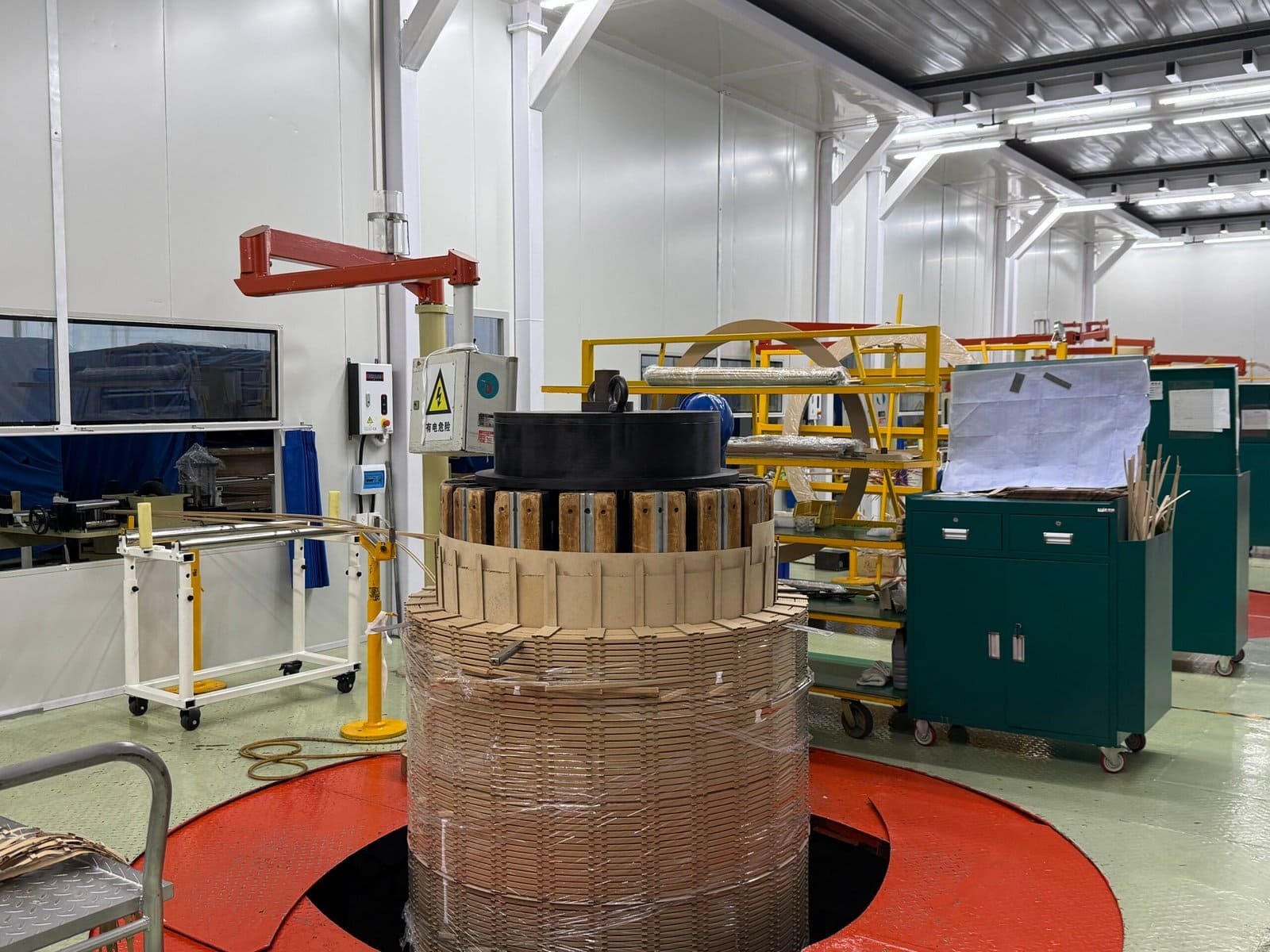
Pressboard and Cellulose-Based Structural Insulation
Pressboard is a thicker, mechanically stronger form of cellulose insulation.
It is commonly used for:
- Spacers between winding layers
- Barriers between windings
- Structural supports inside the transformer
Pressboard provides:
- Mechanical rigidity
- Controlled electrical clearances
- Resistance to short-circuit forces
Without pressboard, windings would deform under electrical fault stress.
Mineral Oil as Liquid Insulation
Mineral oil is one of the most important insulating materials in oil-immersed transformers.
Its functions include:
- Electrical insulation
- Heat dissipation
- Arc suppression
Oil fills voids in solid insulation, increasing dielectric strength and reducing partial discharge risk.
| Property | Mineral Oil Role |
|---|---|
| Dielectric strength | Prevents breakdown |
| Thermal conductivity | Removes heat |
| Fluidity | Fills insulation gaps |
Mineral oil works synergistically with paper insulation.
Synthetic Ester and Natural Ester Oils
Modern transformers increasingly use ester-based insulating liquids.
Advantages include:
- Higher fire point
- Better biodegradability
- Improved moisture tolerance
Ester oils:
- Extend insulation life
- Reduce environmental risk
- Improve fire safety
They are especially common in urban, renewable, and environmentally sensitive installations.
Enamel (Varnish) Coatings on Conductors
Each copper conductor is typically coated with enamel insulation.
Enamel provides:
- Turn-to-turn insulation
- Smooth surface finish
- Resistance to abrasion
This thin insulation layer prevents immediate short circuits between adjacent turns.
Epoxy Resin Insulation Systems
Epoxy resin is the dominant insulation material in dry-type transformers.
Epoxy systems:
- Encapsulate windings
- Eliminate liquid insulation
- Improve fire resistance
They provide:
- High dielectric strength
- Excellent mechanical stability
- Resistance to moisture and pollution
Epoxy insulation is common in:
- Indoor transformers
- Buildings
- Industrial facilities
Aramid Paper (Nomex® and Similar Materials)
Aramid paper is a high-performance insulation material.
Key properties:
- High thermal class (up to 220°C)
- Excellent mechanical strength
- Resistance to aging
Aramid paper is used when:
- Higher loading is required
- Compact designs are needed
- Long life under high temperature is critical
It is often combined with oil or resin systems.
Polyester and Polyimide Films
Thin polymer films are used in specific applications.
They provide:
- Precise dielectric spacing
- Flexibility
- High breakdown voltage
These films are common in:
- Layer insulation
- Lead insulation
- Special winding configurations
Nominal Thermal Classes of Common Insulation Materials
| Material | Thermal Class (°C) | Typical Application |
|---|---|---|
| Cellulose paper | 105–120 | Oil-immersed windings |
| Mineral oil | 105 | Cooling and insulation |
| Ester oil | 120–140 | Fire-safe transformers |
| Epoxy resin | 155–180 | Dry-type transformers |
| Aramid paper | 180–220 | High-temperature designs |
Thermal class directly affects transformer lifespan.
Composite Insulation Systems
No transformer uses a single insulation material.
Instead, insulation systems combine:
- Solid insulation
- Liquid insulation
- Gaseous or resin components
This composite approach:
- Distributes electrical stress
- Enhances cooling
- Improves mechanical integrity
System design is more important than any single material.
Role of Insulation Materials in Partial Discharge Control
Partial discharge is a major aging mechanism.
Proper insulation materials:
- Minimize voids
- Reduce gas formation
- Smooth electric field gradients
Advanced materials significantly lower PD inception levels.
Mechanical Strength Under Short-Circuit Conditions
Short-circuit forces are extreme.
Insulation materials must:
- Maintain spacing
- Resist compression and tension
- Prevent winding movement
Mechanical failure often begins in weak insulation materials.
Moisture Resistance and Aging Behavior
Moisture accelerates insulation aging.
Material selection considers:
- Moisture absorption
- Drying capability
- Long-term chemical stability
Ester oils and aramid papers improve moisture tolerance.
Environmental and Fire Safety Considerations
Insulation materials influence fire risk.
Modern trends favor:
- High fire point liquids
- Non-toxic materials
- Biodegradable insulation
These choices reduce environmental impact and improve safety.
Standards Governing Insulation Materials
IEC and IEEE standards define:
- Material properties
- Test requirements
- Safety margins
Compliance ensures predictable performance.
Impact on Maintenance and Diagnostics
Insulation materials determine monitoring strategy.
Common diagnostics include:
- Dissolved gas analysis
- Moisture measurement
- Partial discharge testing
All focus on insulation condition.
Cost vs. Performance Trade-Offs
Advanced materials cost more upfront.
However, they:
- Extend service life
- Allow higher loading
- Reduce failure risk
Lifecycle cost is often lower despite higher initial price.
Case Insight: Insulation Material Upgrade
Utilities upgrading from mineral oil and cellulose to ester-aramid systems report:
- Longer insulation life
- Improved fire safety
- Reduced environmental risk
Material choice has strategic impact.
Role in Renewable and Modern Grid Applications
Renewable integration increases stress.
Advanced insulation materials handle:
- Voltage fluctuations
- Frequent load cycling
- Higher harmonics
Modern grids demand better insulation systems.
Net-Zero and Sustainability Impact
Durable insulation reduces:
- Transformer replacement frequency
- Resource consumption
- Carbon footprint
Material choice directly supports sustainability goals.
Why Insulation Material Selection Is a Core Design Decision
Choosing insulation materials requires:
- Electrical engineering
- Thermal modeling
- Mechanical analysis
- Environmental assessment
It is one of the most critical design steps.
How Are Low-Voltage and High-Voltage Windings Insulated Differently?
In transformer failures investigated worldwide, insulation breakdown almost never occurs uniformly across the windings—it overwhelmingly initiates in high-voltage regions where electric stress, partial discharge, and thermal aging concentrate. The pain point for utilities and industrial operators is that low-voltage (LV) and high-voltage (HV) windings are often misunderstood as being insulated “more or less the same,” leading to incorrect specifications, unrealistic expectations, or improper maintenance strategies. The consequence is premature insulation aging, commissioning failures, or catastrophic breakdowns that could have been prevented through proper insulation differentiation. In reality, LV and HV windings are insulated using fundamentally different philosophies, materials, thicknesses, and electric field control techniques because they operate under completely different electrical stress regimes.
Low-voltage windings are insulated primarily for current density, thermal endurance, and mechanical strength, while high-voltage windings require multilayer, graded insulation systems designed to withstand extreme electric field stress, overvoltages, and long-term dielectric aging.
Understanding these differences is essential for anyone involved in transformer design, specification, operation, or asset management.
Transformer insulation is not about “more insulation everywhere,” but about the right insulation in the right place.
High-voltage winding insulation is designed primarily to control electric field stress rather than only to prevent direct short circuits.True
At high voltages, electric field distribution and partial discharge prevention are more critical than conductor-to-conductor contact alone.
Low-voltage winding insulation failures are more often driven by thermal and mechanical stress than by dielectric breakdown.True
LV windings operate at lower electric stress but higher current and mechanical forces, making thermal aging and deformation dominant failure mechanisms.
Fundamental Difference in Electrical Stress Levels
The most important distinction between LV and HV winding insulation is the magnitude and nature of electrical stress.
Low-voltage windings:
- Operate at relatively low electric field intensity
- Experience high current levels
- Face minimal overvoltage stress
High-voltage windings:
- Operate under intense electric field gradients
- Must withstand lightning and switching impulses
- Are highly sensitive to insulation geometry and material interfaces
This fundamental difference drives all insulation design decisions.
Insulation Objectives for Low-Voltage Windings
LV winding insulation focuses on robustness rather than thickness.
Primary objectives include:
- Turn-to-turn insulation
- Thermal endurance under high current load
- Mechanical stability under short-circuit forces
LV insulation is designed to survive heating and movement rather than extreme voltage stress.
Insulation Objectives for High-Voltage Windings
HV winding insulation is primarily dielectric in nature.
Its objectives include:
- Withstanding high steady-state voltage
- Managing electric field distribution
- Preventing partial discharge and tracking
- Surviving transient overvoltages
HV insulation design is a specialized discipline involving electric field modeling and stress grading.
Thickness and Layering Differences
One of the most visible differences is insulation thickness.
Low-voltage windings:
- Use thin insulation layers
- Typically rely on enamel coatings and thin paper
- Have minimal radial insulation
High-voltage windings:
- Use multiple layers of paper, pressboard, and oil gaps
- Have significant radial and axial insulation
- Include insulation barriers and spacers
| Winding Type | Insulation Thickness | Design Priority |
|---|---|---|
| Low-voltage | Thin | Thermal & mechanical |
| High-voltage | Thick & graded | Dielectric strength |
Materials Used in Low-Voltage Winding Insulation
LV windings typically use simpler insulation systems.
Common materials include:
- Enamel-coated copper conductors
- Thin cellulose paper wraps
- Polyester or polyimide films
These materials provide adequate dielectric strength at low voltage while maximizing heat transfer.
Materials Used in High-Voltage Winding Insulation
HV windings require complex composite insulation systems.
They commonly include:
- Multiple layers of cellulose paper
- Pressboard cylinders and barriers
- Oil-impregnated insulation
- Aramid paper in high-performance designs
Material purity and moisture control are critical for HV insulation reliability.
Electric Field Control and Grading
Electric field control is largely irrelevant for LV windings but critical for HV windings.
HV insulation uses:
- Graded insulation thickness
- Capacitive field control
- Smooth electrode shapes
These techniques prevent local stress concentration that would otherwise initiate partial discharge.
Role of Oil in HV vs. LV Insulation
Oil plays a much larger role in HV insulation systems.
In LV windings:
- Oil mainly provides cooling
- Dielectric function is secondary
In HV windings:
- Oil fills insulation gaps
- Increases dielectric strength
- Suppresses partial discharge
The oil-paper system is fundamental to HV insulation performance.
Partial Discharge Sensitivity
Partial discharge behavior differs dramatically.
Low-voltage windings:
- Rarely experience PD
- Fail mainly due to overheating or mechanical damage
High-voltage windings:
- Extremely sensitive to PD
- PD accelerates insulation aging
- PD control is a core design requirement
Mechanical Stress and Insulation Design
Mechanical forces differ between LV and HV windings.
LV windings:
- Carry higher current
- Experience stronger electromagnetic forces
- Require mechanically tough insulation
HV windings:
- Carry lower current
- Experience lower mechanical force
- Require precise spacing and rigidity
Insulation systems are optimized accordingly.
Thermal Aging Characteristics
Thermal stress affects LV and HV insulation differently.
LV insulation:
- Operates closer to thermal limits
- Aging driven by temperature rise
HV insulation:
- Often operates cooler
- Aging driven by electrical stress and moisture
This difference influences material selection and cooling design.
Insulation Geometry and Winding Arrangement
Winding placement reflects insulation needs.
Typically:
- LV winding is placed closer to the core
- HV winding is placed outside
This arrangement:
- Reduces insulation stress to ground
- Simplifies insulation coordination
HV windings require more space and complex insulation geometry.
Radial and Axial Insulation Requirements
HV windings require both:
- Radial insulation to ground
- Axial insulation between turns and layers
LV windings often require minimal radial insulation.
Overvoltage and Impulse Withstand
Impulse stress defines HV insulation.
HV windings must withstand:
- Lightning impulses
- Switching surges
LV windings are rarely exposed to such stress.
Testing Differences Reflect Insulation Design
Factory tests differ significantly.
LV windings:
- Tested mainly for resistance and temperature rise
HV windings:
- Subjected to high-voltage withstand tests
- Impulse tests
- Partial discharge measurements
Testing reflects insulation complexity.
Moisture Sensitivity
HV insulation is far more sensitive to moisture.
Even small moisture increases:
- Reduce dielectric strength
- Increase PD risk
LV insulation is more tolerant but still affected thermally.
Insulation Aging and Failure Modes
Failure modes differ:
LV winding failures:
- Overheating
- Mechanical deformation
- Insulation abrasion
HV winding failures:
- Partial discharge erosion
- Electrical breakdown
- Surface tracking
Understanding these modes is critical for diagnostics.
Maintenance and Monitoring Implications
Monitoring focuses differently:
LV insulation:
- Temperature monitoring
- Load management
HV insulation:
- Dissolved gas analysis
- PD monitoring
- Moisture measurement
Asset management strategies differ accordingly.
Standards and Design Margins
IEC and IEEE standards clearly differentiate:
- LV insulation levels
- HV insulation levels
HV windings require far larger safety margins.
Cost and Design Trade-Offs
HV insulation:
- Higher material cost
- More manufacturing complexity
LV insulation:
- Lower cost
- Higher emphasis on thermal performance
Optimizing both is key to transformer economics.
Case Insight: Misapplied Insulation Design
Industry failure investigations show that:
- Under-designed HV insulation leads to early failure
- Over-insulating LV windings increases losses and cost
Correct differentiation is essential.
Impact on Transformer Size and Weight
HV insulation significantly increases:
- Transformer size
- Weight
LV insulation has minimal impact on overall dimensions.
Role in Renewable and Modern Grids
Modern grids stress HV insulation more due to:
- Frequent switching
- Voltage fluctuations
- Harmonics
LV insulation stress remains mostly thermal.
Sustainability Considerations
HV insulation durability:
- Extends transformer life
- Reduces replacement frequency
This directly supports sustainability and net-zero goals.
Why Engineers Treat LV and HV Insulation Separately
Insulation design teams treat LV and HV windings as separate engineering problems.
Because:
- Stress mechanisms differ
- Failure consequences differ
- Optimization criteria differ
This separation is fundamental to transformer reliability.
How Does Insulation Handle Thermal and Electrical Stress?
In transformer operation, insulation is constantly under attack from two invisible but relentless forces: heat and electricity. The pain point faced by utilities, industrial operators, and grid designers is that insulation failure does not occur suddenly without cause—it is the cumulative result of thermal overload, electrical overstress, moisture ingress, and aging mechanisms acting together over time. When insulation can no longer withstand these stresses, the consequences are severe: winding short circuits, catastrophic breakdown, fires, long outages, and irreversible asset loss. The solution lies in understanding how transformer insulation systems are specifically engineered to manage, distribute, and survive both thermal and electrical stress throughout decades of continuous service.
Transformer insulation handles thermal stress by dissipating heat, maintaining mechanical stability at elevated temperatures, and resisting chemical aging, while it handles electrical stress by controlling electric field distribution, preventing partial discharge, and providing sufficient dielectric strength against steady-state and transient voltages.
Insulation is not passive material—it is an active, engineered defense system that allows transformers to operate safely under extreme physical conditions.
The performance of a transformer over its entire lifecycle is, in practical terms, the performance of its insulation under thermal and electrical stress.
Thermal and electrical stress acting together are the primary causes of long-term insulation aging in power transformers.True Heat accelerates chemical degradation while electrical stress promotes partial discharge and breakdown, making their combined effect the dominant aging mechanism. Properly designed insulation systems can withstand continuous thermal and electrical stress for 30–50 years of transformer service life.True IEC/IEEE-compliant insulation systems are engineered with safety margins that allow decades of reliable operation under rated conditions.
Understanding Thermal Stress in Transformer Insulation
Thermal stress arises from heat generated during normal operation.
Primary heat sources include:
- Copper (load) losses in windings
- Core (no-load) losses
- Stray losses from leakage flux
This heat continuously challenges the insulation system.
Thermal stress is cumulative—every degree of temperature rise accelerates insulation aging.
How Insulation Manages Heat Dissipation
Insulation materials are selected not only for dielectric strength but also for thermal performance.
They manage heat by:
- Conducting heat away from windings
- Transferring heat to cooling media (oil or air)
- Maintaining structural integrity at high temperature
Oil-impregnated paper insulation is particularly effective because oil improves both dielectric and thermal conductivity.
Thermal Classes and Temperature Limits
Insulation materials are rated by thermal class.
| Insulation Class | Max Operating Temperature (°C) | Typical Materials |
|---|---|---|
| Class A | 105 | Cellulose paper, mineral oil |
| Class F | 155 | Epoxy resin, polyester |
| Class H | 180 | Silicone, aramid paper |
| Class R | 220 | Advanced aramid systems |
Operating beyond these limits dramatically shortens insulation life.
Thermal Aging Mechanisms
Heat causes chemical reactions within insulation.
Key aging mechanisms include:
- Oxidation
- Depolymerization of cellulose
- Loss of mechanical strength
- Reduced dielectric capability
For cellulose insulation, the rate of aging roughly doubles for every 6–8°C increase in temperature.
Moisture, Heat, and Insulation Degradation
Thermal stress interacts strongly with moisture.
Higher temperatures:
- Increase moisture mobility
- Reduce dielectric strength
- Accelerate chemical aging
Modern insulation systems are designed to tolerate limited moisture while minimizing its impact.
Electrical Stress and Dielectric Requirements
Electrical stress arises from voltage differences within the transformer.
Sources include:
- Normal operating voltage
- Overvoltages
- Lightning impulses
- Switching surges
Insulation must withstand both continuous and transient electrical stress.
How Insulation Controls Electric Fields
Electrical stress is not evenly distributed.
Insulation systems manage electric fields by:
- Grading insulation thickness
- Using barriers and spacers
- Controlling geometry of conductors
This prevents localized stress concentration that would initiate breakdown.
Role of Dielectric Strength
Dielectric strength defines how much voltage insulation can withstand.
Insulation materials are chosen to:
- Exceed rated voltage requirements
- Maintain margins under aging
- Withstand impulse voltages
High-voltage windings rely on composite oil-paper systems to achieve very high dielectric strength.
Partial Discharge Suppression
Partial discharge (PD) is one of the most damaging electrical stress mechanisms.
Insulation handles PD by:
- Eliminating voids and gas pockets
- Using oil or resin impregnation
- Smoothing electric field gradients
Suppressing PD is essential for long-term insulation survival.
Electrical Stress in Low-Voltage vs. High-Voltage Windings
Electrical stress differs significantly by winding type.
Low-voltage windings:
- Experience lower electric fields
- Face minimal PD risk
- Are dominated by thermal stress
High-voltage windings:
- Experience intense electric fields
- Are highly PD-sensitive
- Require complex insulation grading
Insulation design reflects these differences.
Interaction of Thermal and Electrical Stress
Thermal and electrical stresses do not act independently.
Heat:
- Reduces dielectric strength
- Accelerates PD damage
- Weakens mechanical structure
Electrical stress:
- Generates localized heating
- Promotes insulation erosion
Their interaction defines insulation lifetime.
Mechanical Stability Under Combined Stress
Thermal expansion and electrical forces cause movement.
Insulation must:
- Maintain spacing under expansion
- Resist deformation during short circuits
- Preserve geometry over time
Mechanical failure often precedes electrical breakdown.
Oil’s Dual Role in Stress Management
In oil-immersed transformers, oil is essential.
Oil:
- Removes heat
- Increases dielectric strength
- Suppresses PD
Degraded oil directly reduces insulation’s ability to handle stress.
Dry-Type Insulation Stress Management
Dry-type insulation systems use resin and air.
They handle stress by:
- Encapsulating windings
- Eliminating moisture
- Using high thermal class materials
Fire safety improves, but thermal margins must be carefully managed.
Stress During Abnormal Conditions
Insulation must survive abnormal events.
These include:
- Overloading
- Short circuits
- Voltage surges
Design margins ensure insulation survives occasional stress without immediate failure.
Testing to Verify Stress Withstand Capability
Factory tests simulate stress conditions.
These include:
- Temperature rise tests
- High-voltage withstand tests
- Impulse tests
- Partial discharge tests
Testing confirms insulation performance before service.
Monitoring Stress During Service Life
Modern transformers monitor insulation stress indirectly.
Common methods:
- Temperature sensors
- Dissolved gas analysis
- Moisture measurement
- PD monitoring
Monitoring allows stress to be managed before failure occurs.
Impact of Stress on Insulation Life Expectancy
Insulation life is finite.
Excessive stress:
- Accelerates aging
- Reduces safety margins
- Increases failure probability
Managing stress is the key to life extension.
Role of Design Margins and Standards
IEC and IEEE standards define:
- Maximum temperatures
- Insulation levels
- Test voltages
Design margins ensure insulation survives real-world stress variability.
Advanced Materials for Stress Resistance
Modern insulation materials improve stress handling.
Examples include:
- Aramid paper for high temperature
- Ester oils for moisture tolerance
- Advanced epoxy systems for dry-type units
These materials extend stress tolerance limits.
Sustainability and Stress Management
Better stress handling:
- Extends transformer life
- Reduces replacement frequency
- Lowers environmental impact
Insulation durability supports net-zero goals.
Case Insight: Stress-Induced Insulation Failure
Industry failure analyses show:
- Chronic overheating drastically shortens insulation life
- Small PD activity leads to catastrophic failure over time
These cases underline the importance of stress management.
Why Insulation Design Is a Multidisciplinary Task
Handling thermal and electrical stress requires:
- Electrical engineering
- Thermal analysis
- Materials science
- Mechanical design
Insulation design integrates all disciplines.
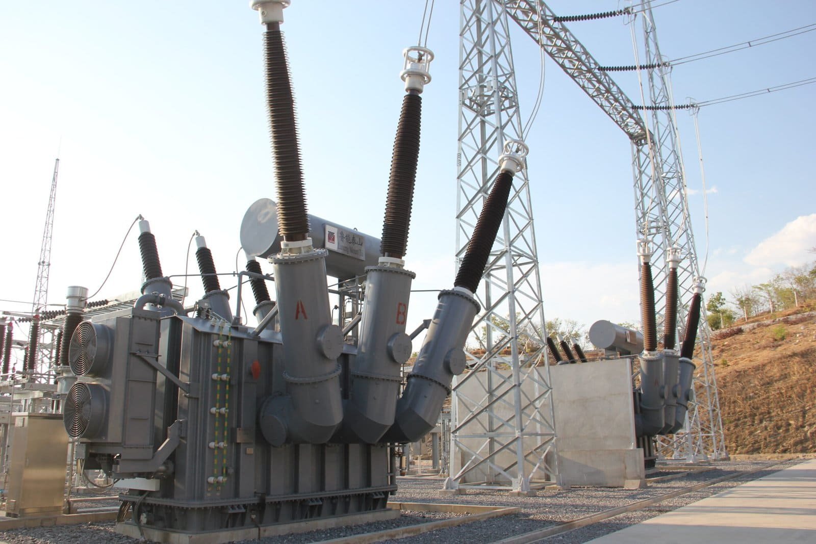
What Is the Difference Between Dry-Type and Oil-Immersed Winding Insulation?
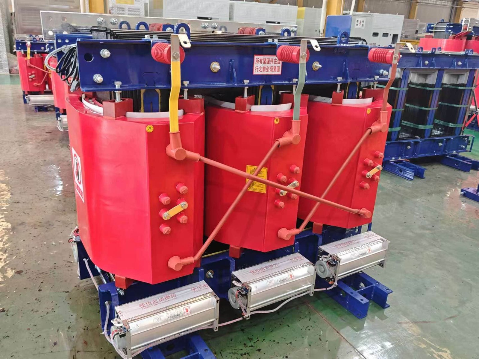
In transformer projects, one of the most consequential decisions engineers and asset owners face is choosing between dry-type and oil-immersed winding insulation. The pain point is that this choice is often simplified to “oil versus no oil,” ignoring the deep technical differences in insulation behavior, thermal performance, aging mechanisms, fire safety, maintenance philosophy, and lifetime cost. The consequence of a poorly matched insulation system can be overheating, premature insulation aging, regulatory non-compliance, or unnecessary capital and operating expense. Understanding the true difference between dry-type and oil-immersed winding insulation is therefore essential for making safe, reliable, and economically sound transformer decisions.
The fundamental difference between dry-type and oil-immersed winding insulation is that dry-type insulation relies on solid materials and air for dielectric and thermal performance, while oil-immersed insulation uses a composite paper–oil system where liquid oil provides both electrical insulation and active cooling.
This distinction drives nearly every aspect of transformer design, application, and lifecycle behavior.
Oil-immersed transformer insulation systems provide higher dielectric strength and superior cooling compared to dry-type insulation systems.True The oil-paper composite system enhances heat dissipation and electric field control, allowing higher power density and voltage ratings. Dry-type transformer insulation offers improved fire safety and lower environmental risk in indoor installations.True Dry-type insulation eliminates flammable liquid, reducing fire propagation and oil leakage hazards.
Fundamental Insulation System Philosophy
The difference begins with insulation philosophy.
Dry-type transformers:
- Use solid insulation only
- Rely on air or forced air for cooling
- Eliminate liquid dielectric materials
Oil-immersed transformers:
- Use composite insulation systems
- Combine solid cellulose insulation and liquid oil
- Integrate insulation and cooling into one system
This philosophical difference determines performance limits.
Insulation Materials Used in Each System
The insulation materials differ significantly.
Dry-type winding insulation typically includes:
- Epoxy resin (cast resin)
- Polyester or epoxy varnish
- Aramid paper (Nomex®)
- Fiberglass reinforcement
Oil-immersed winding insulation typically includes:
- Cellulose paper
- Pressboard barriers
- Mineral oil, natural ester, or synthetic ester fluids
These material sets behave very differently under stress.
Dielectric Strength and Voltage Capability
Dielectric performance is one of the most important differences.
Oil-immersed insulation:
- Achieves very high dielectric strength
- Oil fills microscopic voids
- Strongly suppresses partial discharge
Dry-type insulation:
- Relies on solid dielectric only
- More sensitive to voids and defects
- Lower maximum voltage capability
This is why extra-high-voltage transformers are almost exclusively oil-immersed.
Thermal Performance and Heat Dissipation
Cooling is inseparable from insulation performance.
Oil-immersed insulation:
- Uses oil as a heat transfer medium
- Circulates heat efficiently to radiators
- Supports higher continuous loading
Dry-type insulation:
- Relies on air cooling
- Lower thermal conductivity
- Higher winding temperature rise
As a result, oil-immersed transformers generally have higher power density.
| Aspect | Dry-Type Insulation | Oil-Immersed Insulation |
|---|---|---|
| Cooling medium | Air | Oil |
| Heat transfer | Moderate | Excellent |
| Overload capability | Limited | Higher |
Insulation Aging Mechanisms
Aging behavior differs substantially.
Dry-type insulation aging:
- Dominated by thermal stress
- Resin embrittlement over time
- Accelerated by dust and pollution
Oil-immersed insulation aging:
- Driven by thermal, electrical, and chemical processes
- Cellulose depolymerization
- Oil oxidation and moisture interaction
Oil systems age more slowly if properly maintained.
Partial Discharge Behavior
Partial discharge (PD) tolerance is a critical difference.
Oil-immersed insulation:
- Oil suppresses PD effectively
- PD inception voltage is higher
- PD damage progresses more slowly
Dry-type insulation:
- More sensitive to PD
- Voids in resin can initiate PD
- PD detection and control are critical
This influences testing and monitoring strategies.
Fire Safety and Environmental Risk
Fire risk is a major driver of insulation choice.
Dry-type insulation:
- No flammable liquid
- Self-extinguishing resin options
- Preferred for indoor and urban use
Oil-immersed insulation:
- Contains flammable liquid
- Requires fire protection systems
- Risk mitigated by ester fluids
Fire safety regulations often dictate insulation selection.
Moisture Sensitivity
Moisture affects the two systems differently.
Oil-immersed insulation:
- Cellulose absorbs moisture
- Oil moisture content is critical
- Requires careful drying and sealing
Dry-type insulation:
- Resin is moisture-resistant
- Surface contamination still matters
- Less sensitive to ambient humidity
Environmental conditions strongly influence suitability.
Mechanical Strength and Short-Circuit Withstand
Mechanical performance under fault conditions differs.
Oil-immersed insulation:
- Pressboard provides strong structural support
- Oil cushions mechanical stress
- Excellent short-circuit withstand capability
Dry-type insulation:
- Resin provides rigid encapsulation
- Higher brittleness risk over time
- Mechanical design must be conservative
Mechanical margins are typically higher in oil-immersed units.
Maintenance Philosophy
Maintenance requirements reflect insulation type.
Dry-type transformers:
- Minimal routine maintenance
- Periodic cleaning and inspection
- No oil testing
Oil-immersed transformers:
- Regular oil testing (DGA, moisture)
- Sealing and breather maintenance
- More complex asset management
Maintenance capability influences total cost of ownership.
Monitoring and Diagnostics
Insulation diagnostics differ significantly.
Dry-type monitoring focuses on:
- Temperature
- Partial discharge
- Visual inspection
Oil-immersed monitoring includes:
- Dissolved gas analysis
- Moisture measurement
- Oil quality testing
Oil systems provide richer diagnostic data.
Size, Weight, and Installation
Insulation choice affects physical design.
Oil-immersed transformers:
- Smaller and lighter for same rating
- Require oil containment infrastructure
Dry-type transformers:
- Larger and heavier
- Easier indoor installation
Space constraints often drive the decision.
Environmental and Sustainability Considerations
Sustainability is increasingly important.
Dry-type insulation:
- No oil spill risk
- Lower environmental hazard
Oil-immersed insulation:
- Longer service life
- Higher efficiency
- Lower material usage over life
Ester oils improve sustainability balance.
Cost Considerations
Initial and lifecycle costs differ.
Dry-type transformers:
- Higher initial cost at high ratings
- Lower maintenance cost
Oil-immersed transformers:
- Lower initial cost per kVA
- Higher maintenance complexity
Lifecycle cost analysis is essential.
Application Suitability
Each insulation system excels in different applications.
Dry-type transformers are preferred for:
- Buildings
- Hospitals
- Data centers
- Urban installations
Oil-immersed transformers are preferred for:
- Power generation
- Transmission and distribution
- Industrial plants
- High-voltage applications
Correct application matching is critical.
Standards and Compliance
Both systems are governed by IEC and IEEE standards, but with different test requirements reflecting insulation behavior.
Reliability and Service Life
Oil-immersed transformers typically achieve:
- 30–50 years of service life
Dry-type transformers typically achieve:
- 20–30 years, depending on loading and environment
Insulation aging is the limiting factor in both.
Case Insight: Misapplication Consequences
Industry case studies show:
- Dry-type units failing prematurely in high-load outdoor environments
- Oil-immersed units rejected for indoor use due to fire regulations
Understanding insulation differences prevents costly mistakes.
Net-Zero and Grid Modernization Impact
Oil-immersed insulation supports:
- Higher efficiency
- Lower losses
Dry-type insulation supports:
- Safer urban electrification
Both play complementary roles in net-zero infrastructure.
Why the Difference Matters to Engineers and Owners
The insulation system defines:
- Performance limits
- Risk profile
- Maintenance strategy
- Total lifecycle value
This decision cannot be made on cost alone.
How Is Winding Insulation Tested for Quality and Reliability?
In the global power industry, transformer winding insulation failures are among the most expensive and disruptive events that utilities and industrial operators can face. The pain point is not only the immediate outage or equipment damage, but the long-term consequences: grid instability, safety hazards, regulatory scrutiny, and massive financial loss. Insulation defects are often microscopic, invisible to the naked eye, and impossible to repair once the transformer is energized and installed. That is why rigorous insulation testing is not optional—it is the only reliable way to verify that a transformer’s insulation system will survive decades of electrical, thermal, and mechanical stress. The purpose of winding insulation testing is to expose weaknesses before service, confirm compliance with international standards, and provide confidence that the transformer will perform safely and reliably throughout its designed lifespan.
Winding insulation is tested for quality and reliability through a comprehensive program of routine, type, and special tests—including insulation resistance, dielectric withstand, partial discharge, impulse, and thermal tests—designed to verify electrical strength, detect defects, confirm material integrity, and ensure long-term reliability under IEC and IEEE standards.
Insulation testing is not a single measurement; it is a layered validation process that reflects the complexity and criticality of the insulation system itself.
Insulation-related defects are the leading cause of catastrophic transformer failures worldwide.True Failure statistics from utilities and manufacturers consistently identify insulation breakdown as the dominant root cause of transformer outages. Comprehensive factory insulation testing significantly reduces early-life transformer failures and in-service breakdown risk.True Mandatory IEC/IEEE tests are specifically designed to identify insulation weaknesses before shipment and commissioning.
Purpose and Philosophy of Winding Insulation Testing
The core purpose of insulation testing is risk elimination.
Testing aims to:
- Detect manufacturing defects
- Verify dielectric strength
- Confirm insulation coordination
- Validate long-term reliability assumptions
Because insulation cannot be repaired once installed, testing is the final safeguard between design intent and real-world operation.
Categories of Insulation Tests
Insulation tests are classified by international standards into three main categories.
| Test Category | Purpose |
|---|---|
| Routine tests | Verify every transformer meets minimum insulation requirements |
| Type tests | Validate design performance under extreme conditions |
| Special tests | Address project-specific or high-risk requirements |
Each category serves a different reliability function.
Routine Insulation Tests
Routine tests are performed on every transformer without exception.
They ensure:
- Manufacturing consistency
- Absence of gross insulation defects
- Basic compliance with standards
Routine tests are the foundation of insulation quality assurance.
Insulation Resistance (IR) Measurement
Insulation resistance testing is one of the simplest but most informative tests.
It measures:
- Resistance between windings
- Resistance between windings and ground
High insulation resistance indicates:
- Dry insulation
- Absence of contamination
- No major insulation damage
Low IR values immediately signal insulation problems.
Polarization Index (PI) Test
The polarization index test evaluates insulation condition over time.
PI is calculated as:
- Insulation resistance at 10 minutes ÷ insulation resistance at 1 minute
A healthy insulation system shows increasing resistance as polarization stabilizes.
This test helps detect:
- Moisture
- Aging
- Surface contamination
AC Dielectric Withstand Test
The AC withstand test applies a voltage higher than normal operating voltage.
Purpose:
- Verify insulation can survive overvoltage conditions
- Detect weak points that could fail in service
The test is pass/fail:
- No breakdown
- No flashover
- No excessive leakage current
This is one of the most critical insulation tests.
Induced Overvoltage Test
The induced overvoltage test stresses turn-to-turn insulation.
It involves:
- Applying increased voltage at higher frequency
- Stressing inter-turn insulation
This test is essential for detecting:
- Turn insulation defects
- Localized weaknesses
Turn insulation failures are among the most dangerous internal faults.
Partial Discharge (PD) Measurement
Partial discharge testing is one of the most powerful diagnostic tools.
PD testing detects:
- Microscopic voids
- Insulation delamination
- Electric field stress concentration
Even very small PD levels can indicate long-term reliability risks.
| PD Level | Interpretation |
|---|---|
| Near zero | Excellent insulation |
| Low but measurable | Acceptable with margin |
| Increasing or unstable | High failure risk |
Impulse Voltage Test
Impulse testing simulates lightning strikes and switching surges.
The test applies:
- Standard lightning impulse waveforms
- Very high peak voltages
Purpose:
- Verify insulation coordination
- Ensure survival of transient overvoltages
Impulse failure indicates unacceptable insulation vulnerability.
Thermal Endurance and Temperature Rise Tests
Thermal testing validates insulation performance under heat stress.
These tests verify:
- Hot-spot temperatures
- Insulation thermal class compliance
- Cooling effectiveness
Excessive temperature rise directly reduces insulation life.
Type Tests for Insulation Validation
Type tests are performed on representative units.
They validate:
- Insulation design philosophy
- Material selection
- Safety margins
Type tests are not repeated on every transformer but are critical for design approval.
Long-Duration Induced Voltage Test
This test applies sustained overvoltage.
Purpose:
- Accelerate electrical aging
- Detect PD behavior over time
It simulates years of stress within hours.
Switching Impulse Tests
For high-voltage and EHV transformers, switching impulses are critical.
They simulate:
- Network switching events
- Long-duration transient stress
Switching impulse tests verify insulation robustness under realistic grid conditions.
Special Insulation Tests
Special tests are conducted when required by contract or application.
They may include:
- Very low PD acceptance levels
- Enhanced impulse testing
- Repeated thermal cycling
These tests address higher-than-normal reliability expectations.
Oil Quality and Dielectric Tests
For oil-immersed transformers, insulation testing includes oil tests.
Oil testing evaluates:
- Dielectric breakdown voltage
- Moisture content
- Dissolved gases
Oil condition directly reflects insulation health.
Dissolved Gas Analysis (DGA) as an Insulation Indicator
DGA detects gases generated by insulation stress.
Gas patterns reveal:
- Thermal degradation
- Partial discharge
- Electrical arcing
DGA is a cornerstone of both factory and in-service insulation assessment.
Mechanical Integrity Tests Related to Insulation
Mechanical integrity is inseparable from insulation reliability.
Tests include:
- Short-circuit withstand validation
- Vibration assessment
Mechanical damage often precedes insulation failure.
Visual and Dimensional Inspections
Before electrical testing, visual inspection is essential.
Inspectors look for:
- Insulation damage
- Improper spacing
- Contamination
Many failures are prevented at this stage.
Factory Acceptance Testing (FAT)
All insulation tests are part of FAT.
FAT ensures:
- Compliance with IEC/IEEE standards
- Customer confidence
- Traceable quality documentation
No transformer should leave the factory without passing FAT.
Acceptance Criteria and Standards
Insulation tests follow strict criteria.
Standards define:
- Test voltages
- PD limits
- Temperature limits
IEC 60076 and IEEE C57 series are the primary references.
Testing Differences for Dry-Type Transformers
Dry-type insulation testing emphasizes:
- Partial discharge
- Temperature rise
- Dielectric withstand in air
Resin insulation must be void-free and stable.
Testing Differences for Oil-Immersed Transformers
Oil-immersed insulation testing emphasizes:
- Oil dielectric strength
- Moisture control
- PD under oil
Oil-paper synergy is central to reliability.
Stress Combination Testing Philosophy
No single test guarantees reliability.
Insulation testing combines:
- Electrical stress
- Thermal stress
- Mechanical stress
This holistic approach reflects real service conditions.
Statistical Quality Control in Insulation Testing
Manufacturers apply statistical analysis to test results.
This ensures:
- Process consistency
- Early detection of trends
- Continuous improvement
Quality is built into the process, not inspected in afterward.
Role of Witness Testing and Third-Party Inspection
Many customers require witnessed tests.
Benefits include:
- Transparency
- Independent verification
- Reduced project risk
Third-party inspection increases confidence.
Testing as a Predictor of Service Life
While tests cannot predict exact lifespan, they:
- Confirm design margins
- Eliminate early failure risks
- Establish baseline condition
This dramatically improves long-term reliability.
In-Service Testing and Condition Monitoring
Insulation testing does not stop after commissioning.
In-service tests include:
- Periodic IR and PI measurements
- Online PD monitoring
- DGA trending
Factory tests establish the benchmark for future comparison.
Common Insulation Defects Detected by Testing
Testing can reveal:
- Moisture ingress
- Manufacturing voids
- Improper insulation thickness
- Contamination
These defects are often invisible without testing.
Consequences of Inadequate Insulation Testing
Skipping or reducing tests leads to:
- Early-life failures
- Warranty disputes
- Safety incidents
The cost of failure far exceeds the cost of testing.
Economic Value of Insulation Testing
Insulation testing is an investment.
It:
- Protects capital assets
- Reduces outage risk
- Lowers lifecycle cost
Testing pays for itself many times over.
Case Example: Insulation Test Preventing Failure
Industry case studies show:
- Transformers rejected due to PD during factory testing
- Failures that would have occurred within months if energized
Testing prevented catastrophic outcomes.
Role in Renewable and Smart Grid Applications
Modern grids impose higher stress.
Insulation testing ensures readiness for:
- Frequent switching
- Voltage fluctuations
- Harmonic stress
Advanced testing supports grid modernization.
Sustainability and Reliability
Reliable insulation reduces:
- Replacement frequency
- Material consumption
- Carbon footprint
Testing supports sustainable infrastructure.
Why Insulation Testing Is a Core Engineering Discipline
Insulation testing requires:
- Electrical expertise
- Advanced instrumentation
- Deep standards knowledge
It is one of the most specialized areas of transformer engineering.
Conclusion
Transformer windings are insulated using carefully selected solid, liquid, or composite insulation systems designed to withstand electrical, thermal, and mechanical stresses throughout the transformer’s lifespan. Whether through paper and oil systems in oil-immersed transformers or resin and air-based insulation in dry-type units, proper winding insulation is essential for preventing failures, ensuring safe operation, and maintaining long-term performance in modern power systems.
FAQ
Q1: Why is insulation critical for transformer windings?
Insulation is critical because transformer windings operate at high voltages and temperatures. Proper insulation prevents electrical short circuits between turns, between windings, and between windings and the core. It also protects against mechanical stress, thermal aging, and environmental factors.
Without reliable insulation, a transformer would quickly fail due to dielectric breakdown, overheating, or internal faults.
Q2: What materials are used to insulate transformer windings?
Transformer winding insulation uses a combination of solid, liquid, and gaseous materials, depending on transformer type.
Common insulation materials include:
Enamel coatings on copper or aluminum conductors
Insulating paper (cellulose-based or aramid paper)
Pressboard and insulation spacers
Epoxy resin (mainly in dry type transformers)
Transformer oil or ester fluids (in oil-immersed transformers)
These materials work together as a coordinated insulation system.
Q3: How are windings insulated in oil-immersed transformers?
In oil-immersed transformers, winding insulation is primarily based on cellulose materials and insulating oil.
Key elements include:
Paper-wrapped conductors
Pressboard barriers between windings
Oil that fills gaps and enhances dielectric strength
Oil circulation for cooling and heat removal
The oil-paper insulation system is highly effective and has proven reliability over decades of operation.
Q4: How are windings insulated in dry type transformers?
Dry type transformers use solid insulation without liquid oil. The most common methods are:
Cast resin insulation: Windings are encapsulated in epoxy resin
Vacuum pressure impregnation (VPI): Windings are impregnated with insulating varnish
These systems provide excellent fire safety, low maintenance, and good resistance to moisture, making them suitable for indoor and commercial installations.
Q5: What is an insulation class and why does it matter?
Insulation class defines the maximum allowable operating temperature of the insulation system. Common thermal classes include:
Class A (105°C)
Class B (130°C)
Class F (155°C)
Class H (180°C)
Higher insulation classes allow transformers to operate at higher temperatures, support overload conditions, and achieve longer service life when properly managed.
Q6: How is insulation arranged between different windings?
Insulation between windings is carefully engineered using:
Layer insulation between turns
Radial and axial insulation barriers
Oil ducts or air channels
Reinforced insulation at high-voltage points
This arrangement ensures uniform electric field distribution and prevents partial discharge or insulation breakdown under normal and fault conditions.
Q7: How is insulation protected against aging and moisture?
Insulation aging is primarily caused by heat, moisture, oxygen, and electrical stress. Protection methods include:
Sealed transformer tanks or conservator systems
Use of dry air or nitrogen blankets
Moisture-resistant insulation materials
Continuous monitoring of temperature and oil condition
Proper maintenance significantly extends insulation life and transformer reliability.
Q8: How is transformer insulation tested?
Transformer insulation is tested during manufacturing and commissioning using methods such as:
Insulation resistance measurement
Dielectric withstand tests
Partial discharge tests
Oil dielectric strength tests (for oil-filled units)
These tests verify insulation integrity and compliance with IEC and IEEE standards before the transformer enters service.
References
IEC 60076 – Power Transformers
https://webstore.iec.ch/publication/602
IEEE C57 Series – Transformer Insulation Standards
https://standards.ieee.org
IEC 60076-3 – Insulation Levels and Dielectric Tests
https://webstore.iec.ch
Schneider Electric – Dry Type Transformer Insulation
https://www.se.com
Electrical Engineering Portal – Transformer Insulation Systems
https://electrical-engineering-portal.com
CIGRE – Transformer Insulation Aging Studies
https://www.cigre.org
NEMA – Transformer Insulation Classes and Guidelines
https://www.nema.org