Transformer windings insulation is a fundamental aspect of transformer design, directly affecting electrical safety, reliability, thermal performance, and service life. Proper insulation prevents short circuits between turns, windings, and the core, while also withstanding electrical stress, heat, and mechanical forces during normal operation and fault conditions. Different insulation systems are selected based on transformer type, voltage level, and application environment.
What Is the Purpose of Insulating Transformer Windings?

In power transformers, windings are continuously exposed to high voltage, high current, heat, mechanical forces, and environmental stress for decades without interruption. The core pain point for utilities and industrial users is that any failure of winding insulation almost always leads to catastrophic transformer failure, resulting in long outages, safety hazards, fire risk, and massive financial loss. Bare copper conductors, no matter how well designed electrically, would short-circuit instantly, overheat, and destroy the transformer if they were not properly insulated. The consequence of inadequate insulation is therefore not reduced performance—it is total asset loss. The solution is a carefully engineered winding insulation system that allows transformers to safely transmit power, control electric stress, manage heat, and maintain long-term reliability under real-world operating conditions.
The purpose of insulating transformer windings is to electrically isolate conductors, prevent short circuits, control electric field stress, withstand operating and transient voltages, manage thermal stress, and ensure safe, reliable transformer operation over its entire service life.
Winding insulation is not an accessory—it is the single most critical internal system that determines whether a transformer survives months or decades.
The operational life of a transformer is, in practical engineering terms, the life of its insulation system.
Transformer winding insulation is essential to prevent electrical short circuits and dielectric breakdown during normal and abnormal operating conditions.True Insulation provides electrical separation between conductors and ground, allowing safe voltage transformation without current leakage or breakdown. The aging and failure of winding insulation is the primary factor limiting transformer service life.True Industry failure statistics consistently show insulation degradation as the dominant cause of transformer end-of-life and catastrophic failures.
Electrical Isolation Between Conductors
The most fundamental purpose of winding insulation is electrical isolation.
Transformer windings consist of:
- Thousands of turns of copper or aluminum conductors
- Closely packed in limited space
Insulation prevents:
- Turn-to-turn short circuits
- Layer-to-layer faults
- Phase-to-phase contact
Without insulation, current would bypass designed paths, destroying the transformer instantly.
Isolation Between Windings and Ground
In addition to conductor separation, insulation isolates windings from ground.
This isolation:
- Protects equipment and personnel
- Prevents earth faults
- Maintains system insulation coordination
Ground insulation is especially critical in high-voltage transformers.
Enabling Voltage Transformation
Voltage transformation is only possible because insulation maintains controlled separation.
Insulation allows:
- Different voltage levels to coexist
- Energy transfer through magnetic coupling instead of conduction
- Safe step-up and step-down of voltage
Without insulation, voltage transformation would be physically impossible.
Withstanding Operating Voltage and Overvoltage
Transformer insulation must withstand:
- Continuous rated voltage
- Temporary overvoltages
- Lightning impulses
- Switching surges
Insulation systems are designed with large safety margins to survive these stresses.
Controlling Electric Field Distribution
At high voltages, insulation does more than block current—it controls electric fields.
Proper insulation:
- Distributes electric stress evenly
- Prevents localized field concentration
- Reduces partial discharge risk
Electric field control is a core insulation design objective.
Preventing Partial Discharge
Partial discharge (PD) is a silent but destructive phenomenon.
Insulation:
- Eliminates voids and gas pockets
- Suppresses ionization
- Prevents gradual erosion
PD-free insulation is essential for long-term reliability.
Managing Thermal Stress
Transformer windings generate heat continuously.
Insulation materials must:
- Tolerate high temperatures
- Transfer heat to cooling systems
- Resist thermal aging
Poor thermal performance accelerates insulation degradation.
Maintaining Mechanical Integrity
During short circuits, windings experience enormous forces.
Insulation:
- Holds windings in position
- Maintains electrical clearances
- Prevents deformation
Mechanical failure often leads directly to insulation breakdown.
Supporting Long-Term Aging Resistance
Transformers are designed for 30–50 years of service.
Insulation systems must resist:
- Thermal aging
- Electrical erosion
- Moisture ingress
- Chemical degradation
Aging-resistant insulation defines transformer lifespan.
Enabling Safe Overloading
Short-term overloading is sometimes unavoidable.
Robust insulation:
- Allows temporary temperature rise
- Maintains dielectric strength under stress
- Prevents immediate failure
Overload capability depends directly on insulation quality.
Ensuring Fire and Environmental Safety
Insulation choice influences safety.
Proper insulation:
- Reduces fire risk
- Limits arc energy
- Supports fire-safe designs (dry-type or ester-filled units)
Safety regulations often focus on insulation systems.
Allowing Compact and Efficient Design
Advanced insulation enables:
- Smaller transformer size
- Higher power density
- Improved efficiency
Better insulation allows more power in less space.
Enabling Compliance With Standards
IEC and IEEE standards define:
- Insulation levels
- Test voltages
- Safety margins
Insulation ensures regulatory compliance and grid compatibility.
Supporting Diagnostics and Monitoring
Insulation condition determines diagnostic strategy.
Monitoring focuses on:
- Partial discharge
- Dissolved gases
- Moisture content
- Temperature
Insulation health is the primary indicator of transformer condition.
Reducing Lifecycle Cost
High-quality insulation:
- Extends service life
- Reduces failure probability
- Lowers replacement and outage cost
Insulation investment pays back over decades.
Enabling Renewable and Modern Grid Operation
Modern grids impose higher stress.
Insulation must handle:
- Voltage fluctuations
- Frequent switching
- Harmonics
Without robust insulation, modern grids would not be reliable.
Sustainability and Net-Zero Impact
Long-lasting insulation:
- Reduces resource consumption
- Minimizes carbon footprint
- Supports net-zero infrastructure goals
Durability is sustainability.
Table: Key Purposes of Winding Insulation
| Purpose | Impact on Transformer |
|---|---|
| Electrical isolation | Prevents short circuits |
| Voltage withstand | Ensures safe operation |
| Electric field control | Prevents PD and breakdown |
| Thermal management | Extends insulation life |
| Mechanical support | Withstands fault forces |
| Aging resistance | Enables long service life |
Why Insulation Is a System, Not a Material
Transformer insulation is a system combining:
- Solid materials
- Liquid or resin systems
- Geometry and spacing
System design is more important than any single material.
Consequences of Insulation Failure
When insulation fails:
- Damage is immediate and severe
- Repairs are often impossible
- Replacement is required
This makes insulation the highest-risk internal component.
Case Insight: Insulation as the Life-Limiting Factor
Industry data shows that:
- Most transformers are retired due to insulation aging, not copper or core wear
- Insulation condition defines remaining life
Asset management focuses on insulation health.
Why Engineers Prioritize Insulation Design
Insulation design integrates:
- Electrical engineering
- Thermal analysis
- Mechanical strength
- Materials science
It is the most multidisciplinary aspect of transformer engineering.
What Insulation Materials Are Commonly Used in Transformer Windings?
In transformer engineering, insulation materials are not selected for convenience or tradition—they are chosen because the entire reliability, safety, and lifespan of a transformer depends on them. The core pain point faced by utilities, EPC contractors, and industrial users is that insulation degradation is irreversible and often catastrophic. Once insulation fails, repair is rarely economical, and unplanned outages, fire risk, and asset loss follow. Many transformer failures trace back not to copper or steel, but to inappropriate insulation material selection for the voltage level, thermal class, or operating environment. The solution lies in understanding the materials used in transformer windings, how they function together as a system, and why each material exists for a specific stress condition.
Transformer windings commonly use a combination of cellulose-based papers, pressboard, enamel coatings, aramid papers, epoxy resins, insulating oils, and advanced polymer films—each selected to manage electrical stress, thermal aging, mechanical forces, and long-term reliability under IEC and IEEE standards.
Transformer insulation is never a single material. It is always a composite insulation system, engineered to survive decades of combined electrical, thermal, and mechanical stress.
The quality and compatibility of insulation materials ultimately determine whether a transformer operates reliably for 40 years—or fails prematurely.
Cellulose-based insulation materials are the most widely used winding insulation materials in power transformers worldwide.True
Cellulose paper and pressboard provide excellent dielectric strength, mechanical support, oil impregnation capability, and cost-effectiveness, making them the global standard.
Advanced insulation materials such as aramid paper and epoxy resin are increasingly used to improve thermal performance and fire safety.True
These materials offer higher thermal classes, moisture resistance, and enhanced safety, especially in dry-type and high-performance transformers.
Why Transformer Windings Require Specialized Insulation Materials
Transformer windings operate under unique conditions:
- Continuous electrical stress
- High operating temperatures
- Strong electromagnetic forces during faults
- Long service life expectations (30–50 years)
No single material can handle all these stresses alone. That is why winding insulation relies on layered and complementary materials.
Cellulose Paper – The Backbone of Winding Insulation
Cellulose paper is the most widely used winding insulation material.
It is typically made from:
- High-purity kraft paper
- Wood pulp with controlled fiber length
Cellulose paper is used for:
- Turn-to-turn insulation
- Layer insulation
- Conductor wrapping
Its popularity comes from its balanced electrical, thermal, and mechanical properties.
Electrical Properties of Cellulose Paper
Cellulose paper offers:
- High dielectric strength when oil-impregnated
- Uniform electric field distribution
- Excellent compatibility with insulating oils
Oil-filled cellulose paper becomes significantly stronger electrically than dry paper alone.
Thermal Performance of Cellulose Insulation
Cellulose insulation typically belongs to:
- Thermal Class A (105°C)
However, when properly cooled and maintained, it can operate reliably at higher temperatures for decades.
Thermal aging of cellulose is predictable and well understood, which makes asset management easier.
Pressboard – Structural Insulation Material
Pressboard is a thicker, denser form of cellulose insulation.
It is used for:
- Radial insulation
- Axial insulation
- Barriers between windings
- Mechanical support structures
Pressboard provides both dielectric insulation and mechanical rigidity.
Role of Pressboard in High-Voltage Windings
In high-voltage transformers, pressboard:
- Maintains critical clearances
- Controls electric field distribution
- Withstands short-circuit forces
It is essential for insulation coordination in HV and EHV designs.
Enamel (Varnish) Coatings on Conductors
Enamel insulation is applied directly to copper or aluminum conductors.
Common enamel types include:
- Polyester enamel
- Polyurethane enamel
- Polyimide enamel
Enamel provides:
- Primary turn-to-turn insulation
- High dielectric strength in thin layers
- Good thermal endurance
Enamel is especially important in low-voltage windings.
Polymer Films (Polyester, Polyimide)
Thin polymer films are used in combination with paper insulation.
Common materials include:
- Polyester (PET, Mylar®)
- Polyimide (Kapton®)
These films offer:
- High dielectric strength
- Improved thermal class
- Dimensional stability
They are often used in compact or high-temperature designs.
Aramid Paper (Nomex®) – High-Performance Insulation
Aramid paper is a premium insulation material used in demanding applications.
Key properties include:
- Thermal class up to 220°C
- Excellent mechanical strength
- Resistance to aging and moisture
Aramid paper is commonly used in:
- High-temperature transformers
- Traction transformers
- Compact, high-load designs
Comparison of Cellulose vs. Aramid Paper
| Property | Cellulose Paper | Aramid Paper |
|---|---|---|
| Thermal class | 105°C | Up to 220°C |
| Cost | Low | High |
| Oil compatibility | Excellent | Excellent |
| Aging rate | Faster | Slower |
| Typical use | Standard power transformers | High-performance / compact designs |
Epoxy Resin – Core of Dry-Type Insulation
Epoxy resin is the primary insulation material in dry-type transformers.
It is used to:
- Encapsulate windings
- Eliminate moisture and air gaps
- Provide mechanical rigidity
Epoxy resin insulation is often reinforced with fiberglass.
Cast Resin Insulation Systems
In cast resin transformers:
- Windings are vacuum-cast in epoxy
- Voids are eliminated
- Partial discharge risk is minimized
These systems are popular for indoor and fire-sensitive installations.
Insulating Oils – Liquid Insulation Medium
In oil-immersed transformers, insulating oil is a critical insulation material.
Functions of oil include:
- Dielectric insulation
- Heat transfer
- Partial discharge suppression
Oil is not optional—it is part of the insulation system.
Types of Insulating Oils
Common insulating oils include:
- Mineral oil
- Natural ester fluids
- Synthetic ester fluids
Ester oils offer:
- Higher fire point
- Better moisture tolerance
- Improved environmental performance
Oil–Paper Composite Insulation System
The combination of oil and cellulose paper creates a powerful composite system.
Benefits include:
- Enhanced dielectric strength
- Improved heat dissipation
- Self-healing behavior under electrical stress
This synergy is why oil-immersed transformers dominate high-voltage applications.
Fiberglass Reinforcement Materials
Fiberglass is used to:
- Reinforce resin insulation
- Improve mechanical strength
- Maintain dimensional stability
It plays a structural rather than primary dielectric role.
Insulating Spacers and Blocks
Insulating spacers made from pressboard or composites:
- Maintain oil ducts
- Ensure cooling paths
- Control electric field distribution
Their geometry is as important as their material.
Adhesives and Bonding Materials
Special insulating adhesives:
- Bond insulation layers
- Maintain mechanical integrity
- Resist thermal aging
These materials must be electrically and chemically compatible.
Moisture Resistance of Insulation Materials
Moisture behavior varies by material.
Cellulose:
- Absorbs moisture
- Requires oil sealing and drying
Aramid and epoxy:
- More moisture-resistant
- Better for humid environments
Moisture control is critical for insulation reliability.
Partial Discharge Resistance by Material
PD resistance varies significantly.
Oil-paper systems:
- High PD resistance
Epoxy resin:
- Sensitive to voids
- Requires perfect manufacturing
Material choice directly affects PD performance.
Mechanical Strength Under Short-Circuit Stress
Mechanical robustness is essential.
Pressboard and fiberglass:
- Provide structural strength
Resin systems:
- Provide rigidity but may embrittle over time
Design balances strength and flexibility.
Thermal Aging Characteristics
Thermal aging rates differ.
Cellulose:
- Well-characterized aging
- Predictable end-of-life
Aramid:
- Much slower aging
Epoxy:
- Sensitive to hot-spot temperature
Material choice affects service life.
Environmental and Sustainability Considerations
Modern insulation material selection considers:
- Recyclability
- Fire safety
- Environmental impact
Ester oils and long-life insulation reduce carbon footprint.
Standards Governing Insulation Materials
IEC and IEEE standards specify:
- Approved insulation materials
- Thermal classes
- Test requirements
Materials must be qualified, not experimental.
Typical Insulation Material Combinations in Transformers
| Transformer Type | Common Insulation Materials |
|---|---|
| Oil-immersed power transformer | Cellulose paper, pressboard, mineral or ester oil |
| Dry-type cast resin | Epoxy resin, fiberglass, aramid paper |
| High-temperature transformer | Aramid paper, ester oil |
| Low-voltage distribution | Enamel, paper, polymer films |
Why Material Compatibility Matters
Insulation materials must be compatible with:
- Each other
- Oil or resin systems
- Operating temperatures
Incompatible materials accelerate aging.
Case Insight: Insulation Material Mismatch
Industry failure analysis shows:
- Moisture-sensitive insulation in humid environments fails early
- Low thermal class materials limit transformer loading
Correct material selection prevents these failures.
Insulation as a System, Not a Product
No insulation material works alone.
Reliable insulation depends on:
- Material selection
- Geometry
- Manufacturing quality
- Drying and impregnation
System design matters more than individual material properties.
Future Trends in Insulation Materials
Emerging trends include:
- High-temperature cellulose blends
- Bio-based insulating fluids
- Improved PD-resistant resins
These aim to improve sustainability and reliability.
How Are Low-Voltage and High-Voltage Windings Insulated Differently?
In transformer design and operation, one of the most common but dangerous misconceptions is that low-voltage (LV) and high-voltage (HV) windings differ only in voltage rating, not in insulation philosophy. The pain point for utilities, EPC contractors, and industrial users is that this misunderstanding often leads to incorrect specifications, unrealistic expectations, or improper maintenance strategies. The consequence can be premature insulation aging, unexpected partial discharge activity, failed factory tests, or even catastrophic transformer breakdown. In reality, LV and HV windings are insulated according to fundamentally different engineering principles because they operate under entirely different electrical, thermal, and mechanical stress regimes. Understanding these differences is essential for safe transformer selection, long-term reliability, and lifecycle cost control.
Low-voltage windings are insulated primarily to withstand high current, thermal stress, and mechanical forces, using relatively thin insulation, while high-voltage windings require complex, multilayer, graded insulation systems designed to control intense electric fields, prevent partial discharge, and survive extreme steady-state and transient voltages.
This difference is not incremental—it is foundational to transformer engineering.
Transformer insulation is never “more or less insulation,” but the right insulation for the right stress mechanism.
High-voltage winding insulation is primarily designed to control electric field stress rather than only to prevent conductor contact.True
At high voltages, electric field distribution and partial discharge suppression are more critical than simple turn-to-turn separation.
Low-voltage winding insulation failures are more commonly caused by thermal and mechanical stress than by dielectric breakdown.True
LV windings operate at much lower electric field stress but carry high current, making overheating and mechanical deformation the dominant failure mechanisms.
Fundamental Difference in Electrical Stress Levels
The most important reason LV and HV windings are insulated differently is the magnitude and nature of electrical stress.
Low-voltage windings:
- Operate at relatively low voltage potential
- Experience low electric field intensity
- Rarely face impulse or surge stress
High-voltage windings:
- Operate under very high voltage potential
- Experience intense electric field gradients
- Must withstand lightning impulses and switching surges
This single difference drives every downstream insulation design choice.
Insulation Design Objectives for Low-Voltage Windings
Low-voltage insulation focuses on robustness rather than dielectric thickness.
Primary objectives include:
- Turn-to-turn insulation
- Resistance to high operating temperature
- Mechanical strength under short-circuit forces
LV insulation is designed to survive heat and movement, not extreme voltage stress.
Insulation Design Objectives for High-Voltage Windings
High-voltage insulation is fundamentally dielectric-driven.
Key objectives include:
- Withstanding rated and overvoltage conditions
- Controlling electric field distribution
- Preventing partial discharge and surface tracking
- Ensuring long-term dielectric aging resistance
HV insulation design is a specialized discipline involving electric field modeling and insulation coordination.
Thickness and Layering Differences
The physical thickness of insulation differs dramatically.
Low-voltage windings:
- Use very thin insulation layers
- Minimal radial insulation
- Compact winding geometry
High-voltage windings:
- Use multiple layers of insulation
- Significant radial and axial clearances
- Large insulation distances to ground
| Winding Type | Insulation Thickness | Primary Design Driver |
|---|---|---|
| Low-voltage | Thin | Thermal & mechanical |
| High-voltage | Thick & graded | Dielectric & PD control |
Materials Used in Low-Voltage Winding Insulation
LV windings typically use simple, efficient insulation materials.
Common materials include:
- Enamel-coated copper or aluminum conductors
- Thin cellulose paper wraps
- Polyester or polyimide films
These materials maximize heat transfer while providing adequate dielectric strength at low voltage.
Materials Used in High-Voltage Winding Insulation
HV windings require complex composite insulation systems.
Common materials include:
- Multiple layers of cellulose paper
- Pressboard cylinders, barriers, and spacers
- Oil-impregnated insulation systems
- Aramid paper in high-performance designs
Material purity and moisture control are critical in HV insulation.
Electric Field Control and Stress Grading
Electric field control is largely irrelevant for LV windings but absolutely critical for HV windings.
HV insulation systems use:
- Graded insulation thickness
- Capacitive field grading
- Smooth conductor and barrier geometry
These measures prevent localized stress concentration that would otherwise trigger partial discharge.
Role of Insulating Oil in LV vs HV Windings
In oil-immersed transformers, oil plays different roles.
For LV windings:
- Oil mainly provides cooling
- Dielectric role is secondary
For HV windings:
- Oil is an active part of the insulation system
- Fills voids and increases dielectric strength
- Suppresses partial discharge
The oil–paper system is essential for HV insulation reliability.
Partial Discharge Sensitivity
Partial discharge behavior differs sharply.
Low-voltage windings:
- Rarely experience PD
- Fail mainly due to overheating or mechanical damage
High-voltage windings:
- Extremely sensitive to PD
- PD accelerates insulation erosion
- PD control is a primary design requirement
Mechanical Stress and Insulation Design
Mechanical forces act differently on LV and HV windings.
LV windings:
- Carry high current
- Experience strong electromagnetic forces
- Require tough, abrasion-resistant insulation
HV windings:
- Carry lower current
- Experience lower electromagnetic force
- Require precise spacing and dimensional stability
Insulation systems are optimized accordingly.
Thermal Aging Characteristics
Thermal stress affects LV and HV insulation differently.
LV insulation:
- Operates closer to thermal limits
- Aging driven mainly by temperature
HV insulation:
- Often operates cooler
- Aging driven mainly by electrical stress and moisture
This difference influences material selection and cooling design.
Winding Arrangement and Insulation Geometry
Typical winding placement reflects insulation needs.
In most power transformers:
- LV winding is placed closest to the core
- HV winding is placed outside
This arrangement:
- Reduces HV insulation to ground
- Simplifies insulation coordination
HV windings require more space and complex geometry.
Radial and Axial Insulation Requirements
HV windings require:
- Significant radial insulation to ground
- Strong axial insulation between turns and discs
LV windings often require:
- Minimal radial insulation
- Simple turn-to-turn separation
Overvoltage and Impulse Withstand Capability
Impulse stress defines HV insulation.
HV windings must withstand:
- Lightning impulses
- Switching surges
LV windings are rarely exposed to such extreme transient stress.
Testing Differences Reflect Insulation Philosophy
Factory testing highlights insulation differences.
LV windings:
- Resistance measurement
- Temperature rise tests
HV windings:
- High-voltage withstand tests
- Impulse tests
- Partial discharge measurements
Testing rigor reflects insulation complexity.
Moisture Sensitivity
Moisture sensitivity is far greater for HV insulation.
Even small moisture increases:
- Reduce dielectric strength
- Increase PD risk
LV insulation is more tolerant but still affected thermally.
Aging and Failure Modes
Failure mechanisms differ clearly.
LV winding failures:
- Overheating
- Insulation abrasion
- Mechanical deformation
HV winding failures:
- Partial discharge erosion
- Electrical breakdown
- Surface tracking
Understanding failure modes is essential for diagnostics.
Maintenance and Monitoring Implications
Maintenance strategies differ.
LV insulation monitoring focuses on:
- Temperature
- Load management
HV insulation monitoring focuses on:
- Dissolved gas analysis
- Moisture measurement
- Partial discharge monitoring
Asset management priorities differ accordingly.
Standards and Design Margins
IEC and IEEE standards define:
- Much higher insulation levels for HV windings
- Larger safety margins against breakdown
HV insulation margins dominate transformer size and cost.
Cost and Manufacturing Complexity
HV insulation:
- Higher material cost
- Greater manufacturing complexity
- More stringent quality control
LV insulation:
- Lower cost
- Simpler manufacturing
- Emphasis on thermal performance
Optimizing both is critical for transformer economics.
Impact on Transformer Size and Weight
HV insulation significantly increases:
- Transformer size
- Weight
LV insulation has minimal impact on overall dimensions.
Role in Modern and Renewable Power Systems
Modern grids stress HV insulation more due to:
- Frequent switching
- Voltage fluctuations
- Renewable intermittency
LV insulation stress remains mostly thermal.
Sustainability and Lifecycle Impact
Robust HV insulation:
- Extends transformer life
- Reduces replacement frequency
- Supports sustainability and net-zero goals
Insulation durability is sustainability.
Case Insight: Consequences of Misapplied Insulation
Industry failure investigations show:
- Under-designed HV insulation leads to early catastrophic failure
- Over-insulating LV windings increases losses and cost without benefit
Correct differentiation is essential.
Why Engineers Treat LV and HV Insulation Separately
LV and HV insulation are treated as separate engineering problems because:
- Stress mechanisms differ
- Failure consequences differ
- Optimization criteria differ
This separation is fundamental to transformer reliability.
How Does Insulation Handle Thermal and Electrical Stress?
![]()
In real-world transformer operation, insulation is exposed every second to two relentless enemies: heat and electric stress. These stresses are invisible, cumulative, and unforgiving. The major pain point for utilities and industrial operators is that insulation does not fail instantly; instead, it degrades silently over years until a sudden breakdown causes catastrophic transformer failure, unplanned outages, fire hazards, and costly asset replacement. Overloading, voltage fluctuations, poor cooling, or inadequate insulation design accelerate this process. The solution lies in a properly engineered insulation system that can continuously absorb, distribute, and survive thermal and electrical stress simultaneously for decades of service without loss of reliability.
Transformer insulation handles thermal stress by dissipating heat, maintaining mechanical and chemical stability at elevated temperatures, and slowing aging reactions, while it handles electrical stress by providing sufficient dielectric strength, controlling electric field distribution, suppressing partial discharge, and withstanding steady-state and transient overvoltages.
Insulation is not passive protection; it is an active, engineered system that defines the transformer’s safe operating limits and service life.
In practice, a transformer’s lifespan is the lifespan of its insulation under combined thermal and electrical stress.
Thermal and electrical stresses acting together are the dominant causes of transformer insulation aging.True
Heat accelerates chemical degradation while electrical stress promotes partial discharge and dielectric erosion, making their combined effect the primary aging mechanism.
Properly designed insulation systems can reliably withstand combined thermal and electrical stress for several decades of transformer operation.True
IEC and IEEE standards require insulation systems to include safety margins that ensure long-term performance under rated and abnormal conditions.
Understanding Thermal Stress in Transformer Insulation
Thermal stress originates from unavoidable heat generation inside transformers.
Primary heat sources include:
- Copper (load) losses in windings
- Core (no-load) losses
- Stray losses from leakage flux
This heat raises winding temperature continuously, even under normal loading.
Thermal stress is cumulative: higher temperature equals faster insulation aging.
How Insulation Manages Heat Flow
Insulation materials are selected not only for dielectric strength but also for thermal behavior.
Insulation handles heat by:
- Conducting heat away from conductors
- Transferring heat to cooling media (oil or air)
- Maintaining physical integrity at elevated temperatures
Oil-impregnated paper insulation is especially effective because oil improves both dielectric and thermal conductivity.
Thermal Classes and Temperature Limits
Insulation materials are categorized by thermal endurance.
| Insulation Class | Max Continuous Temperature (°C) | Typical Materials |
|---|---|---|
| Class A | 105 | Cellulose paper, mineral oil |
| Class F | 155 | Epoxy resin, polyester |
| Class H | 180 | Silicone, aramid paper |
| Class R | 220 | Advanced aramid systems |
Operating beyond these limits dramatically shortens insulation life.
Thermal Aging Mechanisms
Heat triggers chemical degradation in insulation materials.
Key aging processes include:
- Oxidation
- Depolymerization of cellulose
- Loss of mechanical strength
- Reduced dielectric capability
For cellulose insulation, aging rate approximately doubles for every 6–8°C increase in temperature.
Moisture, Heat, and Insulation Degradation
Thermal stress interacts strongly with moisture.
Higher temperatures:
- Increase moisture mobility
- Reduce dielectric strength
- Accelerate chemical aging
That is why insulation systems are dried, sealed, and monitored throughout service life.
Electrical Stress in Transformer Insulation
Electrical stress arises from voltage differences within the transformer.
Sources include:
- Rated operating voltage
- Temporary overvoltages
- Lightning impulses
- Switching surges
Electrical stress challenges the insulation’s dielectric strength continuously.
How Insulation Provides Dielectric Strength
Insulation materials are chosen to:
- Withstand continuous electric fields
- Resist breakdown under transient voltages
- Maintain margins as materials age
High-voltage transformers rely on composite oil-paper insulation systems to achieve very high dielectric strength.
Electric Field Control and Stress Distribution
Electrical stress is not uniformly distributed.
Insulation systems manage electric fields by:
- Grading insulation thickness
- Using pressboard barriers and spacers
- Controlling conductor geometry
This prevents localized stress concentration that would otherwise cause premature breakdown.
Partial Discharge Suppression
Partial discharge (PD) is a major electrical aging mechanism.
Insulation handles PD by:
- Eliminating voids and gas pockets
- Using oil or resin impregnation
- Smoothing electric field gradients
Suppressing PD is essential for long-term insulation reliability.
Interaction of Thermal and Electrical Stress
Thermal and electrical stresses reinforce each other.
Heat:
- Reduces dielectric strength
- Accelerates PD damage
- Weakens mechanical structure
Electrical stress:
- Creates localized heating
- Promotes insulation erosion
Their interaction defines insulation lifetime more than either stress alone.
Mechanical Stability Under Combined Stress
Thermal expansion and electrical forces cause conductor movement.
Insulation must:
- Maintain spacing during expansion
- Resist deformation under short-circuit forces
- Preserve geometry over decades
Mechanical failure often precedes electrical breakdown.
Role of Insulating Oil in Stress Management
In oil-immersed transformers, oil is central to stress handling.
Oil:
- Removes heat efficiently
- Increases dielectric strength
- Suppresses partial discharge
Oil degradation directly reduces insulation’s ability to manage stress.
Dry-Type Insulation and Stress Handling
Dry-type insulation systems use resin and air instead of oil.
They handle stress by:
- Encapsulating windings to eliminate moisture
- Using high thermal class materials
- Relying on air or forced-air cooling
Thermal margins must be carefully managed in dry-type designs.
Stress During Abnormal Operating Conditions
Insulation must survive abnormal events, including:
- Overloading
- Short circuits
- Voltage surges
Design margins ensure insulation survives occasional extreme stress without immediate failure.
Testing to Verify Stress Withstand Capability
Factory testing simulates thermal and electrical stress.
Common tests include:
- Temperature rise tests
- AC and induced voltage tests
- Impulse tests
- Partial discharge measurements
Testing confirms insulation performance before service.
Monitoring Stress During Service Life
Modern transformers monitor insulation stress indirectly.
Monitoring methods include:
- Winding temperature sensors
- Dissolved gas analysis
- Moisture measurement
- Online partial discharge monitoring
Monitoring allows early intervention before failure.
Impact of Stress on Insulation Life Expectancy
Insulation life is finite and stress-dependent.
Excessive stress:
- Accelerates aging
- Reduces safety margins
- Increases failure probability
Managing stress is the most effective life-extension strategy.
Role of Design Margins and Standards
IEC and IEEE standards define:
- Maximum allowable temperatures
- Insulation levels
- Test voltages
These margins ensure insulation survives real-world variability.
Advanced Materials for Improved Stress Resistance
Modern insulation materials enhance stress tolerance.
Examples include:
- Aramid paper for high-temperature operation
- Ester insulating fluids for moisture tolerance
- Advanced epoxy systems for PD resistance
These materials extend insulation performance limits.
Sustainability and Stress Management
Better stress handling:
- Extends transformer life
- Reduces replacement frequency
- Lowers environmental impact
Durable insulation supports net-zero infrastructure goals.
Case Insight: Stress-Induced Insulation Failure
Industry failure investigations show:
- Chronic overheating dramatically shortens insulation life
- Minor PD activity can lead to catastrophic failure over time
These cases highlight why stress management is critical.
Why Insulation Design Is Multidisciplinary
Handling thermal and electrical stress requires:
- Electrical engineering
- Thermal analysis
- Materials science
- Mechanical design
Insulation design integrates all these disciplines.
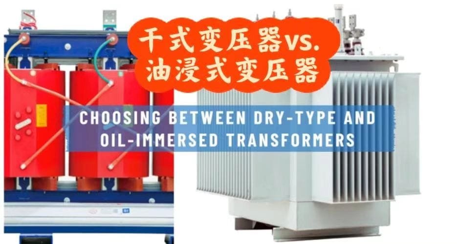
What Is the Difference Between Dry-Type and Oil-Immersed Winding Insulation?
Selecting between dry-type and oil-immersed winding insulation is one of the most critical decisions in transformer specification. The pain point for utilities, EPC contractors, and industrial users is that this choice is often reduced to fire risk or installation location, while ignoring deeper differences in insulation behavior, cooling efficiency, aging mechanisms, voltage capability, and lifecycle cost. The consequence of choosing the wrong insulation system can be overheating, premature insulation failure, regulatory non-compliance, or excessive long-term operating expense. The solution is a clear understanding of how dry-type and oil-immersed winding insulation fundamentally differ in structure, function, and performance.
The key difference between dry-type and oil-immersed winding insulation is that dry-type transformers rely entirely on solid insulation and air for dielectric and thermal performance, while oil-immersed transformers use a composite paper–oil insulation system where insulating oil provides both high dielectric strength and highly effective cooling.
This difference drives transformer size, voltage rating, efficiency, safety profile, and expected service life.
Understanding insulation type is not a detail—it defines the transformer’s operational identity.
Oil-immersed winding insulation systems provide higher dielectric strength and superior cooling compared to dry-type insulation systems.True
The oil–paper composite system fills microscopic voids, suppresses partial discharge, and transfers heat more efficiently than air.
Dry-type winding insulation significantly reduces fire and environmental risks in indoor and urban installations.True
By eliminating liquid insulation, dry-type transformers avoid oil leakage and greatly limit fire propagation.
Fundamental Insulation Philosophy
The difference begins with insulation philosophy.
Dry-type insulation:
- Uses only solid insulating materials
- Relies on air or forced air for cooling
- Eliminates liquid dielectric media
Oil-immersed insulation:
- Uses a composite insulation system
- Combines solid cellulose insulation with liquid oil
- Integrates insulation and cooling into one system
This philosophical difference determines performance limits.
Insulation Materials Used
The materials used in each system are fundamentally different.
Dry-type winding insulation commonly uses:
- Epoxy resin (cast resin systems)
- Polyester or epoxy varnish
- Aramid paper (Nomex®)
- Fiberglass reinforcement
Oil-immersed winding insulation commonly uses:
- Cellulose paper wrapping conductors
- Pressboard barriers and spacers
- Mineral oil, natural ester, or synthetic ester fluids
Each material set responds differently to heat, moisture, and electrical stress.
Dielectric Strength and Voltage Capability
Dielectric performance is one of the most decisive differences.
Oil-immersed insulation:
- Achieves very high dielectric strength
- Oil fills voids and smooths electric fields
- Strongly suppresses partial discharge
Dry-type insulation:
- Relies solely on solid dielectric strength
- More sensitive to manufacturing voids
- Lower maximum voltage ratings
This is why high-voltage and extra-high-voltage transformers are almost always oil-immersed.
Thermal Performance and Cooling Efficiency
Cooling is inseparable from insulation performance.
Oil-immersed insulation:
- Uses oil as an excellent heat transfer medium
- Circulates heat to radiators efficiently
- Supports higher continuous and emergency loading
Dry-type insulation:
- Relies on air cooling
- Lower thermal conductivity
- Higher winding temperature rise
| Aspect | Dry-Type Insulation | Oil-Immersed Insulation |
|---|---|---|
| Cooling medium | Air | Oil |
| Heat dissipation | Moderate | Excellent |
| Power density | Lower | Higher |
Insulation Aging Mechanisms
Aging behavior differs significantly.
Dry-type insulation aging is driven mainly by:
- Thermal stress
- Resin embrittlement
- Surface contamination
Oil-immersed insulation aging involves:
- Thermal aging of cellulose
- Oil oxidation
- Moisture interaction
With proper oil maintenance, oil-immersed insulation generally ages more slowly.
Partial Discharge Behavior
Partial discharge (PD) tolerance is a major distinction.
Oil-immersed insulation:
- Oil suppresses PD effectively
- Higher PD inception voltage
- Slower PD-related degradation
Dry-type insulation:
- More sensitive to PD
- Voids in resin can initiate PD
- PD control depends heavily on manufacturing quality
PD resistance strongly influences long-term reliability.
Fire Safety and Environmental Risk
Fire and environmental considerations often drive insulation choice.
Dry-type insulation:
- No flammable liquid
- Self-extinguishing resin options
- Preferred for indoor, urban, and public buildings
Oil-immersed insulation:
- Contains flammable liquid
- Requires fire protection and containment
- Fire risk reduced by ester insulating fluids
Local regulations frequently mandate dry-type units indoors.
Moisture Sensitivity
Moisture affects the two systems differently.
Oil-immersed insulation:
- Cellulose absorbs moisture
- Oil moisture content is critical
- Requires sealed tanks and drying processes
Dry-type insulation:
- Resin is moisture-resistant
- Surface pollution still matters
- Better suited for humid indoor environments
Mechanical Strength and Short-Circuit Withstand
Mechanical performance under fault conditions also differs.
Oil-immersed insulation:
- Pressboard provides strong structural support
- Oil cushions mechanical shock
- Excellent short-circuit withstand capability
Dry-type insulation:
- Resin encapsulation provides rigidity
- Higher brittleness risk with aging
- Conservative mechanical design required
Maintenance Philosophy
Maintenance requirements reflect insulation system complexity.
Dry-type transformers:
- Minimal routine maintenance
- Periodic inspection and cleaning
- No oil sampling
Oil-immersed transformers:
- Regular oil testing (DGA, moisture)
- Breather and sealing maintenance
- More advanced asset management
Maintenance capability influences total cost of ownership.
Monitoring and Diagnostics
Insulation monitoring differs significantly.
Dry-type monitoring focuses on:
- Winding temperature
- Partial discharge
- Visual inspection
Oil-immersed monitoring includes:
- Dissolved gas analysis
- Moisture-in-oil measurement
- Oil dielectric strength testing
Oil systems provide richer diagnostic information.
Size, Weight, and Installation
Insulation choice affects physical design.
Oil-immersed transformers:
- Smaller and lighter for the same rating
- Require oil containment infrastructure
Dry-type transformers:
- Larger and heavier
- Easier indoor installation without containment
Space constraints often influence selection.
Environmental and Sustainability Considerations
Sustainability is increasingly important.
Dry-type insulation:
- No oil spill risk
- Lower immediate environmental hazard
Oil-immersed insulation:
- Longer service life
- Higher efficiency
- Lower losses over lifecycle
Ester oils improve sustainability performance.
Cost Considerations
Cost profiles differ over time.
Dry-type transformers:
- Higher initial cost at large ratings
- Lower maintenance complexity
Oil-immersed transformers:
- Lower cost per kVA
- Higher maintenance and monitoring requirements
Lifecycle cost analysis is essential.
Typical Application Areas
Each insulation system excels in different applications.
Dry-type transformers are preferred for:
- Commercial buildings
- Hospitals and data centers
- Urban substations
- Fire-sensitive locations
Oil-immersed transformers are preferred for:
- Power generation plants
- Transmission and distribution networks
- Heavy industry
- High-voltage applications
Correct application matching is critical.
Standards and Compliance
Both systems are governed by IEC and IEEE standards, but test requirements differ to reflect insulation behavior and risk profile.
Reliability and Service Life
Typical service life expectations:
- Oil-immersed transformers: 30–50 years
- Dry-type transformers: 20–30 years, depending on loading and environment
Insulation aging is the life-limiting factor in both.
Case Insight: Misapplication Consequences
Industry experience shows:
- Dry-type transformers failing prematurely outdoors under heavy load
- Oil-immersed transformers rejected for indoor use due to fire codes
Understanding insulation differences prevents costly mistakes.
Role in Modern and Net-Zero Power Systems
Oil-immersed insulation supports:
- High efficiency
- Large-scale power transfer
Dry-type insulation supports:
- Safe urban electrification
- Distributed energy systems
Both are essential in modern grids.
Why the Difference Matters
The insulation system defines:
- Electrical performance limits
- Safety profile
- Maintenance strategy
- Total lifecycle value
This decision cannot be made on price alone.
How Is Winding Insulation Tested for Quality and Reliability?
Transformer winding insulation is the single most critical determinant of transformer reliability, yet it is also the most vulnerable element throughout the equipment’s entire lifecycle. The pain point for utilities, EPC contractors, and industrial operators is that insulation defects are often invisible at delivery, silent during early operation, and catastrophic when failure finally occurs—leading to outages, fires, environmental damage, and costly asset replacement. Poor insulation quality cannot be corrected after commissioning. The solution is a rigorous, standardized, and multi-layered insulation testing regime that verifies dielectric strength, mechanical integrity, thermal endurance, and long-term reliability before a transformer ever leaves the factory.
Winding insulation is tested for quality and reliability through a combination of routine, type, and special tests—including electrical dielectric tests, partial discharge measurements, thermal performance tests, mechanical integrity checks, and material verification—designed to prove that the insulation can withstand electrical, thermal, mechanical, and environmental stresses over decades of service.
In transformer engineering, testing is not optional quality control; it is the final proof that insulation design assumptions are correct.
The majority of transformer failures are directly or indirectly linked to winding insulation degradation.True
Industry failure statistics consistently show insulation aging, partial discharge, moisture ingress, and thermal overstress as dominant root causes.
Factory insulation testing can detect latent defects that would otherwise lead to premature transformer failure in service.True
High-voltage, impulse, and partial discharge tests intentionally stress insulation beyond normal operating levels to reveal weaknesses before commissioning.
Why Insulation Testing Is So Critical
Transformer insulation must survive:
- Continuous rated voltage for decades
- Repeated thermal cycling
- Short-circuit mechanical forces
- Lightning and switching surges
Any weakness—voids, contamination, improper drying, or incorrect geometry—can trigger irreversible failure.
Testing validates:
- Design adequacy
- Manufacturing quality
- Material integrity
- Compliance with IEC/IEEE standards
Without testing, insulation reliability is an assumption, not a fact.
Categories of Insulation Tests
Transformer winding insulation testing is structured into three main categories.
| Test Category | Purpose | When Applied |
|---|---|---|
| Routine tests | Detect manufacturing defects | Every transformer |
| Type tests | Validate design performance | Design qualification |
| Special tests | Project- or customer-specific verification | As specified |
Each category addresses different failure risks.
Routine Electrical Insulation Tests
Routine tests are mandatory for every transformer and directly target winding insulation integrity.
These tests are designed to:
- Detect gross insulation defects
- Confirm correct manufacturing
- Ensure safe operation at rated voltage
Insulation Resistance (IR) Test
The insulation resistance test measures leakage current through insulation.
Key objectives:
- Detect moisture contamination
- Identify surface pollution
- Verify insulation dryness
IR values are temperature-corrected and compared against acceptance criteria.
Low insulation resistance is often an early warning of insulation problems.
Polarization Index (PI) Test
The PI test evaluates insulation quality over time.
It measures:
- Insulation resistance at 1 minute
- Insulation resistance at 10 minutes
A healthy insulation system shows increasing resistance over time, indicating good dielectric absorption behavior.
Applied Voltage (Dielectric Withstand) Test
This test applies a high AC voltage between windings and ground.
Purpose:
- Prove insulation can withstand overvoltage
- Detect weak points or breakdown paths
The test voltage exceeds normal operating voltage but remains below destructive levels.
Failure during this test indicates unacceptable insulation defects.
Induced Overvoltage Test
The induced voltage test stresses inter-turn insulation.
Characteristics:
- Elevated voltage at increased frequency
- Applied across the winding itself
This test is critical for detecting:
- Turn-to-turn insulation defects
- Layer insulation weaknesses
It directly validates winding insulation construction quality.
Partial Discharge (PD) Measurement
Partial discharge testing is one of the most powerful insulation diagnostic tools.
PD testing detects:
- Microscopic voids
- Gas pockets
- Sharp edges or stress concentration
Even small PD activity can lead to long-term insulation failure.
PD Acceptance Criteria
PD levels are strictly limited by standards.
| Transformer Type | Typical PD Limit |
|---|---|
| Distribution transformer | ≤ 10–20 pC |
| Power transformer | ≤ 5–10 pC |
| High-voltage units | Often ≤ 5 pC |
Low PD levels indicate high-quality insulation manufacturing.
Type Tests for Insulation Reliability
Type tests are performed to validate insulation system design.
They prove that:
- Materials are suitable
- Geometry is correct
- Thermal and electrical margins are sufficient
Lightning Impulse Test
The impulse test simulates lightning strikes.
It applies:
- Very fast, high-voltage impulses
- Severe electrical stress
This test verifies:
- Insulation coordination
- Surge withstand capability
Impulse failures often reveal design-level insulation weaknesses.
Switching Impulse Test
For extra-high-voltage transformers, switching impulse tests simulate system switching events.
These stresses are lower in magnitude but longer in duration than lightning impulses.
The test validates insulation performance under realistic grid disturbances.
Temperature Rise Test
Thermal performance is inseparable from insulation reliability.
The temperature rise test:
- Operates the transformer under load
- Measures winding and oil temperatures
The goal is to verify insulation operates within its thermal class limits.
Excessive temperature rise accelerates insulation aging.
Thermal Aging Verification
Design validation includes ensuring:
- Hot-spot temperature limits are respected
- Cooling and insulation work as a system
Thermal margin is essential for long service life.
Mechanical Integrity Tests
Insulation must withstand mechanical forces during faults.
Short-circuit withstand capability is verified through:
- Design calculations
- Sometimes short-circuit tests
Insulation spacers, pressboard, and resin structures must maintain geometry under stress.
Material-Level Insulation Testing
Before winding construction, insulation materials themselves are tested.
Typical material tests include:
- Dielectric strength
- Thermal endurance
- Moisture absorption
- Mechanical strength
Material traceability ensures consistency.
Oil-Paper Insulation Quality Tests
For oil-immersed transformers, insulation testing includes oil analysis.
Key oil tests:
- Dielectric breakdown voltage
- Moisture content
- Dissipation factor (tan δ)
Oil quality directly affects winding insulation performance.
Dry-Type Insulation Tests
Dry-type insulation systems require specialized testing.
These include:
- Resin curing quality checks
- Void detection
- Surface tracking resistance tests
Because air replaces oil, manufacturing precision is critical.
Special Tests for High-Reliability Applications
Critical infrastructure often requires additional tests.
Examples:
- Frequency response analysis (FRA)
- Very low frequency (VLF) testing
- Long-duration PD monitoring
These tests provide deeper insight into insulation condition.
Factory Acceptance Testing (FAT)
All insulation tests are performed during FAT.
Customers often witness:
- Applied voltage tests
- PD measurements
- Impulse tests
FAT provides transparency and confidence.
Standards Governing Insulation Testing
Insulation testing is defined by international standards.
Key standards include:
- IEC 60076 series
- IEEE C57 series
These standards define:
- Test methods
- Acceptance criteria
- Safety margins
Compliance ensures global reliability.
Documentation and Traceability
Test results are fully documented.
Records include:
- Test voltages
- Measured values
- Environmental conditions
These records support future diagnostics and warranty claims.
Field Tests After Installation
Some insulation tests are repeated after installation.
These include:
- Insulation resistance
- Ratio tests
- PD measurements (when required)
They confirm insulation integrity after transport and installation.
Relationship Between Testing and Service Life
Well-tested insulation correlates strongly with:
- Longer service life
- Lower failure rates
- Reduced maintenance cost
Testing does not eliminate aging—but it ensures aging starts from a healthy baseline.
Common Insulation Defects Detected by Testing
Factory tests frequently reveal:
- Moisture ingress
- Improper drying
- Manufacturing voids
- Sharp edges causing stress concentration
Early detection prevents costly failures.
Case Insight: Hidden Defect Prevention
Industry case studies show:
- PD detected at factory would have caused failure within 2–3 years in service
- Insulation resistance anomalies prevented commissioning of defective units
Testing saves assets before they become liabilities.
Why Testing Must Be Comprehensive
No single test can guarantee insulation reliability.
Only a combined electrical, thermal, mechanical, and material testing approach provides confidence.
Skipping tests increases risk exponentially.
Role of Modern Digital Testing Technologies
Advanced testing now includes:
- Online PD analysis
- Digital impulse waveform evaluation
- Data-driven acceptance trends
These technologies further improve reliability.
Sustainability and Testing
Reliable insulation testing:
- Extends transformer life
- Reduces replacement frequency
- Minimizes environmental impact
Quality testing supports sustainable power systems.
Conclusion
Transformer windings are insulated using carefully selected solid, liquid, or composite insulation systems designed to withstand electrical, thermal, and mechanical stresses throughout the transformer’s lifespan. Whether through paper and oil systems in oil-immersed transformers or resin and air-based insulation in dry-type units, proper winding insulation is essential for preventing failures, ensuring safe operation, and maintaining long-term performance in modern power systems.
FAQ
Q1: How are transformer windings insulated?
Transformer windings are insulated using a layered insulation system that prevents electrical contact between turns, between windings, and between windings and the core. This system combines solid insulation materials with liquid or air-based insulation, depending on transformer type.
The insulation must withstand electrical stress, mechanical forces, and high operating temperatures over decades of service, making it one of the most critical aspects of transformer design.
Q2: What materials are commonly used for winding insulation?
Common transformer winding insulation materials include:
Enamel-coated copper or aluminum conductors
Cellulose-based insulation paper
Pressboard and molded insulation components
Epoxy resin or varnish (dry type transformers)
Transformer oil or ester fluids (oil-immersed transformers)
These materials are selected for high dielectric strength, thermal endurance, and long-term reliability.
Q3: How does insulation work in oil-immersed transformers?
In oil-immersed transformers, windings are wrapped with insulation paper and immersed in insulating oil. The oil serves two purposes:
Enhances dielectric strength by filling air gaps
Removes heat generated by the windings
Paper-oil insulation systems are highly reliable and have been used in power transformers for more than a century.
Q4: How are windings insulated in dry type transformers?
Dry type transformers use solid insulation systems without oil, most commonly:
Cast resin insulation, where windings are fully encapsulated in epoxy resin
Vacuum pressure impregnation (VPI), where windings are impregnated with insulating varnish
These systems offer excellent fire safety, low maintenance, and resistance to moisture and environmental contamination.
Q5: What is insulation class and why is it important?
Insulation class defines the maximum permissible operating temperature of the insulation system. Common classes include:
Class A (105°C)
Class B (130°C)
Class F (155°C)
Class H (180°C)
Higher insulation classes allow higher operating temperatures, better overload capability, and longer transformer life when properly managed.
Q6: How is insulation arranged between high-voltage and low-voltage windings?
Insulation between windings is carefully engineered using:
Multiple insulation layers
Radial and axial insulation barriers
Oil ducts or air channels for cooling
Reinforced insulation at high-stress regions
This ensures uniform electric field distribution and prevents partial discharge and insulation breakdown.
Q7: How is transformer winding insulation protected against aging?
Insulation aging is mainly caused by heat, moisture, oxygen, and electrical stress. Protection methods include:
Controlled operating temperatures
Sealed transformer tanks or nitrogen blankets
Moisture-resistant insulation materials
Regular condition monitoring and maintenance
Proper protection can extend transformer life to 30–40 years or more.
Q8: How is winding insulation tested?
Transformer winding insulation is tested during manufacturing and commissioning through:
Insulation resistance tests
Dielectric withstand tests
Partial discharge measurements
Oil dielectric strength tests (for oil-filled units)
These tests confirm insulation integrity and compliance with IEC and IEEE standards.
References
IEC 60076 – Power Transformers
https://webstore.iec.ch/publication/602
IEC 60076-3 – Insulation Levels and Dielectric Tests
https://webstore.iec.ch
IEEE C57 Series – Transformer Insulation Standards
https://standards.ieee.org
Schneider Electric – Dry Type Transformer Insulation
https://www.se.com
Electrical Engineering Portal – Transformer Insulation Explained
https://electrical-engineering-portal.com
CIGRE – Transformer Insulation Aging and Performance
https://www.cigre.org
NEMA – Transformer Insulation Classes Guide
https://www.nema.org