Oil-immersed transformers are widely used in power systems due to their excellent insulation and cooling performance. These transformers are filled with insulating oil that helps dissipate heat and provides electrical insulation between internal components. Depending on design, application, and cooling method, oil-immersed transformers can be classified into various types. Understanding these types is essential for selecting the right transformer for specific electrical infrastructure needs.
What Is an Oil-Immersed Transformer?
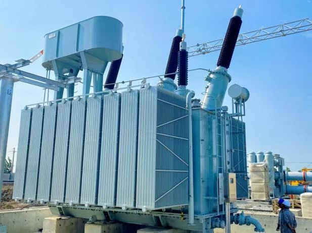
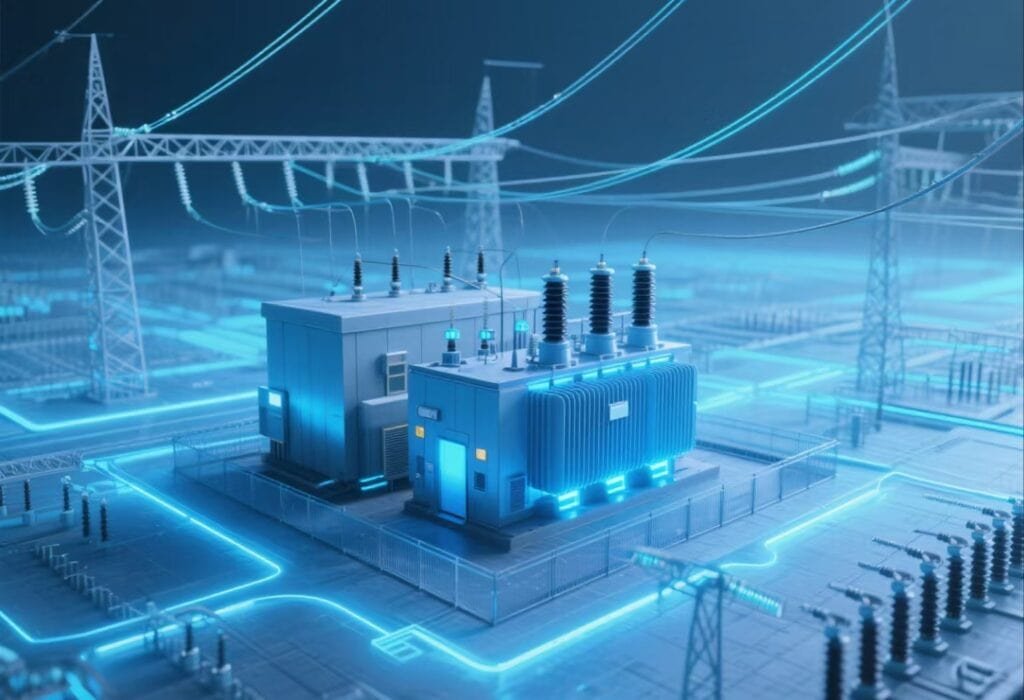
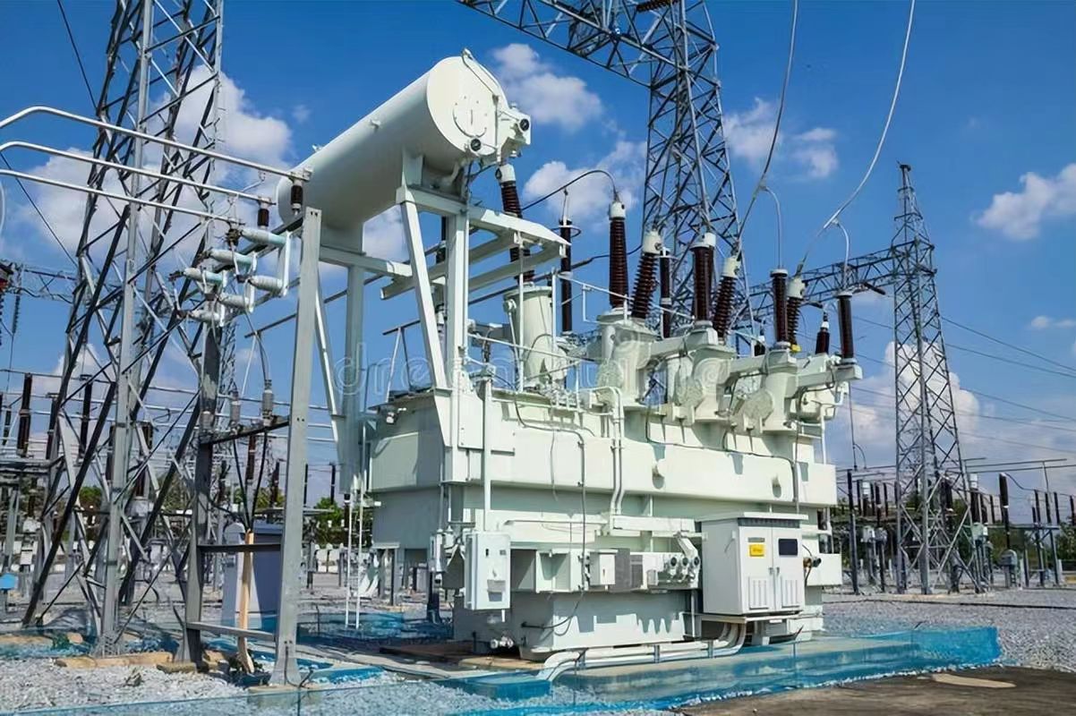
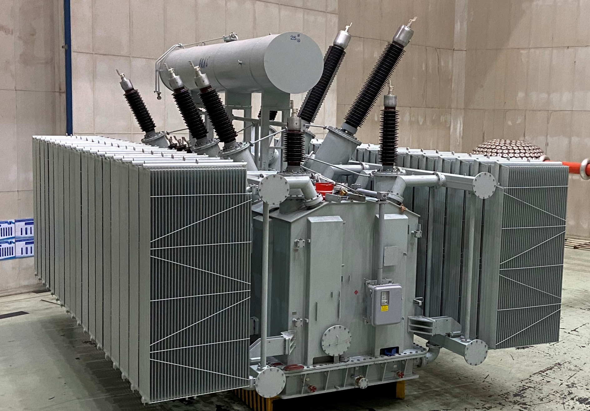
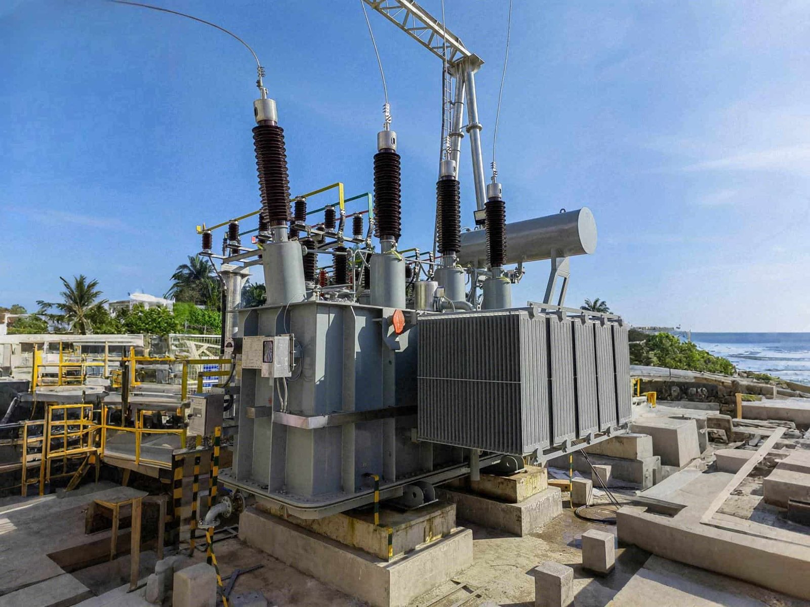
An oil-immersed transformer is the most common and widely used type of power transformer in global electrical networks. In this configuration, the transformer’s core and windings are completely submerged in insulating oil housed within a sealed steel tank. This oil serves as both a dielectric insulator and a coolant, ensuring the equipment operates safely under high voltage and thermal loads. Oil-immersed transformers are used across distribution, transmission, industrial, and renewable applications due to their high reliability, scalability, and efficient thermal performance.
An oil-immersed transformer is a type of electrical transformer in which the core and windings are submerged in insulating oil that serves two main functions: cooling and electrical insulation. The oil circulates naturally or forcibly to dissipate heat, while also enhancing dielectric strength between internal components. This design enables high-voltage operation, long service life, and superior fault tolerance.
These transformers are engineered for both indoor and outdoor installations and can handle voltages from 11 kV up to 765 kV and beyond.
Oil-immersed transformers do not use oil for insulation, only for cooling.False
Oil in an oil-immersed transformer performs both cooling and insulation functions, protecting windings and preventing electrical breakdown.
Core Components of an Oil-Immersed Transformer
| Component | Function |
|---|---|
| Magnetic Core | Directs magnetic flux and minimizes losses |
| Windings (LV & HV) | Conduct electrical energy transformation |
| Insulating Oil | Provides electrical insulation and thermal dissipation |
| Tank and Radiators | Contain oil and transfer heat to air |
| Conservator Tank | Accommodates oil expansion during temperature changes |
| Breather (Silica Gel) | Removes moisture from air entering the conservator |
| Buchholz Relay | Detects gas from faults in oil-immersed systems |
| Pressure Relief Device | Releases excess internal pressure to avoid rupture |
Functions of the Insulating Oil
| Role | Description |
|---|---|
| Electrical Insulation | Prevents arcing and flashover between energized parts |
| Heat Removal | Transfers heat from windings to radiator fins |
| Moisture Barrier | Keeps cellulose insulation dry and stable |
| Arc Suppression | Quenches internal discharges or incipient faults |
Insulating oil enhances both safety and efficiency, making oil immersion essential for high-load environments.
Cooling Methods for Oil-Immersed Transformers
| Cooling Type | Description | Typical Applications |
|---|---|---|
| ONAN | Oil Natural Air Natural – passive circulation | Small to medium transformers |
| ONAF | Oil Natural Air Forced – fans assist cooling | Medium transformers |
| OFAF | Oil Forced Air Forced – oil pumps and fans used | Large power transformers |
| OFWF | Oil Forced Water Forced – water-cooled radiators | Nuclear, HVDC, heavy industry |
Cooling classification is critical to matching a transformer to its operational environment.
Advantages of Oil-Immersed Transformers
| Advantage | Explanation |
|---|---|
| High Voltage Capability | Handles up to 800 kV with reliable insulation |
| Thermal Efficiency | Continuous oil flow regulates temperature |
| Longevity | Life expectancy of 25–40+ years with proper care |
| Robust Construction | Withstands mechanical and electrical stresses |
| Field Maintainable | Oil can be tested, filtered, and restored on-site |
Limitations and Safety Considerations
| Issue | Description |
|---|---|
| Fire Risk | Mineral oil is flammable; requires safety measures |
| Environmental Sensitivity | Oil leaks can pollute soil and groundwater |
| Weight and Size | Large tank and oil volume require transport planning |
| Breather & Seal Aging | Must be maintained to prevent moisture ingress |
Many sites now use natural or synthetic ester oils for improved fire safety and biodegradability.
Use Cases and Applications
| Sector | Example Usage |
|---|---|
| Utilities & Transmission | Substation main step-up and step-down units |
| Heavy Industry | Arc furnace, rolling mill, and petrochemical loads |
| Renewable Energy | Wind and solar inverters, grid-tied substations |
| Railways & Transport | Traction substations, metro infrastructure |
Real-World Case – 132/33 kV Oil-Immersed Transformer
- Deployed at a regional utility substation
- Rating: 40 MVA ONAN/ONAF, mineral oil filled
- Monitored via online DGA, RTDs, and moisture sensor
- Maintained via annual oil testing, vacuum filtration every 4 years
- Performance: 96.2% efficiency, >99.99% reliability over 10 years
Proven durability with zero insulation faults or overheating during high summer peaks
How Are Oil-Immersed Transformers Classified by Cooling Method?
Cooling plays a critical role in transformer performance, particularly in oil-immersed transformers where heat is generated by core and winding losses. The transformer oil not only insulates but also acts as a heat transfer medium, moving heat from inside the transformer to external surfaces where it can be dissipated. Based on how the oil and ambient medium are circulated, oil-immersed transformers are systematically classified by cooling method, which determines their load capacity, thermal efficiency, and design complexity.
Oil-immersed transformers are classified by cooling method using standard codes such as ONAN, ONAF, OFAF, and OFWF. These codes describe how the oil (internal fluid) and the cooling medium (air or water) are circulated—either naturally or forcibly. The classification helps match transformer designs to specific operational loads and environmental conditions.
The correct cooling class is selected during design to ensure safe operating temperatures, efficient load handling, and optimal transformer longevity.
All oil-immersed transformers use the same cooling system.False
Oil-immersed transformers are classified into various cooling types such as ONAN, ONAF, OFAF, and OFWF, each suited to different load and cooling requirements.
IEC/IEEE Cooling Code Format
Each code consists of four letters, split into two pairs:
| Letter | Meaning |
|---|---|
| 1st & 2nd letters | Internal oil circulation: O = Oil, N = Natural, F = Forced |
| 3rd & 4th letters | External cooling medium: A = Air, W = Water, N = Natural, F = Forced |
Example:
ONAN = Oil Natural, Air Natural
OFAF = Oil Forced, Air Forced
Cooling Classifications and Features
| Code | Description | Oil Flow | Cooling Medium Flow | Use Case |
|---|---|---|---|---|
| ONAN | Oil Natural Air Natural | Natural convection | Natural air | <10–25 MVA transformers, low duty cycle |
| ONAF | Oil Natural Air Forced (fans) | Natural | Forced air (fans) | Medium loads, up to ~60 MVA |
| OFAF | Oil Forced Air Forced (oil pumps + fans) | Forced circulation | Forced air (fan + pump) | High-load substations 60–200 MVA |
| OFWF | Oil Forced Water Forced | Forced oil | Water-cooled | Compact stations, high-power industry |
Some transformers support dual ratings, e.g., ONAN/ONAF to increase capacity under forced cooling.
System Design Comparison
| Feature | ONAN | ONAF | OFAF | OFWF |
|---|---|---|---|---|
| Oil Movement | Natural | Natural | Pump-driven | Pump-driven |
| Cooling Medium | Ambient air | Fan-forced air | Fan-forced air | Water-cooled |
| Cooling Efficiency | Low | Moderate | High | Very High |
| Component Complexity | Low | Medium | High | Very High |
| Common Ratings | <20 MVA | 20–60 MVA | 60–200 MVA | >200 MVA |
| Maintenance Needs | Low | Moderate | High | High |
Real-World Example – Dual Cooling Design
- 100 MVA, 220/66 kV transformer designed for ONAN/ONAF
- Base rating (ONAN): 60 MVA
- Boosted rating (ONAF): 100 MVA
- Fans activated during high-load or summer conditions
- Result: improved thermal stability, reduced hot spot aging
Flexibility ensures operational resilience during peak demand
Additional Cooling Enhancements
| Feature | Purpose |
|---|---|
| Radiator Banks | Increase oil surface area for air contact |
| Cooling Fans (ONAF/OFAF) | Accelerate heat dissipation via airflow |
| Oil Circulation Pumps | Ensure even heat distribution, faster cooling |
| Water Heat Exchangers | Used in OFWF for indoor or space-limited sites |
Digital controls often activate fans or pumps based on winding temperature thresholds, improving energy efficiency.
Typical Cooling Curves for Oil-Immersed Transformers
| Cooling Method | Temp Rise Limit (°C) | Relative Efficiency |
|---|---|---|
| ONAN | 55–65 | Baseline |
| ONAF | 45–55 | +20–30% |
| OFAF | 35–45 | +40–50% |
| OFWF | 30–40 | +60%+ |
Lower oil temperatures help maintain insulation integrity and extend transformer service life.
What Are the Main Construction Types of Oil-Immersed Transformers?
Oil-immersed transformers are not one-size-fits-all. They are engineered in a range of construction types to meet varying voltage classes, capacity demands, cooling requirements, spatial constraints, and application-specific performance needs. Each construction form—whether core-type, shell-type, sealed, conservator-equipped, or modular—affects the transformer's cost, performance, serviceability, and space utilization.
The main construction types of oil-immersed transformers include core-type and shell-type based on magnetic circuit structure; sealed and conservator-type based on oil preservation system; single-phase and three-phase based on phase configuration. These variations are designed to optimize insulation, cooling, mechanical strength, and application compatibility across different voltage and power ratings.
Understanding these types helps in selecting the most suitable transformer for technical, operational, and environmental conditions.
All oil-immersed transformers have the same internal structure.False
Oil-immersed transformers vary in magnetic design, oil preservation systems, and phase construction based on application needs and design philosophy.
Classification by Magnetic Core Design
| Type | Description | Use Case |
|---|---|---|
| Core-Type | Windings surround vertical limbs of laminated core | High-voltage power transformers, efficient cooling |
| Shell-Type | Windings enclosed within core limbs, magnetic flux through outer shell | Short-circuit intensive or traction duty transformers |
| Comparison | Core-Type | Shell-Type |
|---|---|---|
| Cooling | Easier oil flow | Moderate oil circulation |
| Structural Rigidity | Moderate | Excellent mechanical support |
| Leakage Reactance | Lower | Higher (good for some industries) |
| Applications | Grid, utility, renewables | Furnace, rail, marine, compact substations |
Core-type dominates in power transmission and large substations, while shell-type excels in industrial or mobile environments.
Classification by Oil Preservation System
| Type | Key Feature | Best Suited For |
|---|---|---|
| Conservator-Type | Equipped with an overhead tank for oil expansion and a breather system | Standard outdoor installations, >5 MVA |
| Sealed-Type | Completely sealed tank, uses nitrogen cushioning or bladder | Low-maintenance environments, <5 MVA, indoor use |
| Feature | Conservator-Type | Sealed-Type |
|---|---|---|
| Oil-Air Contact | Yes (via breather) | No direct contact |
| Moisture Ingress Risk | Higher (if poorly maintained) | Minimal if seals remain intact |
| Maintenance Need | Moderate (breather, oil level) | Low |
| Lifetime Expectancy | Long with care | Fixed with limited serviceability |
Conservator types dominate medium-to-large grid installations, while sealed units are found in urban networks, solar farms, and prefabricated substations.
Classification by Phase Configuration
| Type | Description | Application Scope |
|---|---|---|
| Single-Phase | One core and winding set per unit | Rural feeders, traction systems, modular substations |
| Three-Phase | Three windings around shared or three-legged core | Urban grids, transmission, distribution transformers |
| Comparison Factor | Single-Phase | Three-Phase |
|---|---|---|
| Cost per MVA | Higher | Lower (due to shared components) |
| Transportability | Easier | Complex logistics |
| Flexibility | Modular, easier redundancy | More efficient in balanced systems |
| Installation | Requires parallel setup | One unit installation |
Single-phase units are preferred for railways, backup, or staged systems, while three-phase is the global standard for most utility and industrial installations.
Additional Specialized Designs
| Construction Variant | Application/Feature |
|---|---|
| Hermetically Sealed Tank | Prevents all external contact, ideal for corrosive or flood-prone areas |
| Compact Substation Transformers | Space-constrained or mobile substations (mining, metro) |
| Cast Coil-Oil Hybrid Designs | Combine solid + oil insulation for indoor/outdoor use |
| Mobile Skid-Mounted Units | Temporary grids, emergency deployments |
These designs support evolving needs such as decentralized energy, modular renewables, and disaster recovery grids.
Real-World Case Example
- Utility: 220/66 kV substation for renewable integration
- Specification: 100 MVA, three-phase, core-type, conservator oil-immersed transformer
- Chosen for: efficient cooling, easy oil maintenance, predictable DGA profile
- Installed features: sealed conservator with bladder, smart breather, online sensors
- Outcome: 99.97% uptime over 6 years, zero dielectric events
What Are the Applications of Hermetically Sealed vs. Conservator-Type Transformers?
Oil-immersed transformers are manufactured in two main designs for oil preservation: hermetically sealed and conservator-type. While both systems immerse the windings and core in insulating oil, their oil preservation strategies differ—sealed types rely on airtight tanks with no contact between oil and ambient air, while conservator types use an overhead tank with a breather system to accommodate oil expansion. These designs determine not only the transformer's moisture control and maintenance needs, but also their optimal application environments.
Hermetically sealed transformers are best suited for low- to medium-voltage applications in compact, indoor, or environmentally sensitive areas where minimal maintenance is required. Conservator-type transformers are preferred for higher-capacity, outdoor, and high-voltage systems that require robust oil management and long-term serviceability. Each type addresses specific operational, spatial, and climatic constraints.
Choosing the right system ensures reliability, cost efficiency, and safety across diverse energy infrastructures.
Hermetically sealed transformers can be used in all high-voltage outdoor applications.False
Hermetically sealed transformers are typically limited to low- and medium-voltage applications due to oil expansion limitations and design constraints.
Comparison of Design Characteristics
| Feature | Hermetically Sealed | Conservator-Type |
|---|---|---|
| Oil Preservation | Airtight tank with no contact to air | Breather and expansion tank handle air exchange |
| Moisture Resistance | Excellent | Good (depends on breather maintenance) |
| Oil Expansion Accommodation | Flexible tank walls or nitrogen cushion | Conservator + bladder or free oil surface |
| Maintenance Requirement | Very Low | Moderate (breather, oil level checks) |
| Monitoring Options | Limited to basic gauges | Supports DGA, online sensors, Buchholz relays |
| Typical Oil Volume | Smaller (<5,000 liters) | Larger (10,000–100,000+ liters) |
Applications of Hermetically Sealed Transformers
| Sector | Typical Installation Scenarios |
|---|---|
| Urban Power Distribution | Compact substations, pole-mounted transformers in cities |
| Renewable Energy Systems | Rooftop or ground-mounted solar inverters, wind farms |
| Commercial/Institutional | Shopping centers, hospitals, office buildings |
| Mobile & Prefabricated Units | Container substations, underground vaults |
| Coastal/Corrosive Environments | Corrosion-resistant tanks prevent contamination |
Sealed types are favored where space is limited, oil leaks are a concern, or environmental access is restricted.
Applications of Conservator-Type Transformers
| Sector | Typical Installation Scenarios |
|---|---|
| Transmission & Substations | 66–765 kV grid transformers, step-up/down units |
| Heavy Industrial Plants | Steel mills, cement plants, petrochemical complexes |
| Rural Electrification | High-load rural feeder and utility transformer banks |
| Large Renewable Stations | Utility-scale solar or wind grid tie-in substations |
| Railways & Infrastructure | Traction substations requiring continuous heavy duty |
Conservator systems allow larger oil volumes, flexible loading, and long life with easier oil management.
Key Selection Factors by Environment
| Environmental Factor | Preferred Transformer Type | Justification |
|---|---|---|
| Compact Indoor Location | Hermetically Sealed | No oil breathing or maintenance access required |
| Outdoor High Voltage | Conservator-Type | Supports large oil volume and temperature fluctuation |
| Humid Coastal Climate | Hermetically Sealed | Eliminates air exchange and salt-laden humidity risks |
| Extreme Load Variability | Conservator-Type | Oil expansion and DGA detection manage thermal cycles |
| Maintenance-Free Operation | Hermetically Sealed | Lifetime oil condition stability without intervention |
Performance Limits and Constraints
| Specification | Hermetically Sealed | Conservator-Type |
|---|---|---|
| Max Voltage | Up to 36 kV typically | Up to 765 kV+ |
| Max Capacity | Up to ~5 MVA | 5–500+ MVA |
| Temperature Compensation | Via internal pressure flex or gas | Conservator + bladder or free-breathing tank |
| Monitoring Options | Basic (oil temp, level, pressure) | Full diagnostics including DGA, moisture sensors |
For mission-critical and grid-connected units, conservator-type offers greater flexibility and monitoring integration.
Real-World Deployment Example
- Project: Utility-scale wind farm, 132/33 kV substation
- Transformer choice: 40 MVA, oil-immersed, conservator type
- Reason: Required continuous loading, online DGA, and oil level monitoring
- Features: Smart breather, pressure relief, IED-integrated sensors
Smaller solar array in same project used sealed 1.6 MVA transformers near inverters for maintenance-free distributed power.
What Are the Typical Voltage and Capacity Ranges for Each Type of Oil-Immersed Transformer?
Selecting the right oil-immersed transformer depends heavily on understanding the voltage and capacity limits of each construction type. While both hermetically sealed and conservator-type transformers use oil for insulation and cooling, their structural and operational differences define their application boundaries in terms of voltage rating, power capacity, and service duty.
Hermetically sealed oil-immersed transformers typically operate in the range of 6.6–36 kV and 50 kVA to 5 MVA, suitable for compact distribution networks and renewable inverters. Conservator-type transformers serve higher voltage and power ranges—11 kV up to 765 kV and from 2.5 MVA to 1000+ MVA—covering substation, industrial, and transmission-level operations.
Each type has performance sweet spots that guide engineers in choosing the most reliable and economical solution.
Hermetically sealed transformers are commonly used in 220 kV grid substations.False
Hermetically sealed transformers are typically used below 36 kV due to oil expansion limitations and structural constraints. Conservator-type units are preferred above 66 kV.
Typical Voltage and Capacity Range Overview
| Transformer Type | Voltage Range (kV) | Capacity Range (kVA / MVA) | Best Application Scope |
|---|---|---|---|
| Hermetically Sealed | 6.6–36 | 50 kVA to 5 MVA | Distribution, solar, compact indoor |
| Conservator-Type | 11–765 | 2.5 MVA to 1000+ MVA | Substation, industry, transmission grid |
The gap between 5 and 10 MVA may overlap, with design preference driven by environmental constraints, fire safety, and maintenance philosophy.
Detailed Breakdown by Transformer Type
Hermetically Sealed Transformer Ranges
| Voltage Rating | Typical Power Ratings | Use Case Examples |
|---|---|---|
| 6.6 kV | 50–500 kVA | Factory auxiliary supply, pole-mounted units |
| 11 kV | 100 kVA to 2.5 MVA | Distribution substations, solar string inverters |
| 22–33 kV | 250 kVA to 5 MVA | Wind/solar collector stations, compact substations |
| ≤36 kV | Up to 5 MVA | Renewable grid interfaces, rural/urban feeders |
Many utilities prefer sealed units up to 33 kV for reduced maintenance and compact installations.
Conservator-Type Transformer Ranges
| Voltage Rating | Typical Power Ratings | Use Case Examples |
|---|---|---|
| 11 kV | 2.5–6 MVA | Industrial LV networks, utility feeders |
| 33 kV | 4–25 MVA | Distribution substations, critical buildings |
| 66–132 kV | 10–80 MVA | Grid sub-transmission and step-down stations |
| 220–400 kV | 60–500 MVA | High-voltage transmission substations |
| 765 kV | 500–1000+ MVA | Ultra high-voltage corridors, national grids |
Conservator units dominate the transmission and utility power segments, especially above 66 kV.
Transformer Ratings vs. Application Environment
| Application Environment | Recommended Type | Voltage Class | Power Rating Range |
|---|---|---|---|
| Urban Compact Substation | Hermetically Sealed | 11–33 kV | 250–1600 kVA |
| Utility Grid Feeder | Conservator-Type | 33–66 kV | 5–20 MVA |
| Wind or Solar Plant | Both (depends on scale) | 11–66 kV | 1–40 MVA |
| Heavy Industry | Conservator-Type | 33–132 kV | 5–100 MVA |
| Transmission Substation | Conservator-Type | 132–765 kV | 80–1000+ MVA |
Above 36 kV or 5 MVA, sealed transformers become structurally impractical, giving way to conservator-based solutions.
Performance and Design Impacts by Rating
| Rating Factor | Hermetically Sealed | Conservator-Type |
|---|---|---|
| Thermal Stability | Limited due to enclosed volume | High – oil expansion via conservator |
| Monitoring Options | Basic gauges | Supports full DGA and online monitoring |
| Oil Volume | Small (~100–3000 liters) | Large (~3000–100,000+ liters) |
| Service Life | ~15–25 years | ~30–50+ years with maintenance |
Real-World Specification Snapshot
- Site: Industrial wind farm tie-in substation
- LV Collector Transformer: 2.5 MVA, 33/0.6 kV sealed
- HV Grid Transformer: 40 MVA, 132/33 kV conservator-type
- Why: Compact footprint and sealed operation at inverter level; oil management and monitoring required at grid level
Outcome: Balanced investment, efficient monitoring, and site-specific optimization.
How to Choose the Right Type of Oil-Immersed Transformer?
Choosing the correct oil-immersed transformer is a strategic engineering decision that balances technical performance, long-term reliability, space constraints, cooling needs, and safety compliance. With multiple construction types, cooling configurations, and voltage classes available, selection must consider both electrical parameters and site-specific conditions to avoid operational inefficiencies, overheating, or costly replacements.
To choose the right type of oil-immersed transformer, evaluate the voltage level, rated power, installation environment, cooling requirement, maintenance accessibility, insulation system (sealed or conservator), and safety/environmental factors. Match these against transformer construction types such as core/shell, hermetically sealed/conservator-type, and ONAN/ONAF/OFAF designs to ensure efficient, reliable, and site-adapted operation.
The optimal selection ensures cost-effective service life, thermal stability, and system compatibility.
Transformer type selection is only based on voltage rating.False
Transformer selection must also consider application environment, cooling method, safety, maintenance needs, and installation constraints—not just voltage.
Key Factors for Transformer Selection
| Selection Factor | Key Considerations |
|---|---|
| Voltage Class (kV) | LV (<1 kV), MV (1–36 kV), HV (66–220 kV), EHV/UHV (400–765 kV) |
| Power Rating (kVA/MVA) | Load profile, peak demand, redundancy |
| Cooling Needs | ONAN for small; ONAF/OFAF for medium/large transformers |
| Oil Preservation System | Hermetically sealed (low-maintenance); conservator-type (scalable) |
| Installation Location | Indoor vs outdoor; space availability; ventilation |
| Fire & Environmental Safety | Fire point, biodegradability, eco-fluid use |
| Maintenance Access | Routine oil checks vs sealed units |
| Monitoring Requirements | DGA, moisture sensors, temperature, online diagnostics |
| Cost vs Lifecycle Value | Initial cost vs maintenance, losses, reliability |
Transformer Selection Decision Matrix
| Application Environment | Voltage & Power | Recommended Type |
|---|---|---|
| Compact Urban Substation | ≤36 kV, ≤2.5 MVA | Hermetically sealed, ONAN |
| Industrial Load Center | 11–132 kV, 2.5–80 MVA | Conservator-type, ONAN/ONAF |
| Solar/Wind Farm Inverter | 0.6–33 kV, 500 kVA–5 MVA | Hermetically sealed or sealed conservator |
| Grid Substation (HV) | 66–220 kV, 20–200 MVA | Conservator-type, ONAF/OFAF |
| Critical Infrastructure | 33–132 kV, 5–100 MVA | Sealed conservator with smart monitoring |
| Offshore / Hazardous Zones | ≤33 kV, ≤2 MVA | Hermetically sealed, ester-filled |
| Mobile / Modular Stations | 11–66 kV, up to 10 MVA | Skid-mounted, sealed or compact conservator |
Always confirm environmental regulations, utility standards, and site access constraints before finalizing a type.
Matching Cooling Type to Transformer Capacity
| Capacity (MVA) | Recommended Cooling | Configuration Type |
|---|---|---|
| ≤2.5 MVA | ONAN | Sealed or conservator-type |
| 2.5–25 MVA | ONAN/ONAF | Conservator-type with fans |
| 25–100 MVA | ONAF/OFAF | Conservator-type with pumps/fans |
| >100 MVA | OFAF/OFWF | Conservator-type, high-end grid |
Cooling design must match the thermal loading profile and ambient climate.
Real-World Case Example – Renewable Energy Project
- Project: Hybrid wind + solar installation, 80 MW
- LV Transformers: 2 MVA, 33/0.6 kV, hermetically sealed ONAN
- HV Transformers: 40 MVA, 132/33 kV, conservator-type ONAF
- Site conditions: Remote, humid, minimal maintenance access
- Decision factors: fire safety, modular layout, easy monitoring
Outcome: Optimized footprint, cost-effective maintenance, and reliable grid compliance
Summary Table – Type Selection by Design
| Feature | Hermetically Sealed | Conservator-Type |
|---|---|---|
| Voltage Range | 6.6–36 kV | 11–765 kV |
| Power Range | 50 kVA–5 MVA | 2.5–1000+ MVA |
| Maintenance Requirement | Very Low | Moderate |
| Fire-Safe Fluid Compatibility | Excellent (ester-filled) | Available on request |
| Monitoring Options | Limited | Fully compatible with DGA, sensors |
| Application Scope | Urban, renewables, compact | Grid, industrial, substations |
Conclusion
Oil-immersed transformers come in several variants tailored to specific operational needs, environments, and performance requirements. Whether it's a sealed distribution transformer for urban use or a high-capacity OFAF unit for substations, each type serves a critical role in modern electrical infrastructure. By understanding their distinctions and appropriate use cases, engineers and operators can make informed decisions to optimize system reliability and efficiency.
FAQ
Q1: What are oil-immersed transformers?
A1: Oil-immersed transformers are electrical transformers where the core and windings are submerged in insulating oil, which serves to cool and insulate internal components. These transformers are widely used in power transmission, distribution, and industrial applications due to their high capacity and efficiency.
Q2: What are the main types of oil-immersed transformers?
A2: Common types include:
Distribution Transformers
Typically ≤2.5 MVA
Step down voltage for local distribution
Used in residential and commercial areas
Power Transformers
2.5 MVA and up to hundreds of MVA
Used in transmission substations and generation stations
Designed for high-voltage and continuous load conditions
Autotransformers
Have a single winding acting as both primary and secondary
Used for large voltage changes in compact design
Common in interconnecting grids or voltage regulation
Three-Phase and Single-Phase Oil Transformers
Based on system requirements and load type
Hermetically Sealed Transformers
Fully sealed tanks, no conservator
Suitable for humid or corrosive environments
With Conservator Tank
Includes an oil expansion tank with a breather to manage oil volume change
Q3: What cooling methods are used in oil-immersed transformers?
A3: Cooling classifications (per IEC/IEEE) include:
ONAN (Oil Natural Air Natural): Natural convection of oil and ambient air
ONAF (Oil Natural Air Forced): Oil circulates naturally; air cooled using fans
OFAF (Oil Forced Air Forced): Pumps and fans used for active cooling
OFWF (Oil Forced Water Forced): Used in high-capacity units; requires water cooling
Cooling type impacts transformer size, capacity, and maintenance needs.
Q4: How are oil-immersed transformers classified based on application?
A4: Based on usage:
Step-up Transformers: In power plants to raise voltage
Step-down Transformers: In substations to lower voltage
Furnace Transformers: For industrial heating processes
Traction Transformers: For railway systems
Each type is designed for specific voltage profiles and load behavior.
Q5: What are the advantages of oil-immersed transformers over dry-type?
A5: Higher voltage and power handling capacity
Superior thermal performance and efficiency
Lower cost for high-capacity units
However, they require oil maintenance, fire safety precautions, and proper containment systems in case of leakage.
References
"Types of Transformers: Oil-Immersed and Dry-Type" – https://www.electrical4u.com/types-of-transformers
"IEEE C57 Transformer Standards" – https://ieeexplore.ieee.org/document/8965623
"Hitachi Energy: Oil-Immersed Transformer Designs" – https://www.hitachienergy.com/transformers/oil-immersed
"ScienceDirect: Classification of Power Transformers" – https://www.sciencedirect.com/oil-transformer-classification
"NREL: Types of Transformers in Grid Systems" – https://www.nrel.gov/docs/types-of-grid-transformers.pdf
"Doble: Performance and Design of Oil-Filled Transformers" – https://www.doble.com/oil-transformer-insight