Power transformers play a crucial role in the transmission and distribution of electrical energy. One of the most important specifications of a transformer is its vector group, which defines the winding connections and the phase displacement between the primary and secondary sides. Understanding transformer vector groups is essential for ensuring system compatibility, parallel operation, and stable power supply. This article explains the concept of transformer vector groups, their classifications, and their practical importance in power systems.
What Is a Vector Group in Transformers?
In transformer engineering, many technical issues—from parallel operation failures to protection relay miscoordination—arise because of misunderstanding vector groups. If two transformers with different vector groups are paralleled, circulating currents and excessive heating can occur, risking severe equipment failure. This is a common pain point for engineers, facility managers, and system operators. The solution lies in mastering the meaning of vector groups, their representation, and their impact on network design.
A vector group in transformers indicates the winding connection type (star, delta, or zigzag) and the phase displacement angle between primary and secondary windings using clock notation (e.g., Dyn11). It is a critical parameter for transformer selection, parallel operation, synchronization, and ensuring proper phase alignment within power systems.
Understanding this concept ensures smooth integration, system stability, and compliance with grid standards.
Vector groups only matter for labeling purposes and do not affect transformer operation.False
Vector groups directly affect phase displacement, parallel operation, fault current behavior, and power system stability.
1. Breaking Down Vector Group Notation
Each part of a vector group designation provides specific information:
| Symbol/Number | Description | Example (Dyn11) |
|---|---|---|
| D (uppercase) | Primary winding is connected in Delta | D = Delta |
| Y (uppercase) | Primary winding is connected in Star (Wye) | - |
| Z (uppercase) | Primary winding is Zigzag | - |
| d, y, z (lowercase) | Secondary winding connection (delta, star, zigzag) | y = Star |
| Number (0–11) | Phase displacement in clock-hour notation (each step = 30°) | 11 → 330° lag (or -30°) |
2. Clock Notation and Phase Displacement
The clock-hour system is a visual way to describe the angle difference:
- The primary side is always assumed at 12 o’clock.
- The secondary side is represented by the “hour hand.”
- Each hour = 30° phase shift.
Examples:
- Dyn11: Secondary voltage lags by 30° (11 × 30° = 330°, equivalent to -30°).
- Yd1: Secondary leads by 30° (1 × 30° = +30°).
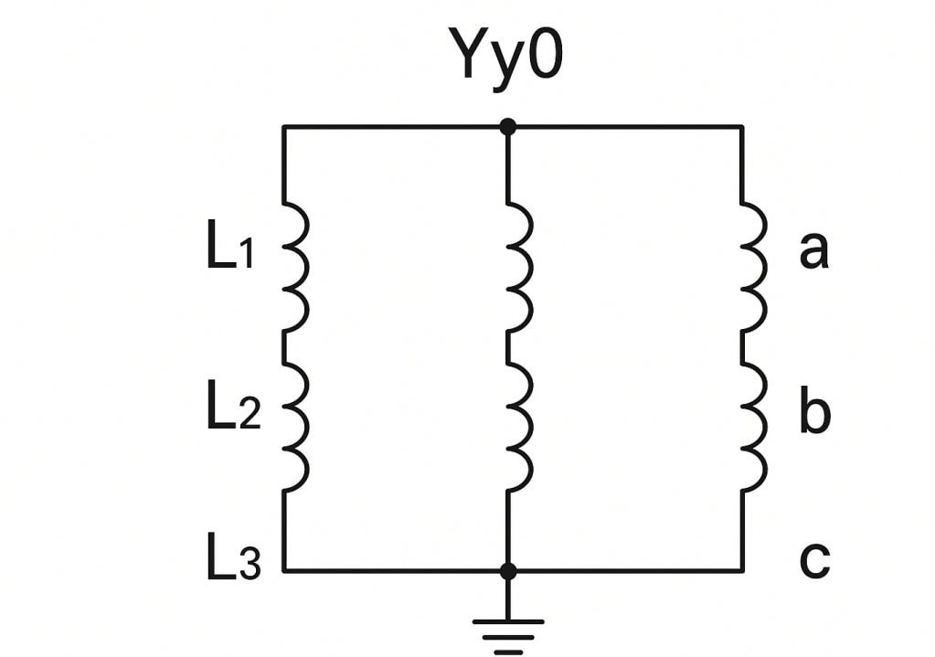
- Yy0: No displacement (0° shift).
This matters because phase displacement affects power flow, fault levels, and synchronization.
3. Why Vector Groups Are Important
Parallel Operation
- Only transformers with the same vector group can be paralleled without circulating currents.
- Example: Dyn11 can parallel with Dyn11, but not with Dyn5.
System Compatibility
- Ensures the transformer’s output matches the utility grid vector group.
- Prevents instability during integration.
Neutral Point Availability
- Star (Y) connections provide a neutral for grounding or supplying single-phase loads.
- Delta (D) connections do not have a neutral unless a special configuration is used.
Fault Current Handling
- Vector groups influence how zero-sequence currents (earth faults) flow in the system.
- Example: Delta connections trap third harmonics, stabilizing the neutral.
Relay and Protection Coordination
- Protection schemes require knowledge of phase displacement.
- Incorrect vector group data can cause false tripping.
4. Common Vector Groups and Their Applications
| Vector Group | Description | Typical Use Case |
|---|---|---|
| Dyn11 | Primary delta, secondary star, -30° shift | Most common distribution transformer; provides neutral |
| Yyn0 | Star/star, no shift | Step-up transformers for generators |
| Yd11 | Primary star, secondary delta, -30° shift | Industrial plants with heavy motor loads |
| Dz0 | Primary delta, secondary zigzag, no shift | Grounding transformers, harmonic suppression |
| Dd0 | Delta/delta, no shift | High current, industrial use with no neutral |
5. Practical Example of Mismatch
If you parallel a Dyn11 and a Dyn5 transformer:
- Both may have delta–star connections.
- But Dyn11 has a -30° shift, while Dyn5 has a +150° shift.
- The result: 330° – 150° = 180° difference → circulating currents, overheating, and possible system collapse.
6. Case Study – Utility Distribution
In European networks, most distribution transformers are Dyn11. Why?
- Provides a neutral for 400/230V loads.
- Filters triplen harmonics (thanks to the delta primary).
- Aligns with system protection settings.
- Ensures compatibility for paralleling at substations.
Why Are Vector Groups Important in Power Systems?
One of the most common sources of power system instability arises when transformers with incompatible vector groups are connected in the same grid or operated in parallel. This mismatch can cause circulating currents, overheating, protective relay miscoordination, and even catastrophic equipment failure. Since transformers are the backbone of electrical power distribution, any error in vector group selection directly threatens system reliability, safety, and power quality.
Vector groups are critically important in power systems because they define the transformer winding configuration (delta, star, zigzag) and the phase displacement between primary and secondary voltages, which directly affects parallel operation, fault current paths, harmonic suppression, grounding methods, and protection coordination. Correct vector group selection ensures compatibility, stability, and efficient power flow across interconnected networks.
When engineers understand vector groups, they avoid dangerous mismatches, design more stable networks, and guarantee compliance with international standards.
Transformers with different vector groups can always be paralleled without issues.False
Transformers must have the same vector group to operate in parallel; otherwise, phase displacement differences cause circulating currents and overheating.
1. Parallel Operation of Transformers
Power systems often require multiple transformers to run in parallel for load sharing and redundancy. Vector groups determine the phase shift between windings:
- If the phase displacement differs, even by 30°, transformers cannot share loads properly.
- Example: Dyn11 and Dyn5 cannot operate together because they differ by 180°.
Key Rule: Only transformers with the same vector group can be paralleled safely.
2. Grounding and Neutral Availability
Vector groups decide whether a transformer provides a neutral point:
- Star (Y) connections → neutral available for single-phase loads.
- Delta (D) → no neutral, but can stabilize third harmonics.
- Zigzag (Z) → commonly used as grounding transformers.
Thus, system designers must pick vector groups that match load and protection requirements.
3. Fault Current Behavior
Vector groups influence how transformers respond to earth faults and unbalanced loads:
- A delta primary traps zero-sequence currents, protecting upstream systems.
- A star secondary allows grounding and controlled fault current paths.
This is critical for designing earth fault relays and protection coordination.
4. Harmonic Suppression and Power Quality
Harmonics—particularly third harmonics (triplen harmonics)—can destabilize systems:
- Delta windings circulate and suppress triplen harmonics internally.
- Without proper vector group design, harmonics could pollute the grid, causing overheating or malfunctions in sensitive equipment.
Thus, vector groups contribute to cleaner power quality.
5. Compatibility with Grid Standards
Utilities and industries follow standard vector groups for network uniformity:
- In Europe, Dyn11 is the most common distribution transformer group.
- In some generator step-up applications, Yy0 or Yd11 are standard.
Compliance prevents interoperability issues when expanding networks.
6. Case Study – Substation Expansion
Imagine a utility expanding a substation with an additional transformer:
- Existing units are Dyn11.
- A new transformer ordered as Dyn5 is mistakenly delivered.
- When paralleled, phase displacement mismatch leads to overheating and tripping.
- Result: supply interruption and financial loss.
Correct vector group identification would have avoided this issue.
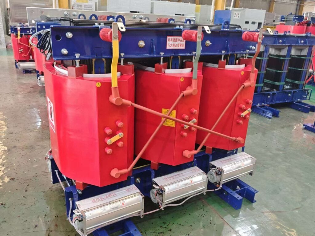
What Are the Types of Transformer Connections (Star, Delta, Zig-Zag) and Their Applications?
![]()
In designing and applying transformers, the way the windings are connected—star (Y), delta (Δ), or zig-zag (Z)—directly affects system voltage, neutral availability, fault current behavior, harmonic suppression, and suitability for specific loads. Choosing the wrong connection can lead to unbalanced loads, improper fault protection, or inefficiencies in power delivery, while selecting the right one ensures stability, safety, and efficiency in distribution and industrial systems.
The three main transformer connections are Star (Y), Delta (Δ), and Zig-Zag (Z). Star provides a neutral point for grounding and is common in distribution; Delta is robust, supports heavy loads, and suppresses triplen harmonics; Zig-Zag is specialized, offering neutral formation and harmonic control in grounding transformers. Each has distinct advantages, limitations, and application areas.
Engineers and operators must understand these connections to ensure compatibility with system requirements, prevent parallel operation issues, and comply with power utility standards.
Delta connection cannot provide a neutral point for grounding.True
Delta windings form a closed loop with no natural neutral point. However, a neutral can be derived through a zig-zag or grounding transformer if required.
1. Star (Y) Connection
- Description: One end of each winding is joined at a common point (neutral), while the other ends connect to the line conductors.
Advantages:
- Provides a neutral for single-phase loads.
- Phase voltage is √3 times lower than line voltage, requiring less insulation.
- Suitable for long-distance transmission where line-to-ground faults must be managed.
Disadvantages:
- Neutral must be grounded properly to avoid overvoltages.
- Unbalanced loads can cause voltage distortion.
Applications:
- Distribution transformers (commonly Dyn11).
- Transmission systems needing neutral grounding.
2. Delta (Δ) Connection
- Description: Windings are connected end-to-end in a closed loop, forming a triangular circuit without a neutral.
Advantages:
- Handles heavy, unbalanced, and nonlinear loads.
- Suppresses third harmonics by circulating them inside the delta loop.
- Provides a path for transformer to continue operating even if one winding fails (open-delta operation).
Disadvantages:
- No natural neutral point (requires auxiliary means for grounding).
- Line voltage = phase voltage, so insulation requirements are higher.
Applications:
- Industrial power systems with large motor loads.
- Step-up transformers at power plants (e.g., Δ-Y).
3. Zig-Zag (Z) Connection
- Description: Each phase winding is split into two halves, wound in opposite directions, and interconnected so that vectorially they balance.
Advantages:
- Provides a stable neutral point without requiring a star connection.
- Excellent suppression of triplen harmonics.
- Balances unbalanced loads effectively.
Disadvantages:
- More complex and costly to manufacture.
- Rarely used except in specialized applications.
Applications:
- Grounding transformers.
- Systems requiring neutral formation in delta-connected networks.
- Harmonic control in sensitive loads like data centers.
Comparison Table of Transformer Connections
| Connection | Neutral Availability | Harmonic Handling | Typical Use Case | Main Advantage | Main Limitation |
|---|---|---|---|---|---|
| Star (Y) | Yes | Moderate (requires grounding) | Distribution & transmission | Neutral available, reduced insulation | Sensitive to unbalance |
| Delta (Δ) | No | Excellent (circulates triplen harmonics) | Industrial loads, step-up transformers | Handles heavy loads, fault tolerance | No neutral, higher insulation |
| Zig-Zag (Z) | Yes (artificial neutral) | Excellent | Grounding, unbalanced load systems | Harmonic suppression, neutral formation | Complex, expensive |
What Is Phase Displacement and Clock Notation in Transformers and How Are They Explained?
In three-phase transformers, phase displacement refers to the angular difference in time (measured in degrees) between the primary and secondary line voltages, caused by the way the windings are connected (star, delta, or zig-zag). To standardize and simplify communication of these angular shifts, the IEC introduced “clock notation,” where the primary winding is fixed at 12 o’clock and the secondary winding is expressed as the corresponding clock-hour position, representing multiples of 30°. Without proper identification of phase displacement, transformers cannot be paralleled safely, as mismatched vector groups cause circulating currents and equipment damage.
Clock notation expresses transformer vector groups, such as Dyn11 or Yd1, where “D” or “Y” indicates the primary connection, “n” the presence of a neutral, and the number represents the phase displacement in clock-hour multiples of 30°. For example, Dyn11 means a delta primary, star secondary with neutral, and secondary voltage lagging by 330° (or leading by 30°).
Understanding this notation is critical for power system engineers to select, install, and parallel transformers correctly.
Clock notation represents the actual timekeeping function of the transformer.False
Clock notation has nothing to do with timekeeping. It is a symbolic method to express the phase displacement between primary and secondary voltages.
1. Phase Displacement in Transformers
Phase displacement arises due to the geometric relationship of line voltages in star and delta connections. For example:
- Star-to-Star (Yy0): No displacement (0°).
- Delta-to-Star (Dy11): Secondary lags primary by 30°.
- Star-to-Delta (Yd1): Secondary leads primary by 30°.
Since each clock position equals 30°, there are 12 possible displacements, from 0° to 330°.
2. Clock Notation Explained
The rules of clock notation are:
- The primary line-to-line voltage vector is always positioned at 12 o’clock (0° reference).
- The secondary line-to-line voltage vector is shown at the corresponding “hour” position.
Each “hour” on the clock = 30° phase shift.
- 1 = 30° lead
- 11 = 330° lag
- 6 = 180° shift (inverted)
Examples:
- Yy0: Star-star, no phase shift.
- Dyn11: Delta primary, star secondary, neutral, secondary voltage lags by 330° (practically treated as 30° lead).
- Yd1: Star primary, delta secondary, 30° lead.
3. Practical Importance of Phase Displacement
- Parallel Operation: Transformers must share the same vector group (clock position) to run in parallel without circulating currents.
- System Compatibility: Utilities often standardize on specific groups (e.g., Dyn11 in distribution networks).
- Harmonic Management: Certain phase shifts help cancel harmonics when operating multiple transformers.
- Protection Coordination: Relay settings depend on knowing the exact vector group.
4. Common Vector Groups in Practice
| Vector Group | Connection | Phase Shift | Application |
|---|---|---|---|
| Yy0 | Star-Star | 0° | Rare, laboratory/testing |
| Dyn11 | Delta-Star Neutral | 330° lag (30° lead) | Distribution networks |
| Yd1 | Star-Delta | 30° lead | Step-down transformers |
| Dy1 | Delta-Star | 30° lead | Industrial networks |
| Yz5 | Star-Zig-Zag | 150° lag | Grounding transformers |
What Are the Common Transformer Vector Groups and Their Applications (e.g., Dyn11, Yyn0, Yd11)?

Dyn11 is the most common vector group in distribution transformers, offering a 30° phase displacement that minimizes harmonics and provides a stable neutral. Yyn0 is used in special cases where both windings are star connected with no phase shift, while Yd11 is often used in step-up or step-down applications in industrial or generation systems requiring delta secondaries.
Understanding these groups ensures proper transformer selection, network stability, and system compatibility.
All transformers can be paralleled regardless of vector group.False
Only transformers with identical vector groups (same displacement and connection type) can be safely paralleled. Different groups cause circulating currents and instability.
1. Dyn11 (Delta Primary, Star Secondary with Neutral, 30° Lag)
- Configuration: Primary = Delta, Secondary = Star with neutral
- Clock Position: 11 (330° lag, or effectively 30° lead)
Applications:
- Widely used in distribution networks worldwide
- Provides a neutral point for single-phase loads
- Suppresses triplen harmonics (3rd, 9th, etc.) due to delta winding
- Common in European utilities and medium-voltage networks
Advantages:
- Reduces unbalanced loads
- Easy fault detection and isolation
- Stable grounding
2. Yyn0 (Star Primary, Star Secondary with Neutral, 0° Shift)
- Configuration: Both windings connected in star, neutral available
- Clock Position: 0 (no phase displacement)
Applications:
- Special use in testing labs, instrumentation, or interconnection
- Suitable where phase alignment is critical and no shift is acceptable
- Less common in power distribution due to higher harmonic issues
Advantages:
- Simplified phasor relationship (no displacement)
- Neutral points available on both sides
Limitations:
- Triplen harmonics pass directly between primary and secondary
- Poor handling of unbalanced loads without additional harmonic filters
3. Yd11 (Star Primary, Delta Secondary, 30° Lag)
- Configuration: Primary = Star (neutral not always used), Secondary = Delta
- Clock Position: 11 (330° lag, 30° lead)
Applications:
- Step-down in industrial plants where delta load is required
- Step-up in generation plants where star side connects to HV grid
- Useful in motor-heavy environments
Advantages:
- Delta side prevents triplen harmonic propagation
- Handles large unbalanced loads effectively
- Suited for heavy-duty industrial use
4. Other Common Vector Groups
| Vector Group | Winding Connection | Phase Displacement | Typical Use |
|---|---|---|---|
| Dyn1 | Delta-Star Neutral | +30° lead | Used in some distribution systems |
| Yd1 | Star-Delta | +30° lead | Step-down for industrial applications |
| Dd0 | Delta-Delta | 0° | Used in special cases for balanced loads |
| Yz5 | Star-Zig-Zag | 150° lag | Neutral grounding and harmonic suppression |
| Dz0 | Delta-Zig-Zag | 0° | Harmonic control, grounding transformer |
5. Choosing the Right Vector Group
- Utility Distribution: Dyn11 (standard worldwide)
- Industrial Plants: Yd11 or Dyn1 (for heavy load handling)
- Testing and Instrumentation: Yyn0 (precise phase alignment)
- Harmonic Mitigation: Yz5 or Dz0 (zig-zag configurations)
- Generation Step-Up: Yd11 or Dy1
What Are the Considerations for Parallel Operation and System Integration of Transformers?
When multiple transformers are required to operate in parallel, careful system integration is essential to ensure they share load proportionally, maintain power quality, and avoid circulating currents or instability. Parallel operation is often necessary in substations, industrial plants, and renewable integration projects, where flexibility, redundancy, and scalability are critical. If mismatches occur in vector group, impedance, or ratings, the system may suffer from overheating, unbalanced loads, or even catastrophic faults.
The main considerations for parallel operation include identical vector groups, same polarity, equal voltage ratios, closely matched impedance, compatible kVA ratings, and synchronized phase sequence. Proper integration also requires careful attention to load sharing schemes, protective coordination, and system grounding practices.
Transformers of different vector groups can share load in parallel if their voltage ratio matches.False
Even with matching ratios, different vector groups have phase shifts that cause circulating currents and cannot operate safely in parallel.
1. Matching Vector Groups
The most fundamental requirement is that all transformers in parallel must have the same vector group. Any phase displacement difference (e.g., Dyn11 vs. Dyn1) creates circulating currents that overload windings.
- Example: Two Dyn11 transformers can run in parallel, but a Dyn11 cannot parallel with a Yd1.
- Best practice: Use transformers with identical manufacturer-specified vector groups for reliability.
2. Voltage Ratio Compatibility
The turns ratio (primary-to-secondary voltage) must be the same, or secondary voltages will differ and create continuous circulating currents.
- Tolerances: Within ±0.5% for successful parallel operation.
- Tap changers may be used to correct small differences.
3. Impedance Matching (Percentage Z%)
- Transformers must have similar per-unit impedance to ensure proper load sharing.
- If one transformer has lower impedance, it will take more load, leading to overloading.
- Rule of thumb: Impedance difference should not exceed ±10%.
4. kVA Rating Considerations
Transformers of unequal ratings can be paralleled, but load sharing must be proportional to their ratings if impedances are the same.
- Example: A 5 MVA and 10 MVA transformer in parallel will share load 1:2.
- If impedances differ, sharing becomes distorted.
5. Polarity and Phase Sequence
- Polarity must match; otherwise, short-circuits occur immediately upon connection.
- Phase sequence alignment is crucial when connecting to busbars or grids; mis-sequence leads to destructive faults.
6. System Integration Aspects
- Protective relaying coordination: Relays must account for both transformers’ characteristics.
- Load management: SCADA or load monitoring systems help balance loads effectively.
- Grounding schemes: Star-connected secondaries with neutrals must have compatible grounding to prevent circulating ground currents.
- Harmonic effects: Delta windings can block triplen harmonics, while star-star connections may pass them.
7. Practical Checklist for Parallel Operation
| Parameter | Requirement for Successful Parallel Operation |
|---|---|
| Vector Group | Must be identical (e.g., Dyn11 with Dyn11) |
| Voltage Ratio | Within ±0.5% |
| Polarity | Same |
| Phase Sequence | Same |
| Impedance (Z%) | Within ±10% |
| kVA Rating | Preferably equal; if not, proportional sharing |
| Grounding | Compatible schemes only |
8. Case Example: Utility Substation
In a city substation, two 20 MVA Dyn11 transformers were paralleled to improve reliability. Matching vector group and impedance allowed seamless load sharing. However, during testing, a slight ratio mismatch (0.7%) caused circulating currents, corrected via tap changer adjustment. This demonstrates how even small mismatches can disrupt stable operation.
Conclusion
Vector groups provide essential information about how a transformer’s windings are connected and the phase shift between input and output voltages. Correct selection of the vector group ensures proper system operation, reduces harmonics, and allows safe parallel operation of multiple transformers. By understanding vector group notations and applications, engineers can make informed decisions that improve grid reliability and performance.
FAQ
Q1: What are vector groups in power transformers?
Vector groups classify the winding configurations (star, delta, or zigzag) of transformer primary and secondary sides and their phase displacement. They are essential for ensuring compatibility in parallel operations and for understanding how voltage phases align between windings.
Q2: Why are vector groups important in transformer applications?
They determine the phase shift between primary and secondary voltages, which affects load sharing, system stability, and fault management. Incorrect vector group selection can cause circulating currents, phase mismatch, and operational inefficiencies.
Q3: What are common transformer vector groups?
Common groups include:
Dyn11 (Delta primary, star secondary, 30° lag)
Yyn0 (Star primary and secondary, zero displacement)
Dyn1 (Delta primary, star secondary, -30° lag)
Yd11 (Star primary, delta secondary, 30° lag)
Each group serves specific system needs like grounding, load balancing, or harmonics control.
Q4: How do you read transformer vector group notation?
The first letter represents the high-voltage winding connection (D = Delta, Y = Star, Z = Zigzag). The second letter indicates the low-voltage winding. The number shows the phase displacement in clock notation (e.g., “11” = 30° lead/lag).
Q5: How does vector group choice affect parallel operation?
For transformers to operate in parallel, they must have the same vector group. Mismatched groups can cause circulating currents and voltage imbalance. For example, two Dyn11 transformers can work together, but a Dyn11 and a Dyn1 cannot.
References
IEEE - Transformer Vector Group Standards: https://ieeexplore.ieee.org
IEC 60076 Standard - Power Transformer Vector Groups: https://webstore.iec.ch
NEMA - Transformer Winding Connections: https://www.nema.org
Electrical4U - Transformer Vector Groups Explained: https://www.electrical4u.com
EEP - Vector Groups and Their Applications: https://electrical-engineering-portal.com
All About Circuits - Understanding Vector Groups: https://www.allaboutcircuits.com
Engineering Toolbox - Transformer Connections and Vector Groups: https://www.engineeringtoolbox.com