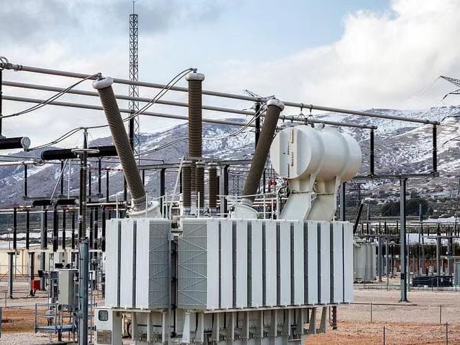
Power transformers are critical in stepping voltage levels up or down in electrical transmission and distribution systems. Their voltage range defines their application—from medium-voltage substations to ultra-high-voltage transmission lines. Understanding these ranges helps determine the right transformer for specific grid levels and operational needs.
What Voltage Levels Are Considered in Power Transformers?
Power transformers are vital components in the transmission and distribution of electricity across national and regional power grids. Because electrical energy must travel long distances from generation sites to end users, transformers are used to step up or step down voltage levels at multiple points in the grid. These voltage levels are standardized across different countries and system designs to ensure efficiency, safety, and grid interoperability.
Power transformers are designed to operate at high and extra-high voltage levels typically ranging from 33 kV up to 765 kV, depending on the location in the power grid. Common primary voltage levels include 400 kV, 220 kV, and 132 kV for transmission; 66 kV and 33 kV for sub-transmission; and 11 kV to 0.4 kV for distribution. The transformer’s design voltage depends on the application—generation, transmission, or distribution.
These voltage classes define the transformer's insulation, bushing, and cooling system requirements.
Power transformers are built to handle high voltage levels ranging from 33 kV to 765 kV depending on their grid application.True
Voltage levels define transformer function—whether stepping up at generation or stepping down near consumers.
All transformers use a single standard voltage level across the grid.False
Transformers are specifically rated for different grid segments, each requiring distinct voltage levels for efficient transmission and delivery.
1. High Voltage (HV), Extra-High Voltage (EHV), and Ultra-High Voltage (UHV)
| Voltage Class | Typical Voltage Range | Transformer Application |
|---|---|---|
| High Voltage (HV) | 66 kV – 220 kV | Substations, primary distribution |
| Extra-High Voltage (EHV) | 220 kV – 400 kV | Transmission networks |
| Ultra-High Voltage (UHV) | 500 kV – 765 kV | Long-distance bulk power transfer |
These voltage levels are used in step-up and interconnection transformers at generation and transmission substations.
2. Common Voltage Levels in National Grids
| Voltage Level | Function | Where Used |
|---|---|---|
| 765 kV | Ultra-high-voltage transmission | National grid backbones (e.g. India, China) |
| 400 kV | Extra-high-voltage bulk transmission | Cross-country lines |
| 220 kV | Regional interconnection and feeders | Utility-to-utility transfer |
| 132 kV | Sub-regional transmission | Grid substations |
| 66 kV / 33 kV | Primary distribution | Step-down to industrial or urban substations |
| 11 kV | Secondary distribution | Final step-down before local supply |
| 0.4 kV / 230 V | Low-voltage service | Residential and commercial supply |
Each stage requires specialized transformers to convert voltage up or down with minimal losses.
3. Voltage Combinations in Typical Power Transformers
| Transformer Type | HV Side | LV Side | Application |
|---|---|---|---|
| Generation Step-Up | 11–25 kV | 132–400 kV | Power plant to grid |
| Transmission Transformer | 400 kV | 220/132 kV | National to regional grid |
| Sub-Transmission Transformer | 132 kV | 66/33 kV | Regional to primary distribution |
| Distribution Transformer | 33/11 kV | 0.4 kV | Substation to end-user |
A single grid may include multiple voltage conversion steps, each requiring a distinct transformer class.
4. Why Voltage Levels Are Important in Transformer Design
| Design Parameter | Why It Depends on Voltage |
|---|---|
| Insulation type and thickness | Higher voltage = more insulation (oil gaps, paper layers) |
| Bushing size and material | Must withstand high voltage and environmental stress |
| Cooling system | Higher voltage = more losses = more heat to dissipate |
| Core and winding dimensions | Scaled based on magnetic and current loading |
The higher the voltage, the more robust the transformer’s mechanical, dielectric, and thermal systems must be.
5. International Standards for Voltage Classification
| Standard Body | Voltage Class Reference |
|---|---|
| IEC 60076 | Defines transformer voltage classes and test levels |
| IEEE C57 | Specifies insulation coordination and HV design |
| ANSI / NEMA | Standardizes LV and MV ratings in North America |
Compliance ensures grid compatibility, safety, and long-term reliability.
6. Real-World Examples by Application
| Project Type | Voltage Levels Used | Transformer Role |
|---|---|---|
| Coal power plant grid tie | 15 kV → 400 kV | Step-up for long-distance transmission |
| Wind farm collector station | 690 V → 33 kV | Boost voltage from turbine to grid |
| Urban substation | 132 kV → 11 kV | Step-down for city distribution |
| Solar farm inverter block | 800 V → 22/33 kV | Pad-mount step-up transformer |
| Industrial factory supply | 33 kV → 0.4 kV | Feeds heavy machinery, HVAC, and lighting |
Summary Table: Voltage Levels in Power Transformers
| Voltage Range | Category | Transformer Role |
|---|---|---|
| 765–500 kV | UHV | National transmission grid |
| 400–220 kV | EHV | Regional bulk power transmission |
| 132–66 kV | HV | Sub-regional distribution and industry |
| 33–11 kV | MV | Primary/secondary distribution |
| 0.4 kV / 230 V | LV | Final delivery to consumers |
How Are Transformers Classified by Voltage?
Transformers are used across all segments of the power grid, from residential service to bulk power transmission. To ensure consistent design, application, and safety, transformers are classified according to their voltage levels, which determine insulation type, application zone, and physical design. Understanding these voltage classes is essential when selecting the right transformer for a particular power system tier.
Transformers are classified by voltage into Low Voltage (LV), Medium Voltage (MV), High Voltage (HV), Extra High Voltage (EHV), and Ultra High Voltage (UHV) categories. Each class corresponds to a specific voltage range and is aligned with grid application zones—from low-voltage delivery to residential loads to ultra-high-voltage transmission lines spanning countries.
These classifications directly influence transformer insulation, bushing design, physical size, and cooling system selection.
Transformers are classified by voltage level into categories such as LV, MV, HV, EHV, and UHV, depending on their application in the power system.True
This classification helps in standardizing design, insulation coordination, and safety practices.
Transformer classification has nothing to do with voltage and only considers power rating.False
Voltage class is a fundamental classification standard, guiding insulation, application, and system compatibility.
1. Transformer Voltage Classification Overview
| Voltage Class | Range | Application Tier |
|---|---|---|
| LV | ≤1 kV | Residential and light commercial |
| MV | >1 kV – ≤35 kV | Local distribution and industry |
| HV | >35 kV – ≤230 kV | Transmission and heavy industrial |
| EHV | >230 kV – ≤400 kV | National transmission lines |
| UHV | >400 kV – up to 765 kV or more | Intercontinental bulk transmission |
These classes are defined by standards such as IEC 60076, IEEE C57, and NEMA TR.
2. Low Voltage (LV) Transformers
| Voltage Range | ≤1 kV |
|---|---|
| Use Cases | Internal building power, electronics, lighting |
| Transformer Type | Dry-type, cast resin, or encapsulated |
| Examples | 400/230 V for residential or UPS isolation |
LV transformers often support electronics, automation, and control panels in safe, dry environments.
3. Medium Voltage (MV) Transformers
| Voltage Range | 1.1 kV – 35 kV |
|---|---|
| Application | Urban substations, factories, commercial zones |
| Designs | Oil-immersed or dry-type |
| Typical Ratings | 100 kVA to 5 MVA |
MV transformers are widely used in secondary distribution, where reliable voltage control is needed.
4. High Voltage (HV) Transformers
| Voltage Range | 36 kV – 230 kV |
|---|---|
| Application | Transmission networks, substations |
| Design Features | High-strength insulation, robust bushings |
| Typical Ratings | 10 MVA – 100 MVA |
HV transformers bridge regional grids and feed primary distribution systems.
5. Extra High Voltage (EHV) Transformers
| Voltage Range | 230 kV – 400 kV |
|---|---|
| Application | Cross-country transmission, inter-regional links |
| Cooling Methods | OFAF, OFWF with advanced monitoring |
| Typical Capacity | 100 MVA – 500 MVA |
These are grid-level transformers found in national transmission substations.
6. Ultra High Voltage (UHV) Transformers
| Voltage Range | 500 kV – 765 kV+ |
|---|---|
| Purpose | Long-distance bulk power movement |
| Countries in Use | China, India, USA, Russia |
| Design Complexity | Multi-winding, modular, advanced insulation |
UHV transformers enable intercontinental power transmission with minimal loss.
7. Voltage Classification vs. Insulation Class
| Parameter | Influenced By Voltage Class |
|---|---|
| Insulation coordination | Higher class = more clearance and insulation |
| Impulse withstand (BIL) | Increases with voltage class |
| Bushing design | UHV/HV bushings are porcelain or composite |
| Cooling demand | Higher voltage → higher thermal losses |
Voltage classification determines how a transformer is built to withstand electrical, mechanical, and thermal stress.
8. Global Examples of Voltage Class Use
| Region/Country | Standard HV/EHV Levels | UHV Projects |
|---|---|---|
| United States (ANSI) | 138 kV, 230 kV, 345 kV, 500 kV | Limited UHV pilot projects |
| European Union (IEC) | 110 kV, 220 kV, 400 kV | EHV networks across Germany, France |
| China | 500 kV, 800 kV, 1000 kV | World’s largest UHV network |
| India | 132 kV, 220 kV, 400 kV, 765 kV | Rapid UHV expansion since 2012 |
UHV usage is increasing to support high-load, long-distance transmission with minimal loss.
Summary Table: Voltage Classification of Transformers
| Class | Voltage Range | Common Applications |
|---|---|---|
| LV | ≤1 kV | Buildings, lighting, electronics |
| MV | 1.1 kV – 35 kV | Commercial, industrial, local substations |
| HV | 36 kV – 230 kV | Transmission substations, heavy industry |
| EHV | 230 kV – 400 kV | Regional/national grid interconnection |
| UHV | 500 kV – 765 kV+ | Cross-country, bulk transmission |
What Is the Typical Voltage Range for Medium, High, and Extra-High Voltage Transformers?
![]()
Power transformers serve as the vital bridge between different voltage levels in the power grid—from local distribution to national transmission. To properly specify or understand transformer roles, it’s essential to know how they’re classified by voltage range. This classification affects transformer insulation design, physical size, application suitability, and safety standards.
The typical voltage ranges for transformers are as follows: Medium Voltage (MV): 1 kV to 35 kV, High Voltage (HV): 36 kV to 230 kV, and Extra-High Voltage (EHV): above 230 kV up to 400 kV. These voltage ranges are aligned with power grid levels—MV for distribution, HV for transmission, and EHV for bulk power transfer across regions.
Each class supports a specific function in the energy delivery chain and determines the transformer's technical construction.
Medium voltage transformers operate between 1 kV and 35 kV, high voltage between 36 kV and 230 kV, and extra-high voltage above 230 kV up to 400 kV.True
These classifications follow IEC and IEEE standards, guiding transformer design and application.
All power transformers operate at the same voltage level regardless of their use.False
Different grid zones require transformers to step voltage up or down according to standardized voltage classes.
1. Medium Voltage (MV) Transformers: 1 kV – 35 kV
| Typical Voltage Range | 1.1 kV – 35 kV |
|---|---|
| Use Cases | Secondary distribution, small substations, industrial plants |
| Common Ratings | 3.3 kV, 6.6 kV, 11 kV, 22 kV, 33 kV |
| Transformer Capacity | 100 kVA – 5 MVA |
| Design Options | Oil-immersed or dry-type |
MV transformers are ideal for linking utility distribution networks to industrial and commercial users.
2. High Voltage (HV) Transformers: 36 kV – 230 kV
| Typical Voltage Range | 36 kV – 230 kV |
|---|---|
| Use Cases | Transmission substations, large-scale industries |
| Common Ratings | 66 kV, 110 kV, 132 kV, 150 kV, 220 kV |
| Transformer Capacity | 10 MVA – 100 MVA |
| Design Characteristics | Higher insulation strength, larger cooling systems |
HV transformers carry electricity between major substations and feed lower-voltage distribution systems.
3. Extra-High Voltage (EHV) Transformers: 230 kV – 400 kV
| Typical Voltage Range | >230 kV up to 400 kV |
|---|---|
| Use Cases | National transmission lines, inter-regional power transfer |
| Common Ratings | 275 kV, 330 kV, 345 kV, 400 kV |
| Transformer Capacity | 100 MVA – 500 MVA+ |
| Design Requirements | Advanced cooling (OFAF/OFWF), large footprint, special bushings |
EHV transformers are critical for efficient long-distance transmission, minimizing I²R losses across national grids.
4. Voltage Class Comparison Table
| Voltage Class | Voltage Range | Typical Applications | Transformer Type |
|---|---|---|---|
| Medium Voltage | 1 kV – 35 kV | Urban/rural distribution, industrial loads | Distribution transformers |
| High Voltage | 36 kV – 230 kV | Regional transmission, heavy industry | Power transformers |
| Extra-High Voltage | >230 kV – 400 kV | Bulk transmission, interconnection points | EHV grid transformers |
5. Real-World Examples
| Application | Voltage Levels | Transformer Role |
|---|---|---|
| City substation | 132 kV → 33 kV | HV transformer for regional distribution |
| Wind farm collector | 33 kV → 132 kV | MV to HV step-up transformer |
| Power plant grid injection | 22 kV → 400 kV | Step-up EHV transformer |
| Industrial power supply | 33 kV → 11 kV or 6.6 kV | MV transformer for process loads |
How Do Voltage Ratings Affect Insulation and Design?
Voltage rating is one of the most critical factors in transformer design. It determines how much electrical stress the transformer components must withstand under both normal and abnormal conditions. As voltage levels increase, the insulation system must be strengthened, the physical clearances must be enlarged, and the overall transformer design becomes more robust and complex. Ignoring this relationship can lead to insulation failure, arcing, overheating, and catastrophic damage.
Voltage ratings directly influence transformer insulation levels, bushing design, internal clearances, dielectric material selection, and winding configuration. Higher voltage classes require thicker insulation, longer creepage distances, more complex winding separation, and stronger dielectric strength to withstand operating voltages and impulse conditions (e.g., lightning or switching surges).
Designing for the right voltage class is essential for both safety and long-term performance.
Voltage ratings directly determine transformer insulation thickness, creepage distance, and dielectric strength requirements.True
Higher voltage transformers need enhanced insulation and wider spacing to prevent flashover and ensure safe operation.
Transformer insulation systems are identical regardless of voltage class.False
Insulation systems must be engineered to withstand the specific voltage and impulse levels the transformer will experience.
1. How Voltage Rating Influences Transformer Insulation Design
| Design Aspect | Effect of Higher Voltage Ratings |
|---|---|
| Insulation thickness | Increases to withstand higher operating and impulse voltages |
| Creepage distance | Extended to avoid surface tracking or flashover |
| Dielectric material type | Higher grades used (oil, paper, resin, Nomex) |
| Bushing size and type | Larger, sometimes capacitive-graded bushings used |
| Clearance inside windings | More spacing required between turns and layers |
The higher the system voltage, the more robust and spatially demanding the insulation system becomes.
2. Typical Insulation Requirements by Voltage Class
| Voltage Class | Rated Voltage (kV) | Basic Impulse Level (BIL) | Design Implication |
|---|---|---|---|
| Low Voltage (LV) | ≤1 kV | N/A | Minimal insulation, often dry-type |
| Medium Voltage (MV) | 3.3–33 kV | 45–170 kV | Paper-oil insulation or cast resin |
| High Voltage (HV) | 66–230 kV | 250–750 kV | Oil-paper insulation, larger bushings |
| Extra-High Voltage (EHV) | 275–400 kV | 900–1550 kV | Graded insulation, impulse-tested extensively |
| Ultra-High Voltage (UHV) | 500–765 kV | 1800–2450 kV | Complex insulation coordination and shielding |
These insulation levels are standardized by IEC 60076-3 and IEEE C57.12.00.
3. Bushing and Terminal Design for High Voltage
| Voltage Rating | Bushing Type | Key Design Elements |
|---|---|---|
| ≤33 kV | Solid porcelain or epoxy | Compact, suitable for indoor/outdoor use |
| 66–220 kV | Oil-filled porcelain | Larger, with capacitive grading to prevent corona |
| 400 kV+ | Condenser bushings | Very large, highly engineered for impulse strength |
Bushings must maintain dielectric integrity and handle both voltage and mechanical stress.
4. Impact on Winding and Core Design
| Component | Higher Voltage Requirement |
|---|---|
| Winding layout | Interleaved/disc or multilayer to manage voltage gradient |
| Insulation between layers | Must withstand full winding-to-ground voltage differential |
| Winding-to-core distance | Larger air gaps to reduce capacitive coupling and heat rise |
| Impulse withstand margin | Enhanced spacing and shielding to survive transient overvoltages |
Without proper layout, localized voltage stress can cause partial discharges or insulation breakdown.
5. Thermal and Structural Design Implications
| Challenge | Design Countermeasure |
|---|---|
| Increased losses at high voltage | Enhanced cooling (ONAF, OFAF, OFWF) |
| High mechanical forces during faults | Reinforced winding supports and clamping |
| Dielectric oil aging | Oil filtration and advanced monitoring systems |
High voltage increases thermal and mechanical design complexity.
6. Case Study: 400 kV Transformer vs 33 kV Transformer
| Design Parameter | 33 kV Unit | 400 kV Unit |
|---|---|---|
| Bushing height | \~600 mm | >3,000 mm |
| Core-to-winding clearance | 20–30 mm | ≥100 mm |
| Insulation paper thickness | \~1 mm | Up to 8–10 mm |
| Total transformer height | \~2 m | >6–7 m |
| BIL | \~170 kV | \~1550 kV |
The 400 kV unit needs 8–10 times more insulation strength and space, making it significantly larger and heavier.
Summary Table: How Voltage Ratings Affect Insulation and Design
| Voltage Level | Insulation Demand | Design Adaptations |
|---|---|---|
| LV (≤1 kV) | Minimal | Compact dry insulation, low air clearance |
| MV (1–35 kV) | Moderate | Paper-oil or epoxy systems, 1–5 mm insulation, small bushings |
| HV (36–230 kV) | High | Oil-paper, 5–8 mm insulation, large porcelain bushings |
| EHV (230–400 kV) | Very High | Impulse-tested insulation, larger creepage distances |
| UHV (500–765 kV+) | Extreme | Multi-layered insulation, capacitive bushings, impulse shielding |
What Standards Govern Voltage Classifications?
When designing or specifying a power transformer, aligning with recognized international or national standards is essential. Voltage classification isn’t just about labeling; it dictates insulation coordination, construction practices, testing protocols, and safety requirements. To ensure interoperability and reliability across grids worldwide, industry standards define voltage ranges, insulation levels, and associated design parameters for transformers at each class.
The main standards that govern voltage classifications in transformers include IEC 60076 (International), IEEE C57 (USA), ANSI C84.1 (USA), and NEMA (North America). These standards define Low Voltage (LV), Medium Voltage (MV), High Voltage (HV), Extra High Voltage (EHV), and Ultra High Voltage (UHV) classes, specifying the corresponding system voltages, insulation requirements, test procedures, and acceptable tolerances.
Using standardized voltage classes ensures safe design, consistent performance, and regulatory compliance worldwide.
Voltage classifications in transformers are governed by international and regional standards such as IEC 60076 and IEEE C57.True
These standards define voltage ranges and associated insulation, design, and testing requirements.
Transformer voltage classification is arbitrary and not defined by any industry standards.False
Voltage classifications are carefully defined by globally recognized standards to ensure safe and consistent transformer operation.
1. IEC 60076 Series (International Electrotechnical Commission)
| Document | Focus Area | Key Voltage Classification Roles |
|---|---|---|
| IEC 60076-1 | General requirements | Defines nominal voltages and system categories |
| IEC 60076-3 | Insulation levels and dielectric tests | Links voltage class with BIL and withstand tests |
| IEC 60076-5 | Short-circuit withstand capacity | Addresses mechanical and electrical stress ratings |
| IEC 60071 | Insulation coordination | Used for overvoltage protection and clearance design |
IEC defines LV as ≤1 kV, MV as >1 kV to 35 kV, HV as >35 kV to 230 kV, and EHV/UHV as >230 kV.
2. IEEE C57 Series (Institute of Electrical and Electronics Engineers)
| Standard | Scope | Voltage Classification Coverage |
|---|---|---|
| IEEE C57.12.00 | General requirements for liquid-filled transformers | Provides HV and EHV definitions and testing |
| IEEE C57.12.01 | Dry-type transformers | MV/LV definitions, insulation classes |
| IEEE C57.91 | Loading guides | Informs thermal and voltage stress considerations |
| IEEE Std 1313.2 | Insulation coordination for HV systems | Harmonizes insulation levels across voltage classes |
IEEE aligns broadly with IEC but uses some region-specific nomenclature, especially in MV and HV demarcation.
3. ANSI C84.1 (American National Standards Institute)
| Defined Class | Nominal Voltage Ranges (US context) | Primary Use |
|---|---|---|
| LV | 120 V – 600 V | Residential and light commercial |
| MV | 2400 V – 69 kV | Distribution and light industry |
| HV | 115 kV – 230 kV | Transmission systems |
| EHV | Above 230 kV | Interstate and bulk transmission |
ANSI focuses on utility and grid-connected voltage levels used in North America.
4. NEMA Standards (National Electrical Manufacturers Association)
| NEMA Standard | Purpose | Voltage Classification Notes |
|---|---|---|
| NEMA TR 1 | Transformers, regulators, reactors | Covers MV and LV design classifications |
| NEMA ST 20 | Dry-type transformers | Lists common voltage configurations |
NEMA complements ANSI and IEEE in defining enclosure ratings, system voltages, and labeling standards.
5. Summary Table: Voltage Classification by Standard
| Voltage Class | IEC | IEEE / ANSI / NEMA |
|---|---|---|
| LV | ≤1 kV | ≤600 V (ANSI), ≤1.2 kV (IEEE/NEMA) |
| MV | >1 kV – 35 kV | 1.2 kV – 69 kV (ANSI), ≤72.5 kV (IEEE) |
| HV | >35 kV – 230 kV | 72.5 kV – 230 kV (IEEE/ANSI) |
| EHV | >230 kV – 400 kV | >230 kV – 345 kV/400 kV (IEEE/ANSI) |
| UHV | >400 kV | 500–765 kV+ (UHV defined more by IEC globally) |
Despite regional differences, standards are often harmonized to allow international equipment compatibility.
6. Why These Standards Matter
| Design Element Affected | Standard Impact |
|---|---|
| Insulation coordination | BIL levels must match standard voltage class |
| Clearances and creepage | Based on standard dielectric strength thresholds |
| Test procedures | Defined per voltage level and transformer type |
| System planning | Utilities match components to standardized voltages |
| Transformer labeling and specs | Standardized for safety and interoperability |
Compliance with these standards ensures that equipment from different manufacturers can operate reliably on the same grid.
7. Real-World Implication: Mismatch vs Compliance
Non-compliant design:
A 132 kV transformer designed using 66 kV insulation criteria will fail standard impulse tests and pose a safety risk.Compliant design:
A transformer meeting IEC 60076 BIL levels for 132 kV (e.g., 550 kV) ensures resilience against overvoltage events.
Design engineers must specify standards upfront to prevent dangerous mismatches or test failures.
Summary Table: Key Standards for Voltage Classification in Transformers
| Standard Body | Document(s) | Covers |
|---|---|---|
| IEC | 60076 series, 60071 | Global voltage classes, insulation, test levels |
| IEEE | C57 series, 1313.2 | North American standards, coordination, dry/oil types |
| ANSI | C84.1 | System nominal voltages (US utilities) |
| NEMA | TR 1, ST 20 | Voltage rating + enclosure standards |
How to Select the Right Voltage Rating for Your Application?
Selecting the correct voltage rating is one of the most critical decisions when designing or procuring a transformer. The wrong voltage rating can result in incompatibility with the grid, overload conditions, high losses, or even insulation failure. Whether you're integrating into a transmission network, supplying an industrial plant, or connecting to a residential load, the transformer voltage must match the application’s system voltage, load behavior, and regulatory standards.
To select the right voltage rating for your application, evaluate the primary and secondary system voltages, grid interface requirements, transformer type (step-up or step-down), load profile, fault level tolerance, insulation class, and future scalability. Match these factors with applicable standards (IEC, IEEE, ANSI) and ensure the selected voltage supports operational efficiency, protection coordination, and safe insulation design.
The goal is not just to connect power—but to deliver it safely, efficiently, and sustainably.
Transformer voltage ratings must match the system's primary and secondary voltages while considering insulation coordination and fault levels.True
Selecting the right voltage ensures compatibility, safety, and reliable operation within the power system.
Transformer voltage ratings can be selected arbitrarily without regard to the connected system.False
Voltage mismatches lead to operational hazards, failed integration, and potential insulation breakdown.
1. Identify Your System Voltage Levels
| Step | Why It Matters |
|---|---|
| Determine the grid supply voltage | This defines the primary (input) side of the transformer |
| Identify your load or equipment voltage | Defines the secondary (output) voltage requirement |
| Check if you need a step-up or step-down unit | Impacts winding and core design |
Always match the voltage to existing grid code or utility standards in your region.
2. Match Voltage Class to Application Type
| Application | Recommended Voltage Classes | Typical Use Case |
|---|---|---|
| Residential neighborhood | 11 kV → 0.4 kV (MV to LV) | Pole or pad-mounted distribution transformer |
| Commercial complex | 33 kV → 0.4 kV or 11 kV → 0.4 kV | Compact substation or indoor dry-type units |
| Industrial plant | 33 kV → 6.6 kV or 11 kV | Process machinery, motors, HVAC |
| Utility substation | 132 kV → 33/11 kV | Feeds multiple distribution zones |
| Solar/wind farm | 690 V → 33 kV or 33 kV → 132 kV | Step-up to medium or high voltage grid |
| Power plant grid tie | 11/22 kV → 220/400 kV | High-capacity generation interconnection |
The application dictates the voltage combination and insulation requirements of the transformer.
3. Review Transformer Types and Their Voltage Ranges
| Transformer Type | Typical Voltage Range | Main Function |
|---|---|---|
| Distribution Transformer | 11 kV / 6.6 kV → 0.4 kV | Final voltage drop for users |
| Power Transformer | 33–400 kV | Interconnection in transmission grid |
| Step-up Transformer | 11–22 kV → 132–400 kV | Boost voltage for efficient transmission |
| Renewable Pad-Mount | 690 V / 800 V → 11–33 kV | Export inverter output to grid |
Each transformer type supports a different voltage range, and must be matched accordingly.
4. Consider Insulation Level and System BIL
| Voltage Class | Required BIL (Basic Impulse Level) | Insulation Impact |
|---|---|---|
| 11 kV | \~95 kV | Light insulation |
| 33 kV | \~170 kV | Medium insulation |
| 132 kV | \~550 kV | High insulation with large creepage |
| 400 kV | \~1425 kV | Very high insulation, capacitive bushings |
A voltage mismatch can cause insulation breakdown under switching or lightning surges.
5. Assess Load Profile and Fault Level Constraints
| Factor | Why It Affects Voltage Rating Selection |
|---|---|
| Short-circuit level | High fault current may require a higher voltage transformer with more insulation |
| Load variability | Requires OLTC with wider voltage range |
| Overload capacity | May affect selection of voltage tap points |
| Future expansion | Design for a higher secondary voltage to support additional loads |
Your transformer must withstand real-world grid conditions, not just nominal operation.
6. Use National and International Standards as Reference
| Standard | Voltage Guidance Provided |
|---|---|
| IEC 60076-1 / 60071 | Nominal voltages, insulation coordination |
| IEEE C57.12 | Voltage ratings and testing protocols |
| ANSI C84.1 | Defines acceptable system voltage ranges |
| Utility codes (e.g., PG\&E, UK DNOs) | Grid-specific voltage service levels |
Compliance ensures safety, legal conformity, and interoperability.
7. Practical Case Study: Industrial Factory Supply
- System Supply Voltage: 33 kV from utility
- Internal Equipment Voltage: 6.6 kV and 0.4 kV
Solution:
- One transformer: 33 kV / 6.6 kV for process loads
- Another transformer: 33 kV / 0.4 kV for utilities and admin building
- Voltage Rating Decision: Based on existing utility grid + plant distribution design
- Benefits: Proper insulation class, optimized tap settings, correct short-circuit level handling
Right voltage selection resulted in high efficiency, minimal loss, and regulatory compliance.
Summary Table: Steps to Select the Right Transformer Voltage Rating
| Step | Key Question | Design Outcome |
|---|---|---|
| 1. Identify system voltages | What are the grid and load voltages? | Primary/secondary ratings |
| 2. Define transformer type | Step-up, step-down, or interconnecting? | Application-specific model |
| 3. Match to voltage class | LV, MV, HV, EHV? | Correct insulation and physical design |
| 4. Consider load and fault conditions | High fault current or sensitive loads? | Impedance and thermal design optimization |
| 5. Verify with standards | IEC, IEEE, ANSI compliance? | Testable, safe, and certified transformer |
| 6. Plan for future needs | Will voltage need to support more load later? | Scalable and future-proof design |
Conclusion
Power transformers typically operate within a wide voltage range—from 33 kV up to 765 kV and beyond, depending on their role in the grid. Medium-voltage transformers (up to 66 kV) are used for distribution, while high-voltage and extra-high-voltage transformers (110 kV to 765 kV) serve long-distance transmission. Choosing the appropriate voltage class ensures electrical safety, system compatibility, and efficiency.
FAQ
Q1: What is the typical voltage range of a power transformer?
A1: Power transformers are generally designed for medium to high voltage applications, operating in the range of 33kV to 765kV or higher. These high voltage levels are required for efficient long-distance power transmission and bulk power distribution in national grids.
Q2: What are common voltage levels used in power transformers?
A2: Standard voltage ratings often include:
33kV
66kV
110kV
132kV
220kV
400kV
500kV to 765kV (for extra high-voltage transmission systems)
These values may vary by country and grid standard.
Q3: Are power transformers used at low voltages?
A3: No. Low-voltage transformers (typically <1kV) are not classified as power transformers. Those are distribution or control transformers. Power transformers are specifically used for medium and high-voltage operations above 33kV.
Q4: How does the voltage rating affect transformer design?
A4: Higher voltage ratings require:
More insulation
Larger physical size
Stronger dielectric strength
Advanced cooling systems
These designs help handle high electric stress and thermal loads in transmission systems.
Q5: Can a power transformer be designed with custom voltage ratings?
A5: Yes. Power transformers can be custom-engineered to match specific primary and secondary voltage requirements, particularly for:
Grid interconnections
Renewable energy plants
Industrial substations
Custom designs ensure optimal performance and grid compatibility.
References
"Voltage Ratings of Power Transformers" – https://www.transformertech.com/voltage-range-power-transformers
"Power Transformer Voltage Classes" – https://www.electrical4u.com/transformer-voltage-levels
"PowerGrid: Guide to Transformer Voltage Ratings" – https://www.powergrid.com/transformer-voltage-guide
"Smart Grid News: Understanding Transmission Voltages" – https://www.smartgridnews.com/power-transformer-voltage-range
"ResearchGate: Transformer Design by Voltage Class" – https://www.researchgate.net/voltage-based-transformer-design
"ScienceDirect: High-Voltage Transformer Standards" – https://www.sciencedirect.com/power-transformer-voltage
"Siemens Energy: Voltage Range of Grid Transformers" – https://www.siemens-energy.com/voltage-capacity-transformers
"Energy Central: Voltage Requirements in Modern Grids" – https://www.energycentral.com/c/ee/power-transformer-voltage-levels