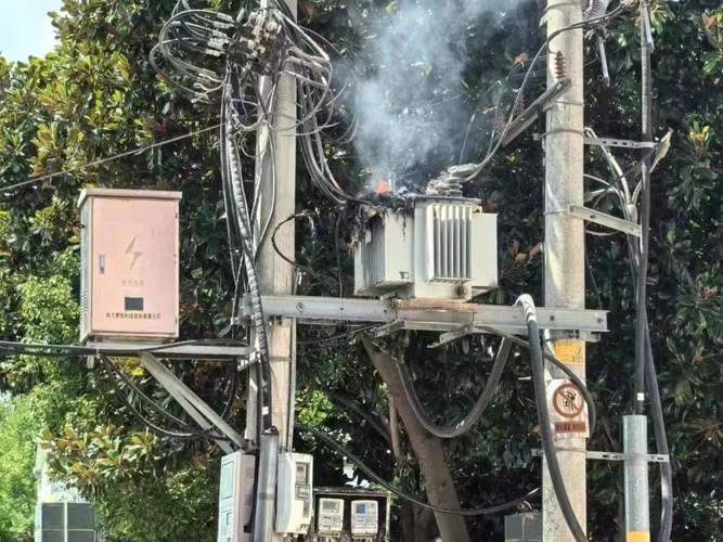
Transformers are critical components in power systems, designed for long-term reliability. However, under electrical, thermal, or mechanical stress, certain parts can overheat, degrade, or burn out, leading to failure. Understanding what actually burns out inside a transformer helps operators, engineers, and technicians identify early warning signs, perform preventive maintenance, and minimize system downtime. This guide explores the internal components most vulnerable to thermal and electrical stress, common causes of burnout, and how to diagnose potential issues before failure occurs.
What Are the Main Components of a Transformer?
Transformers are at the heart of modern power distribution—stepping voltages up or down with remarkable efficiency. But what lies inside these seemingly simple metal boxes? When failure occurs or performance declines, knowing the key internal and external components of a transformer becomes critical. Whether you’re an electrical engineer, utility operator, or industrial maintenance technician, a thorough understanding of transformer components will aid in diagnostics, maintenance, and system optimization. In this article, we’ll dissect the anatomy of a transformer and explain how each part contributes to energy transfer, insulation, safety, and cooling.
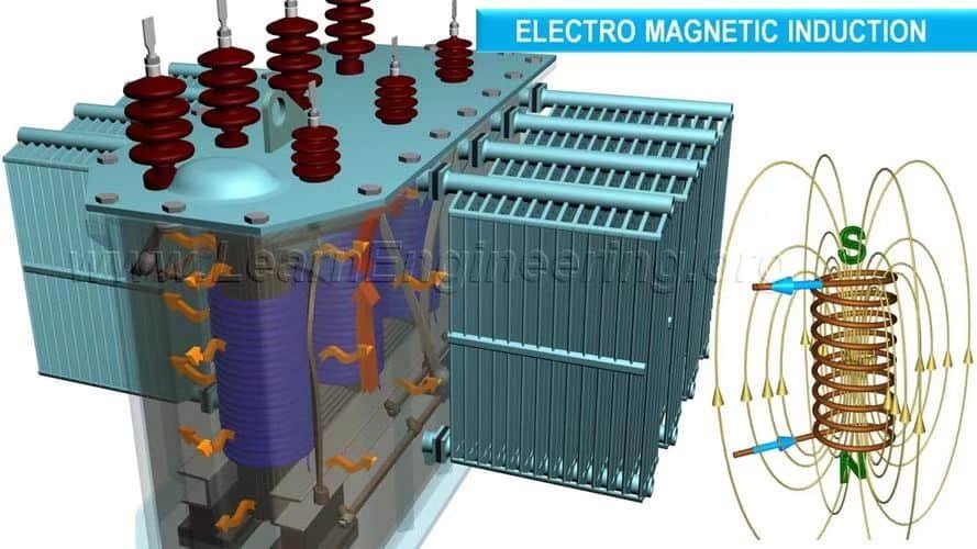
The main components of a transformer include the core (which channels magnetic flux), windings (which conduct electricity), insulating materials, the tank (enclosure), bushings (high-voltage terminals), cooling systems (like oil or fans), conservator (in oil-filled units), tap changers, and protective relays. Each of these components plays a vital role in ensuring efficient, safe, and stable voltage transformation.
These components form a tightly integrated system. Damage to even one can reduce efficiency, create overheating, or trigger failure. Let’s explore how each part works and how to identify common issues for better maintenance and reliability.
The transformer core carries electric current.False
The transformer core carries magnetic flux, not electric current. Current flows through the windings wrapped around the core.
Understanding the Transformer’s Primary Structure
Transformers are typically built around three major functional sections:
- Magnetic Circuit (Core)
- Electrical Circuit (Windings and Tap Changers)
- Support Systems (Insulation, Cooling, Enclosure)
Each of these houses several interdependent components.
🧲 1. Core – The Magnetic Backbone
Function: Directs the magnetic flux between primary and secondary windings with minimal losses.
| Component | Description |
|---|---|
| Core Laminations | Thin silicon steel sheets, stacked to reduce eddy currents |
| Yoke | Horizontal part connecting the vertical limbs |
| Limb/Leg | Vertical part where coils are wound |
| Clamps & Bracing | Mechanical supports to reduce vibration and noise |
Types of Core Construction:
| Core Type | Structure | Typical Use |
|---|---|---|
| Core-Type | Windings around limbs | Power distribution units |
| Shell-Type | Core surrounds windings | High-voltage applications |
🔍 Technical Note: A well-designed laminated core reduces hysteresis and eddy current losses, directly improving efficiency.
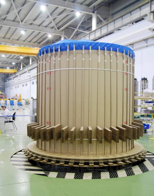
⚡ 2. Windings – The Electrical Pathways
Function: Carry primary and secondary electrical current and induce voltage by electromagnetic induction.
| Winding Type | Material | Description |
|---|---|---|
| Primary Winding | Copper/Aluminum | Connected to the input voltage |
| Secondary Winding | Copper/Aluminum | Delivers stepped-up/down voltage |
| Tertiary Winding | Copper | (Optional) Used for load balancing or grounding |
Winding Arrangements:
| Configuration | Description | Use Case |
|---|---|---|
| Concentric (cylindrical) | Windings placed concentrically | Common in power transformers |
| Sandwich or Disc | Alternating HV and LV disks | Reduces leakage reactance |
🔍 Design Fact: Copper is preferred for compact, high-efficiency designs, but aluminum is used where cost is a major concern.
🛡️ 3. Insulation System
Function: Electrically isolate conductive parts and prevent arcing or short-circuiting.
| Insulating Component | Description |
|---|---|
| Solid Insulation | Paper, pressboard, Nomex between windings |
| Liquid Insulation | Mineral oil or synthetic esters (acts also as coolant) |
| Barrier Systems | Blocks to direct oil and separate coils |
Common Insulation Failures:
- Moisture ingress
- Overheating (thermal aging)
- Partial discharge due to voltage spikes
🔍 Maintenance Tip: Regular Dissolved Gas Analysis (DGA) can detect insulation degradation before failure occurs.
🧯 4. Cooling and Temperature Control
Function: Dissipate heat from core and windings during operation.
| Cooling Method | Mechanism | Typical Application |
|---|---|---|
| ONAN (Oil Natural, Air Natural) | Oil circulates naturally, cooled by air | Small to medium transformers |
| ONAF (Oil Natural, Air Forced) | Fans increase air circulation | Larger, heavily loaded units |
| OFAF/OFWF | Oil and water pumped and cooled externally | Large substations and power plants |
Cooling Components:
- Radiators or heat exchangers
- Oil pumps
- Fans (forced air)
- Temperature sensors (RTDs or thermocouples)
🔍 Design Note: Cooling systems are selected based on transformer size, duty cycle, and ambient environment.
🧰 5. Tap Changer – Voltage Control Interface
Function: Adjust output voltage by changing winding connections.
| Type of Tap Changer | Operation | Description |
|---|---|---|
| Off-Load Tap Changer | Manual, de-energized | Set before operation |
| On-Load Tap Changer | Motor-driven, energized | Adjusts under load without shutdown |
Tap Range Example: ±10% in 1.25% steps
🔍 Maintenance Note: On-load tap changers should be inspected every 30,000 operations due to arc wear.
🔌 6. Bushings – Safe External Connections
Function: Allow high-voltage conductors to pass through the tank without electrical contact.
| Type | Voltage Class | Material |
|---|---|---|
| Porcelain | < 72.5 kV | Glazed ceramic |
| Composite/Polymer | ≥ 72.5 kV | Silicone rubber, epoxy |
Bushings must withstand:
- Electrical stress
- Thermal expansion
- Pollution (outdoor units)
🔍 Failure Sign: Cracks or oil leakage around bushings are early signs of insulation breakdown.
🛢️ 7. Conservator and Breather System
Function: Manage oil expansion and prevent moisture ingress.
| Component | Purpose |
|---|---|
| Conservator Tank | Accommodates oil expansion during heating |
| Silica Gel Breather | Absorbs moisture from ambient air entering tank |
| Buchholz Relay | Detects gas buildup indicating faults |
Breather Maintenance Tip: Replace silica gel when it turns pink (saturated with moisture).
🔒 8. Protection Devices and Monitoring
| Device/Component | Function |
|---|---|
| Buchholz Relay | Detects gas due to internal faults |
| Pressure Relief Valve | Releases gas to prevent tank rupture |
| Sudden Pressure Relay | Detects internal arc faults |
| Temperature Gauge | Measures winding or oil temperature |
| WTI/OTI Indicators | Winding Temp Indicator / Oil Temp Ind. |
Smart Monitoring: Modern transformers often include:
- SCADA connectivity
- IoT-based thermal monitoring
- Partial discharge sensors
Transformer Component Summary Table
| Main Component | Role in Transformer Function | Failure Consequences |
|---|---|---|
| Core | Directs magnetic flux | Higher losses, humming, overheating |
| Windings | Carry input/output current | Short-circuits, insulation failure |
| Insulation | Prevents voltage leaks | Arcing, breakdown |
| Cooling System | Manages operating temperature | Thermal runaway, shutdown |
| Tap Changer | Adjusts output voltage | Voltage instability, arcing |
| Bushings | High-voltage terminals | Oil leaks, flashovers |
| Conservator/Breather | Oil expansion, air filtration | Moisture contamination |
| Protection Relays | Early fault detection | Explosions, transformer fire |
Which Components Are Most Susceptible to Burning Out in a Transformer?
Transformer burnout incidents are among the most costly and disruptive failures in power systems. Often, the damage is not total—specific components fail while others remain intact. Identifying which parts are most vulnerable to burnout allows maintenance teams, engineers, and procurement departments to focus inspections, improve protection, and minimize unplanned outages. But which transformer components actually burn out most frequently? What causes them to fail thermally? And how can these failures be predicted and prevented? This article delivers a comprehensive, technical analysis of burnout-prone transformer parts and provides real-world data, diagnostic methods, and protection strategies.
The components most susceptible to burning out in a transformer are the windings (due to overcurrent or insulation failure), insulation systems (especially paper and oil under heat stress), bushings (due to flashover and contamination), tap changers (from arcing and contact wear), and core clamping structures (from hot spots and eddy currents). These parts endure high electrical and thermal stress and are often the origin of thermal runaway that leads to transformer failure.
Understanding which components fail most often and why is key to both preventive maintenance and long-term design improvements. This knowledge not only saves costs but also enhances reliability across entire power distribution systems.
Transformer oil never contributes to burnout.False
Transformer oil can degrade, lose its dielectric strength, and ignite under extreme temperature and arc conditions, contributing to burnout.
🔥 Top Burnout-Prone Components in a Transformer
1. Windings – The #1 Failure Source by Thermal Load
Windings are at the core of every transformer—literally and electrically—and they're the most common source of burnout.
Why They Burn Out:
- Overcurrent or sustained overloading
- Short-circuit faults that arc across turns
- Insulation degradation due to thermal aging or moisture
- Poor winding design leading to hot spots and uneven current density
Thermal Damage Symptoms:
- Charred copper or aluminum conductors
- Melted varnish or insulation tape
- Visible coil deformation
- High Dissolved Gas Analysis (DGA) readings (CO, CO₂, acetylene)
Thermal Resistance Limit:
Class A (105°C), Class B (130°C), Class F (155°C), Class H (180°C). Once exceeded, insulation failure is imminent.
| Winding Material | Burnout Risk Level | Notes |
|---|---|---|
| Copper | Moderate | Better thermal conductor |
| Aluminum | Higher | Lower thermal stability, cheaper |
| Resin-coated | Medium | Used in dry-type transformers |
🔍 Engineering Note: 70% of all transformer fires begin with internal winding faults triggered by insulation breakdown.
2. Insulation System – Paper and Oil Burn Under Stress
Transformers rely heavily on insulating materials to prevent arcing and dielectric failure.
Common Burnout Conditions:
- Heat buildup over time (above 90°C)
- Moisture ingress that reduces dielectric strength
- Sludge formation that restricts oil flow and cooling
- Partial discharge that carbonizes solid insulation
Thermal Behavior:
| Insulation Type | Ignition Point | Thermal Aging | Burnout Signs |
|---|---|---|---|
| Kraft paper | \~260°C | Severe at 110°C+ | Brittle, blackened, charred layers |
| Mineral transformer oil | \~170°C | Rapid degradation | Viscosity loss, sludge, color change |
| Synthetic esters | \~300°C | Slower aging | Better fire safety |
DGA Gas Indicators:
| Gas | Indicates |
|---|---|
| Acetylene (C₂H₂) | Arcing or severe overheating |
| Carbon Monoxide (CO) | Cellulose paper breakdown |
| Methane (CH₄) | Low-temperature hot spots |
🔍 Field Tip: Every 10°C rise above the rated temperature halves the insulation lifespan (Arrhenius law).
3. Bushings – External Yet Vulnerable to Thermal Flashover
Despite being outside the tank, bushings frequently contribute to burnout incidents.
Burnout Causes:
- Surface contamination from pollution or salt spray
- Partial discharge inside the condenser layers
- Thermal cycling that degrades the internal dielectric
- Loose or degraded gasket seals allowing oil seepage
Flashover Risk Zones:
- Porcelain surface (leakage current path)
- Connection points (corona discharge)
- Inside capacitive condenser layer (insulation cracks)
| Bushing Voltage Rating | Burnout Probability | Notes |
|---|---|---|
| ≤72.5 kV | Medium | Usually porcelain, manageable risk |
| 145–245 kV | High | Frequent in outdoor substations |
| >420 kV | Critical | Requires constant monitoring |
🔍 Infrared Test Tip: Temperature rise of >15°C compared to ambient on bushing surface is a red flag.
4. Tap Changers – Arcing and Mechanical Wear = Burnout Hotspot
On-load tap changers (OLTCs) are among the highest-maintenance parts and burn out often due to repeated operation under load.
What Goes Wrong:
- Contact erosion from arc discharge
- Oil contamination from arcing byproducts
- Switching errors or mechanical misalignment
- Timing failures during tap transition causing flashover
Signs of Tap Changer Burnout:
- Delayed tap response
- Excessive heat near tap housing
- Sludge or soot in tap changer oil compartment
- Abnormal sound during tap operation
| Tap Changer Type | Burnout Susceptibility | Best Practice |
|---|---|---|
| Off-load | Low | Only changed when de-energized |
| On-load (Resistive) | High | Arc extinguishing design needed |
| On-load (Reactive) | Medium | More robust but complex |
🔍 O\&M Note: Tap changer oil must be filtered every 2–3 years to prevent burnout from byproduct buildup.
5. Clamps and Structural Components – Indirect Victims of Hot Spots
Though non-electrical, mechanical parts such as core clamps, tank bracing, or bolt-insulation interfaces can burn out due to:
- Stray flux hot spots
- Loose metal parts acting as induction loops
- Poor contact surfaces generating heat
Visual Damage:
Burn marks on internal tank surfaces, warped metal brackets, melted epoxy or rubber spacers.
Hot Spot Detection Methods:
- Thermal imaging (IR scan)
- Sweep Frequency Response Analysis (SFRA)
- Contact resistance measurement across bolted joints
🔍 Design Insight: Clamps and tank parts can generate localized heating and create carbon trails, leading to phase-to-ground flashover.
Real-World Case Study: 25 MVA Transformer Fire – India, 2021
- Root Cause: High-resistance connection in the winding-to-bushing terminal
- Progression: Heat buildup → insulation breakdown → arc flash
- Outcome: Core melted, oil ignited, fire engulfed tank in 3 minutes
- Losses: \$1.2 million in equipment + 4-day industrial shutdown
- Lesson: Thermal scanning missed hotspot due to hidden connection point.
Transformer Burnout Risk Matrix
| Component | Burnout Risk | Burn Type | Maintenance Priority |
|---|---|---|---|
| Windings | Very High | Internal fire | Critical |
| Insulation | High | Combustion/sludge | Critical |
| Bushings | High | Flashover | High |
| Tap Changers | Medium-High | Arc erosion/burning | High |
| Core Clamps | Medium | Hot spot heating | Medium |
| Cooling Fans | Low-Medium | Overload, bearing fire | Medium |
What Causes Transformer Windings to Burn Out?
Transformer winding burnout is one of the most critical and expensive failures that can occur in a power distribution or industrial electrical system. When windings burn out, they don’t just damage the transformer—they often lead to outages, fires, and secondary equipment losses. The root causes behind this failure are complex and multifaceted, ranging from design flaws and aging to thermal stress and electrical abuse. In this article, we examine in-depth what exactly causes transformer windings to burn out, with supporting data, analysis, and proven prevention methods.
Transformer windings burn out primarily due to sustained overloading, short-circuits, insulation degradation (thermal or moisture-related), poor cooling, poor contact integrity, and manufacturing defects. These conditions lead to excessive heat generation within the coil turns, which weakens insulation, distorts windings, and eventually causes arcing or thermal breakdown.
Understanding these causes is essential for developing preventive strategies, performing effective diagnostics, and improving transformer reliability and safety. Let’s explore these burnout mechanisms in more detail.
Winding burnout is mostly due to electrical faults, not thermal issues.False
While electrical faults initiate some failures, it is the resultant heat—often unmitigated—that causes insulation breakdown and coil burnout. Thermal stress is the final trigger.
🔥 Key Causes of Transformer Winding Burnout
1. Sustained Overloading – Slow But Deadly
When a transformer is forced to carry current beyond its rated capacity for extended periods, the winding conductors (typically copper or aluminum) heat up due to I²R losses.
Consequences:
- Gradual temperature rise (>110°C)
- Accelerated insulation aging
- Thermal hot spots in densely wound sections
- Insulation embrittlement and eventual breakdown
| Loading Duration vs. Burnout Risk |
| Duration at 120% Load | Risk Level |
|---|---|
| 5 minutes | Low |
| 1 hour | Moderate |
| Continuous | Critical |
Real Case Example: A 630 kVA dry-type transformer at a cement plant in Pakistan ran at 130% for 3 hours/day. Within 2 years, winding paper was carbonized, resulting in phase-to-phase shorting.
🔍 Preventive Tip: Use load tap changers and digital overload relays to dynamically respond to load spikes.
2. Short-Circuits – Instantaneous Destruction
Short-circuits cause very high fault currents, often several times the rated load. These faults last milliseconds but cause intense electromagnetic forces and thermal rise.
Types of Short-Circuits:
| Fault Type | Typical Cause | Resulting Damage |
|---|---|---|
| Phase-to-phase | Insulation breach | Arc across windings |
| Phase-to-ground | Insulation crack or breakdown | Ground fault, thermal arc |
| Inter-turn (within coil) | Mechanical vibration | Local heating, hot spot |
| Fault Current vs. Burnout |
| Fault Current (kA) | Windings Affected |
|---|---|
| <5 kA | Localized damage |
| 5–10 kA | Full coil charring |
| >10 kA | Complete meltdown |
🔍 Protection Tip: Install fast-acting fuses and differential protection relays to trip supply within 40–80 ms of fault detection.
3. Insulation Breakdown – The Silent Killer
Transformer winding insulation, typically made of cellulose paper, epoxy varnish, or Nomex, degrades with:
- Thermal aging (high internal temperatures)
- Moisture ingress (reduces dielectric strength)
- Acid formation in oil from oxidation
- Partial discharges or corona effects
Insulation Class and Thermal Limits:
| Insulation Class | Max Temp (°C) | Lifespan @ Max Temp |
|---|---|---|
| A | 105 | \~20,000 hrs |
| B | 130 | \~16,000 hrs |
| F | 155 | \~12,000 hrs |
| H | 180 | \~10,000 hrs |
Insulation Burnout Signs:
- Brown to black discoloration
- Loss of flexibility
- Brittle or flaking insulation
- Formation of carbon paths
🔍 Diagnostic Tip: Perform DGA (Dissolved Gas Analysis) and Polarization Index (PI) tests to assess insulation health periodically.
4. Inefficient or Failed Cooling Systems
Thermal dissipation in power transformers is often managed by:
- Oil circulation (ONAN, ONAF)
- Fans (air-forced)
- Heat exchangers or radiators
- Natural convection in dry types
If cooling fails due to:
- Clogged radiators
- Oil pump malfunction
- Air blockage or fan failure
- Ambient temperature spikes
…heat builds up around the windings, causing:
- Localized overheating
- Breakdown of adjacent insulation
- Spiral burnout
Cooling Performance vs. Burnout Risk Table
| Cooling Type | Vulnerability | Maintenance Need |
|---|---|---|
| ONAN (Oil-Natural) | Medium | Oil level and DGA |
| ONAF (Oil + Fan) | High | Fan/louver inspection |
| Dry Type (Air) | Medium–High | Dust filters and ventilation |
🔍 Monitoring Tip: Install RTDs (Resistance Temperature Detectors) near coil heads for real-time thermal tracking.
5. Loose Terminal or Connection Points
Loose joints or corroded connections at:
- HV/LV terminals
- Bushing-to-coil joints
- Tap changer arms
- Parallel winding link points
…cause high contact resistance, which leads to localized heating, arcing, and eventual winding burnout.
Common Root Causes:
- Poor torque during assembly
- Vibration loosening over time
- Thermal cycling (expansion/contraction)
- Corrosion from humid environments
Thermal Image Examples:
- Connector running 35°C hotter than winding
- Arcing marks or oxidation discoloration
- Audible buzzing or hissing near the fault
🔍 Correction Method: Periodic torque retesting and infrared thermography during load cycles.
6. Manufacturing Defects and Poor Design
In poorly manufactured transformers or poorly specified units, burnout may be triggered by:
- Uneven winding stress distribution
- Insufficient insulation layering
- Sharp bending of winding leads
- Improper varnish curing or incomplete drying
- Wrong core-to-coil clearances
Post-Manufacture QC Tests That Help:
| Test Name | Purpose |
|---|---|
| Impulse Test | Simulates lightning/surge resilience |
| Heat Run Test | Measures temp rise under load |
| Turn Ratio Test | Checks winding integrity |
| Inter-turn Insulation Test | Finds weak points in coil layers |
🔍 Vendor Advice: Always request type test reports and factory routine test data from your transformer manufacturer before purchase.
Transformer Winding Burnout Diagnostic Table
| Cause | Diagnostic Method | Preventive Measure |
|---|---|---|
| Overloading | Load profiling, temp sensors | Load management, OLTC |
| Short-circuits | Relay trip records, visual inspection | Fast breakers, surge protection |
| Insulation failure | DGA, insulation resistance, PI | Regular oil testing, dry-out systems |
| Cooling inefficiency | IR scanning, temp gauge | Radiator cleaning, fan servicing |
| Loose connections | Infrared scans, voltage drop test | Torque checks, joint greasing |
| Manufacturing flaws | Partial discharge test, SFRA | Use certified OEMs, quality inspections |
How Does Insulation Degrade and Burn in Transformers?
Transformer insulation is one of the most critical components ensuring the electrical integrity and safety of the system. It separates high-voltage and low-voltage windings, prevents short-circuits, and contains internal faults. However, insulation systems—comprising materials like Kraft paper, varnish, epoxy resin, Nomex, and transformer oil—are not immune to degradation. Over time, environmental, electrical, thermal, and chemical stressors degrade insulation, and in severe cases, cause it to ignite, burn, or explode. So, how exactly does insulation break down and burn? What stages lead to this catastrophic failure? This technical guide explores the lifecycle of insulation degradation, its failure modes, indicators, and prevention strategies.
Transformer insulation degrades due to prolonged thermal aging, electrical stress, moisture contamination, oxidation, and partial discharge, which cause molecular breakdown of materials like paper, oil, and resin. This degradation reduces dielectric strength, eventually allowing internal arcing and thermal runaway, which ignites the insulation and leads to burning, carbon tracking, or total failure.
Understanding how insulation fails is key to preventing transformer fires, outages, and expensive repairs. This article provides deep insights based on lab-tested behavior, industry data, and case studies.
Insulation in transformers is designed to last indefinitely if installed properly.False
Even with perfect installation, insulation materials age over time due to heat, oxidation, and environmental conditions, and must be regularly monitored and maintained.
🔥 Lifecycle of Insulation Degradation in Transformers
1. Thermal Aging – The Slow Breakdown of Molecular Bonds
Every insulation material has a thermal class defining its maximum operating temperature (Class A: 105°C, B: 130°C, F: 155°C, H: 180°C). When operated near or above this temperature:
- Cellulose (Kraft paper) begins to depolymerize
- Epoxy varnish softens and cracks
- Transformer oil oxidizes and forms sludge
| Insulation Class vs. Aging Curve |
| Class | Max Temp (°C) | Lifespan @ Max Temp (hrs) | Degradation byproduct |
|---|---|---|---|
| A | 105 | \~20,000 | Water, CO, CO₂ |
| B | 130 | \~16,000 | Methanol, acids |
| F | 155 | \~12,000 | Acetylene, sludge |
| H | 180 | \~10,000 | Aromatic hydrocarbons |
Arrhenius Equation Rule: For every 10°C increase, insulation lifespan halves.
🔍 Detection Method: Use fiber-optic thermal probes embedded near coil windings for accurate hotspot monitoring.
2. Moisture Ingress – Killer of Dielectric Strength
Cellulose-based insulation is hygroscopic, meaning it absorbs water from the environment. Just 2% moisture by weight can halve the dielectric strength of paper and increase the risk of partial discharge and arcing.
| Moisture Content (%) | Dielectric Strength Loss | Risk Level |
|---|---|---|
| 0.5 | Negligible | Safe |
| 1.0 | \~10–20% | Moderate |
| 2.0 | \~40–50% | Critical |
| >3.0 | \~60–80% | Imminent Failure |
Causes of Moisture Ingress:
- Leaky gaskets or breathers
- Poor oil processing or dry-out
- Ambient humidity in unsealed enclosures
- Aging that releases moisture from cellulose
🔍 Test Method: Karl Fischer titration or in-situ moisture-in-oil sensors for real-time tracking.
3. Oxidation and Acid Formation – Silent Corrosion Agent
As transformer oil and varnish age, they react with oxygen, especially at elevated temperatures.
Resulting Effects:
- Formation of acids → which degrade cellulose and corrode metal surfaces
- Increase in tan delta (dissipation factor) → indicating insulation loss
- Sludge formation → which clogs radiator pipes and restricts cooling
| Oxidation Impact Table |
| Oxidation Product | Effect on Insulation |
|---|---|
| Acids | Weakens cellulose bonds |
| Sludge | Traps heat and particles |
| Carbon particles | Initiate partial discharge |
🔍 DGA Warning Signs: High furan levels, CO/CO₂ ratios >10, and increased moisture signal insulation oxidation.
4. Partial Discharge – The Micro Arcing Menace
Partial discharge (PD) is the localized dielectric breakdown in a small portion of insulation under high voltage stress. Repeated PD leads to:
- Carbon tracking along the insulation surface
- Treeing, where microchannels develop into complete failure paths
- Thermal punctures and surface pitting
| PD Level vs. Damage Risk |
| PD Activity (pC) | Condition | Action Needed |
|---|---|---|
| <100 | Normal | Routine monitoring |
| 100–500 | Warning | Schedule maintenance |
| >500 | Severe | Immediate intervention |
🔍 Test Method: Use PD detection via ultrasonic sensors, acoustic emissions, or high-frequency current transformers (HFCT).
5. Electrical Stress – Voltage Surges and Field Distortion
Insulation is rated for normal operating voltages and surge voltages (BIL – Basic Insulation Level). When exceeded due to:
- Lightning strikes
- Switching surges
- Ferroresonance
- Uneven field gradients in poor winding designs
…the insulation undergoes puncturing, which causes:
- Pinholes in varnish
- Perforated paper barriers
- Internal arcing within layers
- Surface flashovers
Dielectric Breakdown Strengths:
| Material | Breakdown Voltage (kV/mm) | Notes |
|---|---|---|
| Kraft paper | \~10–15 | Drops when aged or moist |
| Transformer oil | \~30–50 | Drops when contaminated |
| Epoxy/Nomex | \~20–25 | Stable under dry conditions |
🔍 Preventive Tip: Ensure surge arresters and shielding tapes are installed near terminals.
🔥 When Does Insulation Actually Burn?
Insulation burns when the thermal energy from internal arcs or overheating exceeds its ignition temperature and there's sufficient oxygen present.
| Material | Ignition Temp (°C) | Burn Behavior |
|---|---|---|
| Kraft paper | \~260 | Rapid flame, black soot |
| Transformer oil | \~170 | Burns if vaporized |
| Epoxy resin | \~380–450 | Melts then chars |
| Nomex | >400 | High resistance to flame |
Ignition Triggers:
- Inter-turn arcing from insulation puncture
- Corona discharge near terminals
- Oil vapor ignition from arcs
- Thermal runaway in cooling failure scenarios
Flame Spread Indicators:
- Charred insulation debris
- Oil ignition and tank overpressure
- Release of combustion gases (acetylene, hydrogen)
🔍 Real Incident: In Malaysia (2018), a 2.5 MVA transformer caught fire when a loose bushing terminal caused arcing. The insulation around the terminal ignited, escalating to a tank rupture within minutes.
Transformer Insulation Burnout Indicator Chart
| Failure Mechanism | Symptoms | Detection Method | Recommended Action |
|---|---|---|---|
| Thermal aging | Darkened paper, acid oil | DGA, visual inspection | Load reduction, dry-out |
| Moisture absorption | Brittle insulation, gas bubbles | Moisture sensor, PI test | Dehydration, oil processing |
| Oxidation | Sludge, high acidity | TAN (Total Acid Number) test | Oil filtration |
| Partial discharge | Pitting, audible noise | PD detector, HFCT, ultrasound | Replace insulation, seal voids |
| Electrical overstress | Puncture holes, flashover | IR scan, surge arresters audit | Improve shielding, spacing |
What Happens When the Tap Changer or Bushings Burn Out?
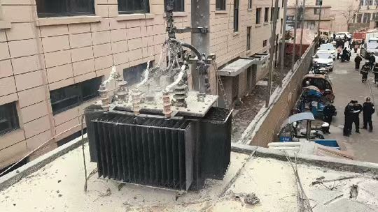
Tap changers and bushings are critical auxiliary components in transformers, responsible for voltage regulation and electrical interface between the transformer and the external circuit. When either component burns out, it can lead to catastrophic transformer failure, substation fires, voltage instability, or total system shutdown. This article provides a detailed technical insight into what happens when these components fail due to burning, how to identify the signs early, and how to mitigate the damage.
When a transformer tap changer or bushing burns out, it causes electrical arcing, insulation failure, and a sudden interruption of current flow or voltage regulation. This can lead to overheating, internal short circuits, oil fires, tank rupture, and widespread power outages. Tap changer burnout typically results from contact erosion or overloads, while bushing failures stem from moisture ingress or insulation breakdown.
Understanding the burn-out mechanisms of tap changers and bushings is essential for transformer reliability and fire prevention. Let’s explore in detail the effects, diagnostics, and prevention methods of these high-risk failure modes.
Burned tap changers and bushings can continue to operate temporarily until repair.False
Once burned, these components pose immediate electrical and thermal hazards, and continuing operation risks explosion, fire, or phase-to-ground faults. Immediate shutdown is recommended.
🔧 What Happens When a Tap Changer Burns Out?
Tap changers are responsible for regulating voltage by selecting different winding taps within the transformer. There are two types:
- On-Load Tap Changer (OLTC) – operates while transformer is energized
- Off-Circuit Tap Changer (OCTC) – operated only when de-energized
When a tap changer burns out, the following consequences occur:
1. Contact Erosion and Arcing
Tap changers have moving contacts that switch between taps. Over time, these contacts erode due to:
- Electrical arcing during switching
- Overcurrent stress
- Inadequate lubrication or oil contamination
As erosion worsens, the contact resistance increases, causing:
- Hotspots exceeding 300°C
- Carbonization of insulating material
- Internal arcing or flashover
| Tap Changer Fault Effect Table |
| Burn Mode | Resulting Failure |
|---|---|
| Contact welding | Cannot shift tap, fixed output voltage |
| Open contact | Arc ignition, oil degradation |
| Carbon buildup | Poor voltage regulation, heat rise |
🔍 Symptoms:
- Tap changer gets stuck in one position
- Audible hissing or crackling sounds
- Rising oil temperature and bubbling
- Abnormal gas generation (C₂H₂, C₂H₄) in DGA
2. Degraded Insulating Medium (Oil or Resin)
OLTCs are often filled with separate insulating oil or vacuum bottles. When a burn occurs:
- Oil decomposes, generating combustible gases
- Insulating strength plummets, allowing arc paths
- Explosive pressure may rupture the tap changer chamber
| Tap Changer Oil Degradation |
| Oil Parameter | Normal Value | Failure Condition |
|---|---|---|
| Dielectric Strength | >40 kV | <15 kV |
| Water Content | <20 ppm | >100 ppm |
| TAN (Acid Number) | <0.1 mgKOH/g | >0.3 mgKOH/g |
🔍 Prevention Tip: Periodic oil sampling from OLTC compartment, not just the main tank.
🔌 What Happens When a Transformer Bushing Burns Out?
Bushings are insulated passageways that carry high voltage through the transformer tank to the windings. They must withstand:
- Electrical stress
- Environmental exposure
- Mechanical vibration
When a bushing burns out, it can cause one of the most dangerous failures in power equipment.
1. Partial Discharge and Internal Arcing
Over time, moisture, aging insulation, and contamination cause partial discharge (PD) within the bushing:
- PD leads to carbonization of insulation
- Voltage stress concentrates in degraded zones
- Full internal flashover occurs, rupturing the bushing
| PD Activity vs. Bushing Health |
| PD Level (pC) | Health Status | Action |
|---|---|---|
| <100 | Normal | Monitor quarterly |
| 100–500 | Degraded | Replace within months |
| >500 | Critical | Immediate shutdown |
2. Explosion or External Flashover
Burned bushings can:
- Ignite the surrounding oil, triggering a fire
- Cause flashover to the transformer tank or ground
- Crack or explode, ejecting porcelain or resin shards
| Bushing Failure Outcome Table |
| Failure Mode | Consequences |
|---|---|
| Internal flashover | Tank rupture, fire, total outage |
| Surface tracking | Arcing across surface, black marks |
| Thermal runaway | Smoke, heat plume, melting resin |
🔍 Diagnostic Signs:
- Cracks in porcelain or oil seepage
- Hotspot >90°C on thermal camera
- Increase in tan delta or capacitance
- Rising hydrogen, CO, C₂H₂ in DGA
⚠️ Combined Tap Changer + Bushing Failure: Worst-Case Scenario
In some incidents, bushing degradation causes a voltage spike that stresses the tap changer, or vice versa. This can cause:
- Synchronized arc ignition
- Transformer tank overpressure
- Substation fires or cascading failures
Real Case Example: In 2017, a 66kV substation in Chile suffered a fire when an OLTC failed mid-operation. The arc ignited vaporized oil from a nearby cracked bushing. The fire took 2 hours to extinguish and damaged the entire switchyard.
Transformer Failure Impact Chart from Tap Changer or Bushing Burnout
| Component Failed | Immediate Symptoms | Secondary Damage | Response Required |
|---|---|---|---|
| Tap Changer | Voltage drop, overheating | Coil insulation damage | Shut down and inspect |
| Bushing | Arc sound, visible charring | Tank fire, core damage | Emergency shutdown |
| Both | Explosive failure, total loss | Fire spread, environmental risk | Fire suppression + full replacement |
Diagnostic and Monitoring Strategy
| Component | Monitoring Tool | Maintenance Action |
|---|---|---|
| Tap Changer | Motor current monitor, acoustic emission | Clean contacts, replace arc quenchers |
| Bushing | Tan delta test, PD detector, IR camera | Replace aged units, moisture proofing |
| Oil in tap/bushing chamber | DGA, dielectric test | Oil filtering, moisture removal |
What Are the Visible and Detectable Signs of Transformer Burnout?
Transformer burnout is a critical failure event that poses immediate risks to electrical infrastructure and safety. Early detection of burnout—whether partial or full—is crucial to prevent outages, equipment loss, or fire. Burnouts can affect windings, insulation, bushings, tap changers, or core components, and they manifest in a variety of physical and diagnostic signals. This article provides a complete technical overview of visible and detectable signs of burnout, and guides operators, maintenance teams, and engineers on how to identify, confirm, and act on those signs using professional tools and techniques.
The visible and detectable signs of transformer burnout include oil leaks, discoloration or charring of components, smoke or odor, loud noise during operation, abnormal temperature rise, and sudden performance drops. Detectable diagnostic signs include high gas levels in DGA, changes in tan delta, unusual partial discharge activity, increased vibration, and thermal hotspots on infrared scans.
Transformers rarely fail without warning. The earlier these signs are recognized and diagnosed, the more likely the system can be safely shut down before catastrophic failure occurs. This article explores the topic in depth with visuals, technical tables, and real-world data.
A burned transformer always looks visibly damaged on the outside.False
Some transformer burnouts, especially winding or insulation faults, may occur internally without external signs until severe failure develops. Diagnostic tests are essential.
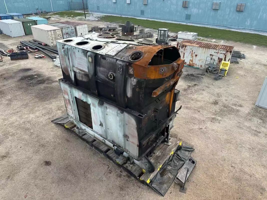
🔍 1. Visual Signs of Burnout
A. External Discoloration and Carbonization
Burnout often leaves visible soot or dark residue around bushings, tap changers, or tank weld seams. This indicates:
- Oil ignition residue
- Insulation burnout smoke
- Carbon tracking due to partial discharge
| Location | Burnout Sign | Severity |
|---|---|---|
| Bushing collars | Black streaks, resin cracks | High |
| Tap changer panel | Darkened casing, oil stains | Medium |
| Tank surface | Bubbling paint, soot marks | High |
B. Oil Leakage or Bubbling
- Leaking gaskets indicate internal pressure or overheating
- Oil bubbling on inspection means internal arcing
Visible signs include:
- Wet streaks on the tank
- Oil puddles beneath
- Foaming or discoloration in conservator
🔍 Field Tip: A mirror placed near bushings can help detect hidden backside leaks during inspection.
C. Smoke, Burning Smell, or Fire Debris
Burning insulation (especially cellulose or varnish) emits:
- A sharp, acrid smell (distinctly chemical)
- Gray or black smoke plumes from vents or ruptures
- Residue of charred insulating paper
Odor Markers:
| Smell Detected | Likely Fault Source |
|---|---|
| Bitter acrid smell | Paper insulation burnout |
| Burnt plastic | Winding varnish degradation |
| Oily smoke | Oil ignition or flashover |
D. Deformed or Cracked Components
Prolonged overheating or internal arcing may warp:
- Bushing porcelain or composite shells
- Tap changer enclosures
- Radiator fins (due to oil overheat)
🔍 Safety Tip: Never approach cracked bushings without proper PPE—they can shatter under load.
📈 2. Detectable Diagnostic Signs of Burnout
A. Dissolved Gas Analysis (DGA)
The most trusted burnout diagnostic method. Specific gases signal different fault types:
| Gas Type | Primary Source | Burnout Indication |
|---|---|---|
| Hydrogen (H₂) | Corona discharge | Early insulation fault |
| Acetylene (C₂H₂) | Arcing | Severe burn or short circuit |
| Methane (CH₄) | Overheating | Moderate insulation damage |
| CO/CO₂ | Paper decomposition | Winding burnout |
Burnout Indicator Ratios (Rogers Ratio Method):
| Gas Ratio | Threshold | Interpretation |
|---|---|---|
| C₂H₂ / C₂H₄ | >1 | Arcing (burnout likely) |
| CO / CO₂ | >0.1 | Paper burnout |
| CH₄ / H₂ | >0.5 | Thermal fault |
B. Infrared Thermography (Thermal Imaging)
Thermal scans detect hotspots and heat leakage caused by:
- Poor contact in bushings
- Internal coil heating
- Tap changer resistance increase
| Temperature Rise (°C) | Interpretation |
|---|---|
| <20°C | Normal |
| 20–40°C | Warning – load check |
| >40°C | Critical – possible burnout |
🔍 Usage Tip: Scan during peak load hours for best differential readings.
C. Partial Discharge (PD) Monitoring
Partial discharges occur in degrading insulation and precede full burnout. Detect using:
- Ultrasonic sensors
- UHF antenna inside tank
- HFCT on grounding connections
| PD Level (pC) | Status | Action |
|---|---|---|
| <100 | Acceptable | Routine monitor |
| 100–500 | Degrading | Schedule repair |
| >500 | Severe risk | Immediate shutdown |
D. Electrical Test Deviations
- Insulation Resistance (IR) – Sudden drops indicate water or burned insulation
- Power Factor (tan δ) – Increase signals dielectric loss
- Capacitance – Changes reflect layer damage or displacement
- Turns Ratio Test – Variance indicates winding or tap damage
| Test | Burnout Indicator |
|---|---|
| IR | <10 MΩ (HV side) |
| Tan δ | >0.7% @ rated frequency |
| Capacitance | ±10% deviation from baseline |
| TTR | Phase imbalance or drift >0.5% |
E. Vibration and Sound Monitoring
Burnouts can trigger:
- Vibration from winding movement
- Humming noise from core saturation
- Buzzing/crackling from arcing
🔍 Install acoustic sensors to monitor transformer casing resonance. Abnormal vibration spectrum points to mechanical instability or internal arcs.
🔧 Early Warning Signs vs. Emergency Symptoms
| Early Warning Sign | Interpretation | Response |
|---|---|---|
| Slight oil discoloration | Minor insulation stress | Monitor and test oil |
| Elevated DGA gases | Pre-burn condition | Run confirmatory tests |
| Hotspot >40°C | Coil heating or bad contact | IR scan, load reduction |
| Crackling noise | PD or arc discharge | Ultrasonic testing |
| Emergency Symptoms | Interpretation | Response |
|---|---|---|
| Thick smoke or odor | Active combustion | Emergency shutdown |
| Visible soot or carbon | Flashover or insulation burnout | Evacuate and inspect |
| Tripped breakers | Short circuit due to coil burnout | Analyze relay event logs |
| Exploded bushing or arc | Physical damage, high fault current | Notify fire/rescue teams |
Conclusion
Transformer burnout is rarely random—it is almost always the result of sustained stress, neglect, or abnormal operating conditions. The most commonly affected parts are the windings (due to overcurrent), insulation systems (due to thermal aging and moisture), and tap changers or bushings (due to arcing or loose connections). Early detection methods such as thermal scanning, DGA (Dissolved Gas Analysis), and regular inspection can dramatically reduce the risk of catastrophic failure. Understanding what burns out and why is essential for ensuring transformer health and preventing costly outages or fires.
FAQ
Q1: What typically burns out in a transformer?
A1: When a transformer fails, the components most likely to burn out are:
Windings (Copper or Aluminum Coils): These carry the electrical current and are prone to overheating due to overloading or short circuits.
Insulation Material: This prevents electrical arcing between windings. It can degrade from heat, moisture, or aging.
Tap Changer Contacts: In load tap changers, excessive arcing or wear can lead to localized burning.
Core Lamination: Though less common, severe faults can cause hot spots in the iron core.
These failures typically result from thermal stress, overvoltage, or insulation breakdown.
Q2: How does transformer winding burnout occur?
A2: Winding burnout usually happens due to:
Prolonged overloading, causing the temperature to exceed safe limits.
Short circuits or electrical faults, which rapidly increase current flow and generate heat.
Poor cooling or ventilation, especially in oil-immersed units with blocked radiators.
Harmonics and voltage spikes, which can damage winding insulation and trigger flashover.
Q3: Can insulation failure lead to transformer burnout?
A3: Yes. Insulation failure is a primary cause of transformer burnout. When the insulation breaks down:
Internal arcing can occur between windings or to the core.
Thermal runaway may lead to fire or melting of nearby components.
Accelerated aging of the transformer happens, reducing its lifespan.
Proper oil testing and insulation monitoring help prevent this.
Q4: What are early signs of transformer burnout?
A4: Warning signs include:
Overheating or increased operating temperature
Unusual humming or buzzing sounds
Oil discoloration or gas buildup in oil-immersed models
Burnt smell or visible smoke
Reduced insulation resistance or dielectric breakdown
Timely diagnostics like DGA (Dissolved Gas Analysis) or thermal imaging can detect early damage.
Q5: How can transformer burnout be prevented?
A5: Preventive measures include:
Proper load management and avoiding overloading
Regular maintenance and oil quality checks
Use of protective relays and surge arresters
Cooling system inspections
Monitoring systems for temperature, moisture, and electrical anomalies
A well-maintained transformer can serve 20–40 years without major burnout issues.
References
"Common Transformer Failures and Their Causes" – https://www.electrical4u.com/transformer-failure-analysis
"IEEE Guide for Transformer Winding Failures" – https://ieeexplore.ieee.org/document/8045584
"Understanding Transformer Burnout" – https://www.powermag.com/transformer-burnout-causes-and-prevention
"DGA: Detecting Internal Transformer Issues" – https://www.se.com/transformer-oil-dga-guide
"Transformer Maintenance Handbook" – https://www.energycentral.com/c/ee/transformer-maintenance-best-practices
"Thermal Aging of Transformer Insulation" – https://www.sciencedirect.com/transformer-insulation-aging
"Siemens: Transformer Condition Monitoring" – https://www.siemens-energy.com/monitoring-transformers
"NFPA: Fire Hazards in Burned Transformers" – https://www.nfpa.org/transformer-safety