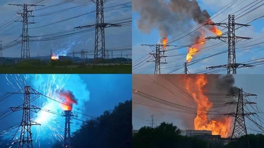
A short circuit is one of the most severe electrical faults a power system can experience. It occurs when an unintended connection allows current to travel along an unintended path with little or no electrical resistance. For transformers and power systems, this can lead to mechanical stress, overheating, and catastrophic failure if not managed correctly. Understanding the consequences and dynamics of a short circuit is essential for electrical engineers, operators, and maintenance personnel.
What Physically Happens in a Transformer During a Short Circuit?
Short circuits are among the most violent and dangerous events that can occur in power systems—and transformers, being critical grid components, are particularly vulnerable. When a short circuit occurs, the transformer experiences an instantaneous surge of current—many times its rated capacity—which can cause intense mechanical forces, magnetic stress, heating, and even internal arcing. If not properly designed to withstand these extreme conditions, a transformer can suffer catastrophic failure within milliseconds. Understanding the physical phenomena inside a transformer during a short circuit is essential for engineers, asset managers, and protection designers.
During a short circuit, a transformer experiences a rapid rise in fault current that produces intense electromagnetic forces acting on its windings. These forces can deform, displace, or collapse the windings if mechanical bracing is insufficient. The sudden current surge also causes extreme heat generation, possible insulation breakdown, and pressure waves that stress the core and tank. Internal arcing, dielectric fluid breakdown, and magnetic core saturation may occur. If not cleared promptly by protection systems, these effects can permanently damage the transformer or lead to explosion.
Short circuits produce purely thermal stress in transformers.False
Short circuits generate both thermal and intense mechanical forces due to magnetic field interactions.
Transformer windings can be physically displaced by fault currents.True
High electromagnetic forces during faults can bend or move windings, especially if they lack structural bracing.
Transformers must be designed to withstand dynamic short-circuit forces as per IEC 60076-5.True
Short-circuit withstand capability is a critical design requirement under international standards.
Electromagnetic and Mechanical Forces During Short Circuit
The most critical physical reaction in a transformer short circuit is the intense Lorentz force between current-carrying conductors.
| Force Type | Mechanism |
|---|---|
| Radial Force | Pushes winding turns outward or inward, like a spring compression |
| Axial Force | Pushes top and bottom windings away from each other or toward the core |
| Shear Force | Attempts to twist or slide windings laterally across each other |
These forces are proportional to the square of the short-circuit current:
$$
F \propto I^2
$$
If short-circuit current is 20× the rated current, the resulting mechanical force is 400× greater than during normal operation.
Heating and Dielectric Stress
| Parameter | Short-Circuit Impact |
|---|---|
| Copper Losses (I²R) | Increase exponentially, causing rapid temperature rise |
| Oil Temperature | Can rise 100°C or more in a few seconds |
| Insulation Breakdown | Due to heat and partial discharges under high stress |
| Gas Generation (DGA) | Fault gasses like acetylene and ethylene are rapidly produced |
If thermal limits are exceeded, cellulose insulation chars, bubbles form, and dielectric breakdown may occur.
Structural and Core Reactions
| Component | Physical Response |
|---|---|
| Core Clamps | May loosen due to vibration or magnetic shock |
| Tank Walls | Deform or bulge if internal pressure surges from gas evolution |
| Conservator | Oil surge may trigger Buchholz relay as internal arcing causes gassing |
| Bushings | Flashover risk due to voltage transients and insulation degradation |
In severe cases, the entire transformer may vibrate or hum violently due to sudden core magnetostriction under saturated conditions.
Sequence of Physical Events During a Typical Fault
| Milliseconds (ms) | Physical Event |
|---|---|
| 0–1 ms | Short-circuit current spikes instantly (peak fault current) |
| 1–5 ms | Magnetic fields induce strong forces on windings |
| 5–10 ms | Winding support begins to flex or shift; oil heating begins |
| 10–30 ms | Arc flash or partial discharge may ignite in insulation gaps |
| 30–100 ms | Core and tank vibrate; gas generation starts; Buchholz trips (if equipped) |
| 100+ ms | If not cleared, internal failure escalates into irreversible damage |
Protection relays are typically set to detect and isolate faults within 30–100 ms to prevent structural damage.
Design Requirements to Withstand Short Circuits
IEC 60076-5 specifies short-circuit testing to ensure transformer resilience:
| Design Feature | Purpose |
|---|---|
| Winding Bracing and Clamping | Prevent radial and axial movement |
| Duct Spacers and Block Supports | Resist magnetic pressure on winding stacks |
| Tank Pressure Relief Devices | Release pressure from internal arcing |
| High-Grade Cellulose Insulation | Withstand short-term thermal stress |
| Oil with High Dielectric Strength | Resist flashover and support voltage gradients |
Factory short-circuit withstand testing simulates worst-case events with fault currents injected under controlled conditions.
Data Table: Short-Circuit Effects Based on Transformer Size
| Transformer Rating | Fault Current (typical) | Radial Force per Turn | Short-Circuit Duration Tolerance |
|---|---|---|---|
| 1 MVA | ~15–20 kA | ~200 N | ~0.5 seconds max |
| 10 MVA | ~25–30 kA | ~1000 N | ~0.25 seconds max |
| 100 MVA | ~40–50 kA | ~2500–3000 N | <0.1 seconds preferred |
The magnitude of force increases quadratically with current and linearly with conductor length and proximity.
Case Study: Windings Deformed by Repeated Faults
In a 132 kV substation transformer, undetected line faults caused repeated short-circuit events. Initial protection failures allowed current to persist for over 200 ms on each occasion. Inspection revealed:
- Axial compression of HV winding
- Radial bowing of LV winding, evident from DGA and sweep frequency tests
- Permanent displacement of leads and oil degradation
The unit had to be rewound at significant cost—highlighting that even “temporary” faults leave permanent scars.
What Are the Main Causes of Short Circuits in Power Systems?
Short circuits in power systems are sudden, high-current faults that bypass normal load paths—causing voltage collapse, equipment damage, and possible power outages. These faults are typically unintentional contacts between phases or between phase and ground. The root causes are diverse, ranging from environmental events like lightning and flooding to insulation failure, human error, and mechanical breakdown. If not identified and mitigated, short circuits can result in transformer damage, arc flash incidents, or cascading grid instability. Understanding the main causes is key to implementing effective protection and prevention strategies.
The main causes of short circuits in power systems include insulation failure due to aging or thermal stress, environmental events like lightning strikes or wildlife contact, mechanical damage from vibration or poor installation, contamination from moisture or dust, and operational errors such as miswiring or equipment misuse. These faults can occur anywhere along the network—from transmission lines to transformers, switchgear, and underground cables—and must be rapidly cleared by protective relays and breakers.
Short circuits only occur due to equipment failure.False
Short circuits can result from external environmental factors, human error, or foreign object contact—not just equipment failure.
Lightning is a common external cause of transmission line short circuits.True
Lightning strikes can bridge insulators or flashover lines, creating a low-impedance path between conductors or ground.
Contaminated or wet insulation increases the risk of flashover and short circuit.True
Moisture or pollution on insulating surfaces lowers dielectric strength, making flashover more likely.
1. Insulation Failure in Equipment
| Component Affected | Cause of Failure |
|---|---|
| Transformer windings | Aging cellulose, overheating, partial discharge |
| Cables | Water treeing, mechanical stress, UV exposure |
| Circuit breakers | Arc erosion, dielectric degradation |
| Bushings | Oil leaks, contamination, surface tracking |
Once dielectric breakdown occurs, voltage surges or load current can force arcing between conductive parts—leading to a short.
2. Environmental Factors
| Source | Mechanism |
|---|---|
| Lightning Strikes | High-energy impulse causes insulation flashover |
| Flooding or Water Ingress | Causes insulation breakdown in cables and switchgear |
| Windborne Debris | Brings conductive material into contact with phases |
| Pollution and Dust | Forms conductive paths on insulators, especially with moisture |
Outdoor insulators and unsealed enclosures are highly vulnerable in coastal, industrial, or rainy environments.
3. Wildlife and Vegetation Intrusion
| Intrusion Type | Effect |
|---|---|
| Birds or Squirrels | Bridge live conductors or short phase-to-ground |
| Tree Branches | Contact energized lines, especially in storms |
| Nesting or Chewing | Damages cable jackets or blocks venting in equipment |
Utilities often install wildlife barriers and tree-trimming programs to mitigate these common, yet often overlooked, causes.
4. Mechanical Damage or Wear
| Equipment | Damage Mechanism |
|---|---|
| Transformer windings | Movement under short-circuit stress, vibration fatigue |
| Switchgear contacts | Misalignment, arcing, or pitting |
| Underground cables | Excavation hits or vehicle crush damage |
| Overhead lines | Conductor slap or broken crossarms |
Even micro-vibrations can gradually degrade components, particularly in wind-prone or seismic areas.
5. Operational or Human Error
| Error Type | Consequence |
|---|---|
| Incorrect wiring | Cross-phase connections or live-ground miscontact |
| Inadequate maintenance | Ignoring partial discharge or bushing oil leaks |
| Bypassing interlocks | Energizing circuits under unsafe conditions |
| Improper installation | Loose joints, inadequate clearances, over-torquing |
Human mistakes often trigger latent defects to evolve into full short-circuit conditions.
6. Aging Infrastructure
| Component | Aging Effects |
|---|---|
| Transformers | Insulation breakdown, moisture ingress |
| Switchgear | Contact resistance, arc erosion |
| Protection relays | Slow operation or failure to trip |
| Conductors and joints | Oxidation, fatigue, loss of mechanical strength |
Legacy systems lacking modern insulation or monitoring are more prone to faults over time.
Real-World Example: Substation Short Circuit Due to Floodwater
- Location: Urban 33/11 kV substation
- Cause: Heavy rainfall flooded the control room
- Fault Path: Water entered LV switchgear panel through floor conduit
- Result: Earth fault caused busbar flashover and cascading outage
- Remedy: Replaced affected switchgear, added cable sealing, installed water detection alarm
This underscores the importance of environmental design in substation layout and cable routing.
Visualization of Common Short-Circuit Causes
| Cause Category | Visual Risk Indicator Examples |
|---|---|
| Insulation failure | Burn marks, tracking paths, abnormal DGA values |
| Lightning surge | Melted surge arresters, punctured bushings |
| Wildlife intrusion | Feather/fur residue, dislocated terminals |
| Moisture contamination | Water pooling in cabinets, cloudy oil |
| Operational mistakes | Mismatched cables, unmarked terminations |
Routine inspection and predictive maintenance tools like thermography, partial discharge monitoring, and insulation resistance tests can preempt many of these faults.
What Are the Effects of a Short Circuit on Transformer Performance?
A short circuit is one of the most severe electrical faults a transformer can experience. It leads to sudden and massive electrical currents, unleashing intense mechanical, thermal, magnetic, and dielectric stresses on the transformer’s internal components. Even if the fault is cleared quickly, residual damage can impair future performance—causing reduced insulation life, compromised mechanical integrity, or inefficient operation. In some cases, the effects are immediately catastrophic; in others, degradation occurs progressively, leading to latent failure years later. Therefore, understanding these effects is critical for determining post-fault transformer usability and ensuring long-term grid reliability.
A short circuit causes significant degradation in transformer performance by inducing mechanical deformation of windings, thermal damage to insulation, and dielectric stress that can lead to partial discharges or arcing. These impairments reduce the dielectric strength, increase internal losses, cause noise and vibration, and may shift impedance characteristics. Over time, the transformer becomes less reliable, prone to overheating, and may exhibit a higher failure rate unless thoroughly inspected, tested, or refurbished.
A short circuit only affects transformer performance during the fault duration.False
Even after a fault is cleared, permanent physical and dielectric damage can impair transformer performance long-term.
Deformation of windings after a short circuit can shift the transformer's impedance.True
Mechanical displacement of coils alters magnetic coupling and leakage paths, which affects impedance and regulation.
Short circuits reduce insulation life, even if protection systems act quickly.True
Thermal and dielectric stress during faults contributes to insulation aging and loss of mechanical resilience.
Immediate Effects of Short Circuit on Transformer Internals
| Component | Damage Mechanism | Performance Impact |
|---|---|---|
| Windings | Electromagnetic compression, torsion, or bulging | Impedance changes, hot spots, weakened mechanical bracing |
| Insulation | Thermal shock, partial discharge, breakdown | Reduced dielectric margin, increased risk of future faults |
| Core & Clamps | Vibrations, loosening, localized saturation | Audible noise, core losses, harmonic distortion |
| Cooling Oil | Rapid heating, bubble formation, gas evolution | Reduced cooling, altered dielectric properties |
| Tank & Seals | Internal pressure rise, possible deformation | Oil leaks, misalignment, loss of nitrogen blanket |
Even a transient fault lasting <100 ms can initiate slow degradation of multiple components.
Long-Term Performance Effects After a Short Circuit
| Area Affected | Resulting Performance Issue |
|---|---|
| Thermal Management | Hot spots due to displaced conductors or varnish delamination |
| Efficiency | Higher no-load and load losses due to winding displacement |
| Load Handling Capability | Reduced because of reduced insulation coordination |
| Reliability | Increased risk of failure under future switching or load surges |
| Acoustic Emissions | Louder hum or vibration from loosened core or clamp shifting |
Transformers that survive short circuits without immediate failure may still fail prematurely due to hidden weakening of their insulation or structure.
Measurable Post-Fault Indicators
| Diagnostic Method | What It Reveals |
|---|---|
| Sweep Frequency Response Analysis (SFRA) | Detects core and winding displacement |
| Dissolved Gas Analysis (DGA) | Indicates oil degradation and presence of arc or thermal gases |
| Power Factor/Tan Delta Testing | Reveals insulation aging or moisture ingress |
| Winding Resistance Test | Shows contact or joint damage |
| Impedance Measurement | Identifies winding movement or shorted turns |
These tests are often used during post-fault investigations to determine if a transformer can return to service or requires repair.
Short Circuit Impact Table by Duration and Intensity
| Short-Circuit Duration | Peak Fault Current | Typical Effects | Transformer Impact |
|---|---|---|---|
| <10 ms (cleared instantly) | 20–30 × In | Minor stress, no physical damage if robust | Usually safe to return to service |
| 10–100 ms | 20–40 × In | Electromagnetic and thermal stress begins | May require inspection, especially large units |
| 100–500 ms | 30–50 × In | Insulation damage, winding displacement | Thorough testing required |
| >500 ms | 50 × In and up | Severe arcing, insulation collapse, fire risk | Likely total failure |
Prompt clearing by protection relays is essential to prevent long-term damage.
Simulation: Winding Shift and Impedance Change
In a 63 MVA transformer that underwent a 120 ms fault, the following post-fault data was collected:
| Parameter | Pre-Fault | Post-Fault | Deviation |
|---|---|---|---|
| Leakage Impedance (Z%) | 10.8% | 12.3% | +14% |
| Load Loss at 75°C | 72 kW | 81 kW | +12.5% |
| No-Load Current | 0.25% | 0.32% | +28% |
| SFRA Peak Shift | Baseline | -18 dB at 2 kHz | Indicates winding movement |
This confirms how minor deformation impacts energy efficiency and performance.
IEC Standards on Short Circuit Withstand Performance
IEC 60076-5 outlines design and test requirements:
| Requirement | Standard Expectation |
|---|---|
| Short-circuit withstand time | Typically 2 seconds for medium power transformers |
| Peak withstand current | Must survive up to 2.5 × rated symmetrical current |
| Mechanical bracing | Must resist axial and radial forces |
| Testing method | High-current injection or synthetic testing |
Transformers are tested at the factory for theoretical maximum stresses, but real-world system faults can exceed expectations.
Recommendations After a Short Circuit Event
| Action | Purpose |
|---|---|
| Immediate Oil Sampling | Check for arc gases and moisture |
| Visual Inspection (if openable) | Look for bushing or lead displacement |
| Electrical Testing Suite | Evaluate resistance, capacitance, insulation |
| Mechanical Integrity Check | Via SFRA or core clamp inspection |
| Load Derating | Temporarily limit loading until full clearance |
Never re-energize a transformer after a major fault without testing, even if it looks outwardly intact.
How Are Transformers Protected Against Short Circuits?
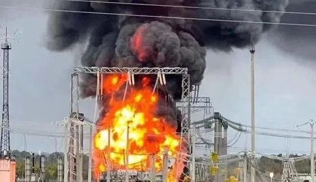
A transformer is one of the most valuable and critical assets in a power system. Despite robust design standards, no transformer is immune to the dangers of a short circuit—either internally due to winding faults or externally from system conditions. When a short circuit occurs, the transformer's thermal and mechanical limits can be exceeded in milliseconds, leading to catastrophic insulation failure, tank rupture, or even explosion. That's why transformer protection is not optional—it’s an integrated system of devices and logic designed to detect, isolate, and report faults faster than damage can occur. These protection systems must be carefully selected, tested, and calibrated according to the transformer's rating, system configuration, and fault profile.
Transformers are protected against short circuits using a combination of differential protection relays, overcurrent and earth fault protection, Buchholz relays (for oil-filled units), surge arresters, pressure relief devices, and circuit breakers. These systems rapidly detect abnormal current, voltage, or internal gas generation, and isolate the transformer from the power grid before damage escalates. Protective devices are coordinated to act within milliseconds, adhering to IEC and IEEE standards to prevent thermal or mechanical failure during faults.
Differential relays can detect both internal and external short circuits.False
Differential relays detect internal faults only; external faults are handled by overcurrent or distance relays.
The Buchholz relay protects oil-filled transformers from internal arcing and gas buildup.True
It detects gas formation and oil surge due to internal faults and trips the transformer.
Circuit breakers must trip fast enough to prevent winding deformation during a short circuit.True
Delays in breaker operation can allow mechanical damage from high fault currents.
Primary Short Circuit Protection Systems for Transformers
| Protection Device | Function |
|---|---|
| Differential Relay (87T) | Detects internal phase-to-phase and phase-to-ground faults by comparing primary and secondary current |
| Overcurrent Relay (50/51) | Trips for high fault current levels, usually for external faults |
| Ground/Earth Fault Relay (50N/51N) | Detects asymmetry indicating phase-to-ground faults |
| Buchholz Relay | Monitors internal faults via gas detection and oil movement (for oil-immersed units) |
| Surge Arrester | Protects against transient overvoltages due to lightning or switching |
| Pressure Relief Device | Vents high-pressure gas in case of internal arcing or oil breakdown |
| Temperature Relays | Trip on excessive winding or oil temperature indicating stress |
These elements are often connected to SCADA systems for remote fault indication and event logging.
Core Protection Principle: Differential Protection (87T)
Differential protection is the most critical and sensitive method for transformer short circuit protection.
| Measurement Logic | Outcome |
|---|---|
| Current In = Current Out | No internal fault, normal state |
| Current In ≠ Current Out | Internal fault, initiate trip |
Differential current:
$$
I{\text{diff}} = I{\text{primary}} - \text{CT ratio} \cdot I_{\text{secondary}}
$$
If the differential current exceeds a set threshold and is sustained for a defined time (e.g., >30 ms), the relay sends a trip signal to the circuit breaker.
Protection Coordination and Tripping Sequence
| Time (ms) | Protective Action |
|---|---|
| 0–1 ms | Fault occurs; CTs begin to sense imbalance |
| 1–10 ms | Differential relay processes data; compares phase currents |
| 10–30 ms | Relay confirms internal fault; sends trip command to breaker |
| 30–60 ms | Circuit breaker opens; transformer is isolated |
| 60–300 ms | Buchholz relay may activate if gas is forming or oil surges occur |
Speed is critical: Most mechanical damage during a short circuit happens within 50–100 ms.
Secondary and Backup Protections
| Device/Logic | Purpose |
|---|---|
| Time Overcurrent Relay | Acts as backup if differential relay fails or misses the fault |
| Restricted Earth Fault (REF) | More sensitive than general earth fault protection |
| Distance Relay (for connected lines) | Provides backup for zone-2 faults beyond transformer |
| Breaker Failure Protection | Ensures transformer is isolated even if primary breaker fails |
| Alarm and Trip Recorders | Logs sequence of events for diagnostics |
These systems work in tandem to ensure no fault goes undetected or unaddressed.
Mechanical and Thermal Fault Indicators
For oil-immersed transformers, non-electrical protective devices also provide critical safety margins:
| Device | Activation Condition | Action Taken |
|---|---|---|
| Buchholz Relay | Detects internal gas, oil surge | Trips transformer |
| Pressure Relief Valve | High-pressure surge in tank | Vents gas, sends alarm |
| Oil Level Relay | Sudden drop in conservator level | Triggers alarm or trip |
| Winding Temp Sensor | Excessive thermal rise | Initiates cooling or trip |
All signals are wired to lockout relays that can prevent re-energization until inspection is completed.
Protective Device Mapping in an Example 132/33 kV Transformer
| Protection Function | Device Code | Hardware Location | Relay Brand (Example) |
|---|---|---|---|
| Differential Protection | 87T | Main relay panel | SEL 787 / ABB RET670 |
| Buchholz Relay | — | Top of main tank (inline) | MESSKO / Qualitrol |
| Overcurrent (HV & LV) | 50/51 | Feeder panel | Siemens / Schneider |
| Earth Fault | 50N/51N | Neutral grounding system | GE Multilin / ZIV |
| Temperature Relay | 49 | Control cabinet | Rishabh / ABB |
| Pressure Relief Valve | — | Tank top or cover | Explosion-proof spring |
These form a complete protection architecture governed by IEC 60255 and IEEE C37 series standards.
Performance Chart: Fault Clearing Time vs. Transformer Damage Risk
| Fault Clearing Time | Damage Potential | Action Taken |
|---|---|---|
| <50 ms | Minimal | Protection relay fully effective |
| 50–100 ms | Medium | Mechanical stress possible |
| 100–300 ms | High | Winding displacement, insulation aging |
| >300 ms | Critical | Permanent damage, oil fire risk |
Prompt tripping preserves the mechanical and dielectric integrity of the transformer.
Conclusion
A short circuit represents a high-risk event in any electrical system, particularly for vital assets like power transformers. If not swiftly interrupted, it can cause irreversible damage to windings, insulation, and the transformer core. Comprehensive protection systems, regular maintenance, and robust design are essential to minimize risk and ensure transformer reliability under fault conditions.
FAQ
Q1: What exactly is a short circuit in a transformer?
A1: A short circuit occurs when there is an unintended low-resistance path between conductors, causing excessive current flow. In a transformer, this can happen:
Internally: between winding turns or phases
Externally: in connected cables or equipment
This sudden surge can be many times the rated current, potentially causing severe thermal and mechanical stress on the transformer components.
Q2: What are the immediate effects of a short circuit?
A2: When a short circuit occurs, it leads to:
Massive overcurrent (often 10–25 times nominal current)
Rapid heating of windings and conductors
Mechanical deformation of windings due to magnetic forces
Voltage drops or outages in the electrical system
Triggering of protection systems like circuit breakers or relays
If not cleared quickly, it can cause permanent damage or explosion.
Q3: What transformer components are most vulnerable?
A3: The components most affected by short-circuit forces include:
Windings: Can deform or burn due to heat and magnetic forces
Core insulation: May break down, causing internal arcing
Tap changers: Prone to contact welding or damage under fault currents
Bushings and terminals: Subject to flashover or thermal cracking
Repeated or high-energy short circuits shorten the transformer's lifespan significantly.
Q4: How do protection systems respond to a short circuit?
A4: Transformers are protected using:
Differential relays: Detect imbalances in current
Overcurrent relays: Trip circuits at preset limits
Buchholz relays (in oil-immersed units): Detect gas or pressure changes
Circuit breakers or fuses: Interrupt current flow within milliseconds
These systems are designed to isolate faults quickly, minimizing damage and fire risk.
Q5: Can a transformer be reused after a short circuit event?
A5: That depends on the severity. After a short circuit:
The transformer undergoes electrical and mechanical inspections
Tests include winding resistance, insulation resistance, and SFRA
Minor faults may be repairable (e.g., bushing or tap changer replacement)
Severe damage—like winding collapse or core shift—often requires full rewinding or replacement. Post-fault diagnostics are essential before re-energization.
References
Electrical4U: Short Circuit in Transformer
https://www.electrical4u.com/short-circuit-test-of-transformer/
IEEE C57.109-2018: Guide for Transformer Short Circuit Withstand
https://standards.ieee.org/standard/C57_109-2018.html
Doble Engineering: Post-Fault Diagnostic Testing
https://www.doble.com/solutions/fault-analysis-and-testing/
NREL: Transformer Reliability and Fault Tolerance
https://www.nrel.gov/docs/fy21osti/transformer-short-circuit-failure.pdf
ScienceDirect: Mechanical and Thermal Effects of Short Circuits in Transformers
https://www.sciencedirect.com/science/article/pii/S0378779619303525