Power transformers are vital for the stability and efficiency of electrical power systems. When a transformer fails, the impact can be significant—causing power outages, equipment damage, and operational disruptions. Understanding the consequences and causes of transformer failure is essential for prevention, safety, and fast recovery.
What Are the Signs of Transformer Failure?
A transformer is a critical and expensive component in power systems. When it begins to fail, the signs may be subtle—or sudden and catastrophic. Early detection of failure indicators is vital to prevent unplanned outages, avoid equipment damage, and ensure safety. Understanding the warning signs allows operators and maintenance teams to take corrective action before a complete failure occurs.
Common signs of transformer failure include excessive humming or buzzing, overheating, unusual smells, oil leakage, visible smoke, bushing discoloration, tripped protection relays, and erratic voltage output. These symptoms indicate issues such as insulation breakdown, winding faults, core overheating, oil contamination, or internal arcing.
Recognizing these early can help prevent costly blackouts or equipment explosions.
Signs of transformer failure include overheating, oil leaks, abnormal noises, and relay trips.True
These indicators signal internal or external faults that compromise the transformer's reliability and safety.
Transformers fail silently without any visible or measurable warning signs.False
Most transformer failures show physical, thermal, or electrical symptoms before a complete breakdown.
1. Audible Signs: Unusual Noises
| Symptom | Cause | Implication |
|---|---|---|
| Loud humming/buzzing | Core vibration or loose lamination | Mechanical loosening, insulation degradation |
| Crackling or sparking | Partial discharge, internal arcing | Imminent insulation failure or flashover |
| Sudden popping sound | Internal arc or fault | Major short-circuit or catastrophic failure |
New or worsening acoustic behavior is often the first symptom noticed during routine checks.
2. Thermal Signs: Overheating and Hotspots
| Symptom | Detection Method | Possible Cause |
|---|---|---|
| Surface hotspots | Infrared thermal scanning | Load imbalance, cooling failure, internal heating |
| Rising oil temperature | WTI (winding temp indicator) or OT sensor | High load, blocked radiators, oil degradation |
| Audible cooling fan failure | Manual inspection | Inactive fan leads to thermal overload |
Elevated temperature shortens insulation life and accelerates transformer aging.
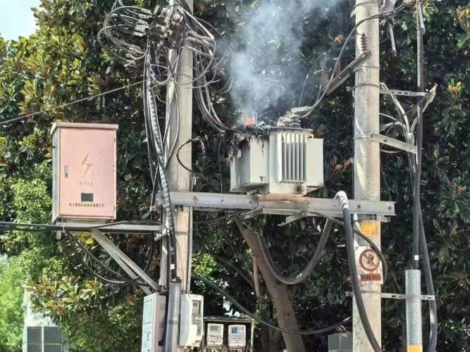
3. Visual Signs: Smoke, Leaks, and Surface Damage
| Visual Clue | Likely Fault | Consequence |
|---|---|---|
| Smoke from housing | Internal arcing or fire | Potential total failure |
| Oil leakage | Gasket damage or tank corrosion | Oil loss reduces insulation and cooling performance |
| Swollen tank or bulging | Internal gas generation (due to arcing/faults) | Pressure build-up may lead to rupture |
| Bushing discoloration | Corona discharge or thermal stress | Impending dielectric breakdown |
Any visible deformity or discoloration should trigger immediate investigation.
4. Electrical Performance Anomalies
| Indicator | Possible Root Cause | System Effect |
|---|---|---|
| Output voltage fluctuation | Tap changer failure, internal short | Equipment damage, unstable supply |
| Increased harmonics | Core saturation or partial winding failure | Poor power quality |
| Reduced insulation resistance | Moisture ingress or oil contamination | Risk of arcing or full phase-to-ground short |
| Tripped protection relay | Differential, overcurrent, or Buchholz trip | Indicates abnormal electrical conditions |
Monitor with SCADA, relays, and test kits for real-time diagnostics.
5. Chemical and Oil Indicators
| Test/Observation | Issue Indicated | Diagnostic Insight |
|---|---|---|
| Dissolved Gas Analysis (DGA) | Hydrogen, ethylene, acetylene spikes | Partial discharge, overheating, arcing |
| Moisture content in oil | Water ingress via seals or breathers | Decreases dielectric strength |
| Furan content | Cellulose insulation degradation | Confirms thermal aging or localized hot spots |
| Oil color and clarity | Darkening or sediment formation | Oxidation, contamination, internal breakdown |
Routine oil testing is a powerful predictor of internal transformer health.
Summary Table: Key Signs of Transformer Failure
| Category | Common Signs |
|---|---|
| Audible | Humming, crackling, popping |
| Thermal | High oil/winding temperatures, thermal hot spots |
| Visual | Oil leaks, smoke, deformed tank, burnt bushings |
| Electrical | Voltage instability, relay trips, insulation loss |
| Chemical/Oil | Gas generation, oil contamination, high moisture |
What Are the Common Causes of Transformer Failure?
A transformer is designed for long, reliable service—often exceeding 25 years. Yet many transformers fail prematurely due to a range of preventable causes. Understanding these failure mechanisms is critical for system reliability, maintenance planning, and asset protection. Early detection and proper preventive strategies can mean the difference between uptime and catastrophic failure.
The most common causes of transformer failure include insulation degradation, overloading, moisture ingress, poor maintenance, internal short circuits, oil contamination, mechanical vibration, lightning strikes, and aging-related wear. These issues can act alone or compound over time, leading to thermal stress, dielectric failure, and ultimately, transformer breakdown.
Each cause targets a critical part of the transformer’s structure—windings, oil, core, bushings, or the control system.
The most common causes of transformer failure include insulation breakdown, overloading, moisture, and aging-related deterioration.True
These failure mechanisms affect core components like windings, bushings, and oil, leading to system failure if not managed.
Transformer failure is usually caused by a single random event without warning.False
Most transformer failures are cumulative, with multiple stress factors building over time before failure occurs.
1. Insulation Degradation (Thermal or Electrical)
| Cause | Effect on Transformer |
|---|---|
| Excessive heat from overloads | Accelerates paper/oil breakdown |
| Partial discharges | Create localized dielectric punctures |
| Voltage surges | Stress insulation beyond its dielectric rating |
| Aging of cellulose | Reduced mechanical and dielectric strength |
Insulation breakdown is the leading cause of transformer failure, particularly in older units.
2. Overloading and Unbalanced Loads
| Cause | Consequences |
|---|---|
| Sustained operation above rating | Excessive copper losses (I²R) and heat |
| Load imbalance between phases | Uneven heating and core saturation |
| Repetitive overload cycles | Accelerated thermal aging |
Repeated overloading shortens transformer life and weakens internal components.
3. Moisture Ingress and Humidity
| Source | Damage Caused |
|---|---|
| Breather failure | Moisture enters conservator and dissolves in oil |
| Leaking seals or gaskets | Water migration into windings |
| Condensation inside tank | Reduces oil insulation strength |
Water reduces dielectric strength and increases risk of internal flashover.
4. Oil Contamination and Oxidation
| Issue | Implications |
|---|---|
| Oxidized or degraded oil | Forms sludge, reduces cooling and insulation |
| Particle contamination | Causes tracking or micro-arcing in insulation |
| Gas generation in oil | Indicates arcing or overheating |
Oil condition is a direct reflection of transformer health.
5. Electrical Faults and Short Circuits
| Fault Type | Effect |
|---|---|
| Internal winding short | Catastrophic failure or fire |
| Bushing flashover | External arcing across terminals |
| Earth faults or phase faults | Unbalance and surge inside winding system |
Most faults start small, such as insulation cracks, and grow over time.
6. Mechanical Vibration and Loosening
| Source | Failure Mechanism |
|---|---|
| Transportation shock | Displaces internal windings or braces |
| Electromagnetic forces | Loosens winding under heavy load |
| Thermal expansion/contraction | Cracks insulation or misaligns parts |
Vibration damage is common in poorly mounted or inadequately braced units.
7. Lightning and Switching Surges
| Condition | Damage Caused |
|---|---|
| Direct lightning strike | Immediate dielectric breakdown |
| Line switching surges | Impulse stress on insulation |
| Lack of surge protection | Increases risk of flashover or bushing damage |
High-voltage surges are instantaneous failure triggers if not properly mitigated.
8. Lack of Preventive Maintenance
| Neglected Task | Resulting Risk |
|---|---|
| Not monitoring oil or gas levels | Misses early signs of failure |
| Not tightening connections | Increases arcing and heat |
| Ignoring DGA reports | Misses internal arcing or overheating |
Most failures can be predicted and prevented with consistent maintenance.
9. Aging and End-of-Life Wear
| Aging Element | Degradation Outcome |
|---|---|
| Insulating paper | Brittle, cracked, no longer withstands voltage |
| Oil | Contaminated with acids, sludge |
| Seals and gaskets | Cracked, allow ingress of air/moisture |
After 20–30 years, transformers often exceed their designed mechanical or electrical limits.
Summary Table: Common Transformer Failure Causes
| Cause Category | Specific Issues |
|---|---|
| Insulation | Thermal aging, electrical breakdown, partial discharge |
| Electrical | Overload, short circuit, lightning, surges |
| Moisture | Oil-water mixture, condensation, humidity ingress |
| Oil degradation | Oxidation, contamination, sludge formation |
| Mechanical | Vibration, loosening, transport shock |
| Neglect | Missed tests, delayed repairs, uncalibrated relays |
| Aging | End-of-life deterioration of materials |
What Happens Physically Inside a Failing Transformer?
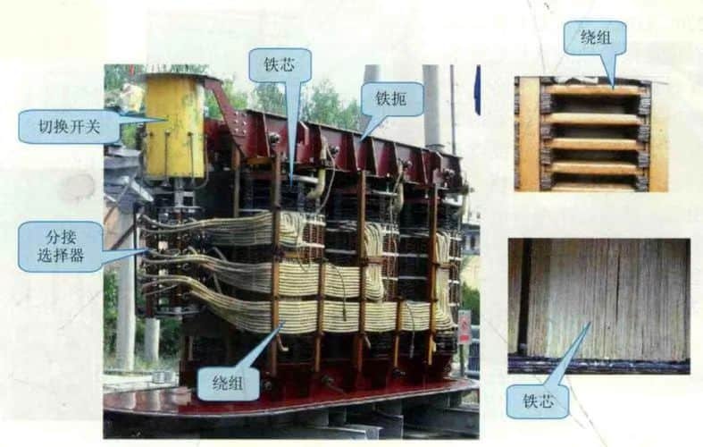
Transformers are highly engineered, precision-built devices that rely on exact spacing, insulation, and cooling to operate safely. When one begins to fail, the physical changes inside are often hidden—but severe. These internal processes can rapidly escalate from minor deterioration to complete destruction. Understanding what happens inside a failing transformer reveals why timely maintenance and monitoring are so critical.
Inside a failing transformer, physical changes include insulation breakdown, partial discharge, gas generation in the oil, local overheating, mechanical movement of windings, formation of carbonized tracking paths, moisture accumulation, and in severe cases, arcing and explosion. These processes degrade dielectric strength, distort magnetic fields, cause short circuits, and ultimately lead to catastrophic failure.
These internal changes are mostly invisible until symptoms appear externally—or damage is already done.
Inside a failing transformer, insulation breakdown, gas generation, and winding deformation occur progressively.True
Thermal and electrical stress inside the transformer weakens materials over time, leading to electrical failure and internal arcing.
Transformer failure happens without any physical changes inside the device.False
Physical degradation like insulation burning, winding collapse, and gas production is inherent to transformer failure.
1. Insulation Breakdown Begins the Chain Reaction
| Process | Physical Effect |
|---|---|
| Thermal aging of cellulose | Turns paper brittle, cracks insulation barriers |
| Electrical stress | Punctures insulation, initiates partial discharges |
| Moisture or contamination | Reduces dielectric strength, allows arcing |
As insulation fails, dielectric clearance between high-voltage components is compromised.
2. Partial Discharge and Corona Lead to Erosion
| Event | Internal Consequence |
|---|---|
| Micro-arc between winding turns | Creates localized heating and carbon paths |
| Corona near bushings or windings | Erodes insulation surfaces |
| Surface tracking | Forms conductive carbonized paths on insulation |
These early signs weaken insulation integrity, often before any external symptom is visible.
3. Gas Generation in the Oil
| Byproduct | Cause | Effect |
|---|---|---|
| Hydrogen (H₂) | Partial discharge, corona | Early warning sign |
| Acetylene (C₂H₂) | Arcing or high-energy fault | Severe internal arcing |
| Carbon monoxide/dioxide | Paper insulation overheating | Indicates deep thermal degradation |
Dissolved gas analysis (DGA) is the most reliable early-warning diagnostic for transformer failure.
4. Thermal Hot Spots Form
| Fault Area | Temperature Rise | Effect |
|---|---|---|
| Windings | 120–180 °C | Weakens copper insulation, promotes cracking |
| Core joints | Eddy current losses | Uneven heating distorts magnetic flux |
| Oil cooling path | Sludge or blockage | Impaired heat transfer, accelerated aging |
Hot spots are the primary destroyer of insulation, especially near winding ends and interlayer spaces.
5. Mechanical Deformation and Displacement
| Force Source | Physical Impact |
|---|---|
| Electromagnetic forces (short circuit) | Buckling of windings or coil shifting |
| Vibration and loose bracing | Coil abrasion, terminal misalignment |
| Repeated thermal cycling | Expansion and contraction cracks resin/oil gaps |
Structural instability causes internal short circuits and winding collapse.
6. Carbonization and Arc Tracking Paths Form
| Breakdown Zone | Observation | Consequence |
|---|---|---|
| Between winding layers | Carbonized lines, dark tracks | Conductive paths bypass insulation |
| On bushings | Brown trails or discharge rings | External flashover or surface arcing |
| In oil | Soot, blackening, gas bubbles | Loss of dielectric strength |
These faults act as conductive bridges, turning the transformer into a short circuit waiting to happen.
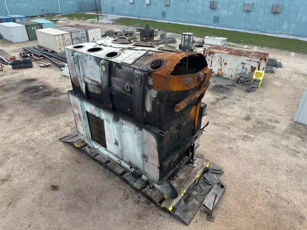
7. Final Stage: Flashover, Fire, or Explosion
| Trigger | Immediate Result |
|---|---|
| Internal arc | Superheats oil, rapid gas expansion |
| Rupture of tank | Oil sprays + arc = combustion |
| Pressure rise | Activates Buchholz relay or pressure relief device |
These final events result in total transformer destruction, potential grid blackouts, and safety hazards.
Summary Table: Physical Changes Inside a Failing Transformer
| Failure Mechanism | Internal Physical Process |
|---|---|
| Insulation aging | Cracking, shrinking, loss of dielectric integrity |
| Partial discharge | Formation of voids, carbonized tracking |
| Overheating | Oil oxidation, sludge, thermal expansion |
| Winding movement | Coil displacement, inter-turn short |
| Gas generation | Hydrogen, acetylene bubbles in oil |
| Arcing | Burned insulation, core damage, magnetic distortion |
What Are the System-Wide Effects of Transformer Failure?
When a transformer fails, the consequences go far beyond a single piece of equipment. It can initiate a ripple effect throughout the entire electrical network, affecting load balance, voltage regulation, grid reliability, and even public safety. Depending on its role in the system, a failed transformer can interrupt critical infrastructure, cause cascading outages, or damage adjacent components. The bigger the transformer, the bigger the impact.
Transformer failure can cause widespread power outages, system frequency imbalances, voltage collapse, overloading of adjacent transformers, disruption of industrial and critical services, fire or explosion risk, and high economic losses. It often triggers protective relay operations, backup system activation, and can initiate cascading grid failures if not contained.
The failure of one transformer—especially at a substation or generation point—can impact an entire city, region, or industrial zone.
Transformer failure can lead to cascading outages, overloading of nearby equipment, and grid instability.True
Transformers are central to energy flow; their failure disrupts voltage balance and system topology, creating widespread effects.
Transformer failure only affects the equipment itself and has no wider impact.False
Transformers are integral to power networks; their failure affects grid stability, reliability, and system-wide safety.
1. Immediate Local Effects
| Impact | System Response |
|---|---|
| Sudden loss of power transfer | Load dropout, local blackout |
| Protection relay activation | Trip of upstream/downstream circuit breakers |
| Thermal/electrical stress nearby | Adjacent cables and components may be damaged |
| Explosion or fire risk | Site evacuation, emergency response needed |
Failure at the point of connection can disconnect entire substations or feeders instantly.
2. Load Redistribution and Overloading
| Event | System-Wide Result |
|---|---|
| Load shifts to parallel transformers | Remaining units experience overload |
| Overcurrent protection activates | Other feeders or transformers may trip |
| Thermal stress increases | Speeds up aging and failure risk in nearby equipment |
Transformers are often configured in parallel or N-1 configurations, so failure of one puts immediate pressure on the rest.
3. Voltage Instability and Collapse
| Cause | System Effect |
|---|---|
| Loss of voltage control | Reactive power deficiency and voltage sag |
| Undervoltage on long feeders | Lights dimming, motors stalling |
| Inability to regulate local voltages | Risks sensitive equipment and customer complaints |
Large power transformers play a key role in voltage regulation and tap adjustment.
4. Frequency and Grid Stability Issues
| Scenario | Grid Reaction |
|---|---|
| Major generation transformer failure | Load-generation mismatch → frequency drop |
| Sudden load loss | Frequency spike → turbine speed-up, need for load shedding |
| Interconnection disturbance | Islanding risk or blackout if not handled quickly |
Transformer failure at a generation intertie can destabilize an entire region.
5. Impact on Critical Infrastructure
| Affected Sector | Consequences |
|---|---|
| Hospitals and emergency services | Disruption unless backup generators start flawlessly |
| Data centers and telecoms | Possible downtime, data loss, or hardware failure |
| Water/sewage plants | Loss of pumping, overflow risk, sanitation failure |
| Airports, metros, railways | Outages cause transportation gridlock |
Transformers power the backbone of public safety and economic stability.
6. Economic and Operational Losses
| Cost Element | Example Consequence |
|---|---|
| Equipment damage | Burned switchgear, relay failures, damaged cabling |
| Lost revenue | Manufacturing downtime, service unavailability |
| Utility fines | Penalties for SLA violations or blackout occurrences |
| Replacement delays | Power transformers take months to design and commission |
A single transformer failure can lead to millions in economic loss and long-term recovery delays.
7. Cascading Failure Risk in Interconnected Grids
| Trigger Event | Grid-Wide Escalation |
|---|---|
| Large transformer failure | Overloads nearby units → additional failures |
| No fast load shedding | System frequency collapse → rolling blackouts |
| Delayed operator response | Entire grid segment destabilizes |
Grid resilience depends on real-time response, redundant design, and condition monitoring.
Summary Table: System-Wide Effects of Transformer Failure
| Failure Impact Area | Consequence |
|---|---|
| Local load supply | Blackout or brownout |
| Adjacent transformers | Overloading, thermal stress, risk of cascading failure |
| Voltage and frequency control | Imbalance, instability, under/over-voltage |
| Critical infrastructure | Service disruption in hospitals, data, transit |
| Economy and operations | Lost production, fines, long lead times |
| Grid integrity | Protection trips, blackouts, wide-area instability |
How Is a Failed Transformer Diagnosed and Handled?
A transformer failure can cause significant disruption—so determining the cause, evaluating the damage, and executing a recovery plan must be done efficiently and accurately. Whether the failure is partial, progressive, or catastrophic, utilities and plant operators rely on a combination of field inspections, electrical tests, oil diagnostics, and forensic analysis to pinpoint the issue and guide the next steps: repair, refurbishment, or replacement.
To diagnose and handle a failed transformer, engineers follow a multi-step process involving physical inspection, oil sampling for dissolved gas analysis (DGA), insulation resistance and winding tests, thermal imaging, and protective relay event logs. Once the failure is diagnosed, the transformer may be de-energized, isolated, and repaired on-site—or removed for factory refurbishment or replacement.
A prompt, systematic approach minimizes downtime, safety risks, and financial loss.
Transformer failure is diagnosed using tools such as DGA, thermal scanning, insulation testing, and relay analysis.True
These diagnostic methods help identify root causes like insulation breakdown, overheating, or electrical faults.
When a transformer fails, it must always be replaced immediately without investigation.False
Transformers are first diagnosed to determine whether repair or refurbishment is possible before replacement is considered.
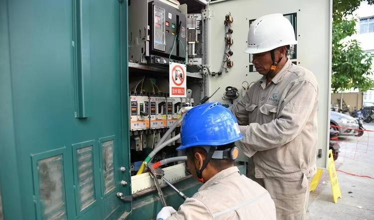
1. Initial Response: Safety First and Isolation
| Action | Purpose |
|---|---|
| Trip the transformer circuit | Prevents further damage or hazards |
| Secure the perimeter | Protects workers and public from electrical/fire risk |
| Notify grid or plant control | Allows for system reconfiguration or rerouting |
After failure, transformers are isolated both electrically and physically.
2. Visual and Thermal Inspection
| Inspection Type | What It Reveals |
|---|---|
| External damage check | Oil leaks, smoke traces, tank deformation |
| Bushing and terminal exam | Cracks, burn marks, corona evidence |
| Infrared thermal scan | Hot spots indicating winding or core heating |
Immediate physical signs often indicate the failure zone or severity.
3. Oil Sampling and Dissolved Gas Analysis (DGA)
| Gas Type Detected | Indicated Fault Type |
|---|---|
| Hydrogen (H₂) | Partial discharge |
| Acetylene (C₂H₂) | Arcing or high-energy discharges |
| Methane + Ethane | Thermal overheating |
| Carbon oxides | Insulation paper degradation |
DGA provides a chemical fingerprint of what’s occurring inside the transformer.
4. Electrical Testing Procedures
| Test Type | Purpose |
|---|---|
| Insulation Resistance Test | Measures health of winding-to-ground insulation |
| Power Factor Test (tan δ) | Evaluates dielectric aging and moisture in insulation |
| Turns Ratio Test (TTR) | Detects winding deformation or open circuits |
| Sweep Frequency Response | Identifies mechanical shifts in windings |
These tests help determine whether repair is viable or if the core is compromised.
5. Protection Relay and SCADA Data Review
| Data Source | Insight Gained |
|---|---|
| Differential relay logs | Confirms internal short circuits |
| Buchholz relay activation | Indicates gas formation or oil movement |
| SCADA trends | Reveals pre-failure temperature or current spikes |
Event logs give critical context for when and how the failure occurred.
6. Decision-Making: Repair vs. Replacement
| Condition | Recommended Action |
|---|---|
| Minor oil contamination | Flush and refill with treated oil |
| Bushing damage only | Replace bushings, test insulation |
| Localized winding fault | Rewind affected coil, re-test |
| Core deformation or tank rupture | Remove from service, replace or fully refurbish |
Transformers are not always scrapped—partial repairs are often feasible.
7. Handling Logistics: On-Site or Factory Repair
| Approach | Best For | Limitations |
|---|---|---|
| On-site repair | Minor failures, bushing, tap changer, oil service | Limited access to deep internal components |
| Factory refurbishment | Rewinding, core rebuild, full requalification | Longer lead time and transport coordination |
| Complete replacement | Aged unit or extensive failure | Expensive and time-intensive |
Many utilities keep strategic spares or mobile transformers to reduce downtime.
8. Post-Restoration Testing and Commissioning
| Final Checks | Ensures |
|---|---|
| Voltage withstand tests | Unit can handle rated voltages safely |
| Ratio and impedance testing | Restored electrical symmetry and functionality |
| Oil DGA after re-energization | No abnormal gas generation |
| Thermographic scanning | Stable operation under load |
After repair, the transformer must be re-certified before being returned to service.
Summary Table: Diagnosing and Handling a Failed Transformer
| Stage | Activity | Purpose |
|---|---|---|
| Initial isolation | De-energize and secure site | Safety and fault containment |
| Visual/thermal inspection | Check for external and internal symptoms | Quick assessment |
| Oil and gas testing | Analyze internal chemical state | Fault type identification |
| Electrical tests | Evaluate insulation and winding integrity | Repair feasibility |
| Data analysis | Relay/SCADA event correlation | Understand failure timeline |
| Decision and action | Repair, rewind, or replace | Restore system function |
| Post-repair testing | Recommission with full diagnostics | Safe return to operation |
What Measures Can Prevent Transformer Failure?
Transformers are built to last—but only when operated and maintained correctly. Many transformer failures are not due to sudden events, but progressive, preventable conditions like insulation aging, oil contamination, or missed warning signs. To ensure reliability, prevent costly downtime, and extend service life, a combination of design best practices, real-time monitoring, and preventive maintenance is essential.
Preventing transformer failure requires a proactive strategy that includes regular dissolved gas analysis (DGA), thermographic inspections, insulation resistance testing, oil quality monitoring, proper loading practices, surge protection, routine maintenance, and ensuring environmental safeguards. These measures identify degradation early and reduce stress on key transformer components.
By addressing potential failure mechanisms before they escalate, transformer reliability is maximized and service life extended.
Preventive maintenance and monitoring can significantly reduce the risk of transformer failure.True
Early detection of internal faults, oil degradation, and insulation weakening allows corrective actions before a failure occurs.
Transformer failure cannot be prevented and always occurs without warning.False
Most transformer failures give early symptoms and are preventable through diagnostics and condition-based maintenance.
1. Routine Dissolved Gas Analysis (DGA)
| What It Does | Why It Matters |
|---|---|
| Detects gases from insulation/oil breakdown | Early warning of overheating, arcing, or discharge |
| Identifies fault type using gas ratios | Confirms partial discharge vs. high-energy arcing |
| Monitors degradation trends over time | Enables predictive maintenance |
DGA is the gold standard for internal fault detection in oil-filled transformers.
2. Infrared Thermographic Inspections
| Purpose | Failure Prevented |
|---|---|
| Identifies abnormal hot spots | Loose connections, overload, winding imbalance |
| Detects cooling system failure | Radiator blockage, fan/pump malfunction |
| Maps temperature gradients | Reveals aging insulation or core heating |
Thermal anomalies often appear before electrical faults develop.
3. Oil Quality and Moisture Monitoring
| Parameter Measured | Risk Reduced |
|---|---|
| Dielectric strength | Prevents insulation flashover |
| Moisture content | Avoids paper deterioration and arcing |
| Acidity and sludge levels | Indicates oxidation and oil aging |
Clean, dry, stable oil is crucial to transformer health.
4. Regular Electrical Testing
| Test Type | Failure Prevented |
|---|---|
| Insulation resistance (IR) | Detects moisture and insulation weakness |
| Polarization Index (PI) | Evaluates insulation aging |
| Power factor (tan δ) | Identifies contamination or partial discharge |
| Turns ratio (TTR) | Confirms winding health |
Annual or biannual testing keeps insulation systems under control.
5. Load Management and Thermal Monitoring
| Practice | Outcome |
|---|---|
| Avoiding sustained overload | Limits heat buildup and copper stress |
| Balanced phase loading | Prevents uneven heating and core saturation |
| Monitoring load profile | Informs tap settings and cooling needs |
Overloading shortens life—smart load management extends it.
6. Surge and Overvoltage Protection
| Device | Function |
|---|---|
| Surge arresters | Protect against lightning and switching surges |
| Shielded bushings | Prevent flashovers |
| Grounding systems | Dissipate transient energy safely |
External surges are instant transformers killers without protection.
7. Environmental and Physical Safeguards
| Control | Failure Prevented |
|---|---|
| Temperature/humidity control | Avoids condensation and insulation degradation |
| Oil level and pressure checks | Prevents tank rupture or vacuum collapse |
| Secure fencing and drainage | Protects from rodents, water, and physical damage |
Environmental exposure is a silent contributor to aging and failure.
8. Protection Relay Calibration and Review
| System | Risk Avoided |
|---|---|
| Differential relays | Detect winding short circuits quickly |
| Overcurrent and Buchholz | Signal overload or gas accumulation |
| SCADA alarms | Enable real-time intervention |
Well-tuned protection relays are critical to containing fault impact.
Summary Table: Measures That Prevent Transformer Failure
| Preventive Measure | Failure Mode Mitigated |
|---|---|
| DGA and oil testing | Arcing, overheating, insulation degradation |
| Infrared thermography | Loose connections, hot spots, cooling failure |
| Insulation testing | Aging or contaminated insulation |
| Proper load control | Thermal stress, core distortion |
| Surge protection | External faults, bushing flashover |
| Maintenance scheduling | Catch wear-and-tear before breakdown |
| Relay system calibration | Detects and reacts to faults instantly |
Conclusion
When a power transformer fails, it can lead to severe consequences—from localized outages to wide-area blackouts. The failure might result from insulation breakdown, overloading, oil contamination, or external factors like lightning. Recognizing early warning signs such as abnormal noise, overheating, or oil leaks is critical. Regular maintenance, proper protection systems, and intelligent monitoring can significantly reduce the risk of failure, ensuring power system reliability and safety.
FAQ
Q1: What happens when a power transformer fails?
A1: When a power transformer fails, it often results in:
Sudden power outages for connected areas
Voltage instability across the grid
Damage to nearby equipment due to electrical surges
Potential fire, explosion, or oil leakage if the fault is severe
Such failures can disrupt industrial operations, cause blackouts, and require immediate emergency response.
Q2: What causes a power transformer to fail?
A2: Common causes include:
Insulation breakdown
Overloading or overheating
Internal short circuits
External faults (lightning, moisture, rodents)
Aging components or poor maintenance
These issues can lead to catastrophic mechanical or electrical failure.
Q3: How does a transformer failure affect the power grid?
A3: A failure can:
Trip protective relays, isolating the transformer from the network
Trigger load transfers to neighboring transformers
Cause system-wide voltage drops or blackouts
Delay energy distribution until repairs or replacements are completed
In high-demand regions, it may also affect grid stability and supply continuity.
Q4: What are the warning signs before a transformer fails?
A4: Indicators of impending failure include:
Unusual noise (buzzing or humming)
Rising oil or winding temperatures
Gas buildup in oil (detected via DGA)
Leaking oil or damaged bushings
Frequent tripping or alarms from monitoring systems
Q5: What is done after a transformer failure?
A5: Utility teams typically:
Isolate the faulted transformer for safety
Inspect and assess damage
Dispatch a mobile substation or reroute power if available
Repair or replace the transformer
Re-energize and test the system before full restoration
Replacement may take hours to weeks, depending on transformer size and availability.
References
"What Happens When a Power Transformer Fails?" – https://www.transformertech.com/transformer-failure-response
"Common Causes and Effects of Transformer Failure" – https://www.electrical4u.com/power-transformer-failure-causes
"Managing Power Transformer Failures in Grids" – https://www.powermag.com/transformer-breakdown-guide
"Energy Central: Impacts of Transformer Failure on Utilities" – https://www.energycentral.com/c/ee/transformer-grid-impact
"Smart Grid News: Transformer Outages and Restoration" – https://www.smartgridnews.com/transformer-failure-response
"ScienceDirect: Early Detection and Prevention of Transformer Failure" – https://www.sciencedirect.com/power-transformer-failure-signs
"ResearchGate: Analysis of Major Transformer Failures" – https://www.researchgate.net/transformer-failure-analysis
"PowerGrid: Response Strategy for Power Transformer Damage" – https://www.powergrid.com/emergency-transformer-repair