Transformers are critical components in the power grid, ensuring stable voltage transmission and distribution. However, when a transformer "blows," it signifies a sudden and often dangerous failure. Understanding what happens during such an event helps power professionals, engineers, and the public assess risks and ensure system reliability.
What Does It Mean When a Transformer Blows?
Transformers are silent workhorses of the power system, but when something goes wrong—it can go very wrong. A loud bang, a sudden power outage, or smoke rising from a pole-mounted unit often signals what many describe as “a transformer blowing.” This isn’t just a mechanical failure—it’s usually an electrical or thermal event that leads to catastrophic internal damage, and it can affect hundreds or even thousands of customers. But what does “blowing” actually mean in technical terms?
When a transformer blows, it typically means a sudden and catastrophic failure has occurred due to internal arcing, insulation breakdown, overloading, or a short circuit. This causes an explosive release of energy, often resulting in noise, fire, smoke, or rupturing of the tank. Common causes include lightning strikes, equipment aging, overvoltage, thermal stress, or a severe fault in the connected system. The transformer loses its ability to safely regulate voltage, and protective relays immediately trip the circuit to prevent wider grid damage.
This failure can be dangerous, costly, and disruptive—and always requires professional investigation and replacement or repair.
A transformer ‘blowing’ refers to a catastrophic internal failure, often due to arcing, short circuits, or insulation failure.True
This event typically results in a loud noise, loss of function, and visible smoke or fire due to sudden energy discharge.
A blown transformer simply means it needs to be refilled with oil or reset.False
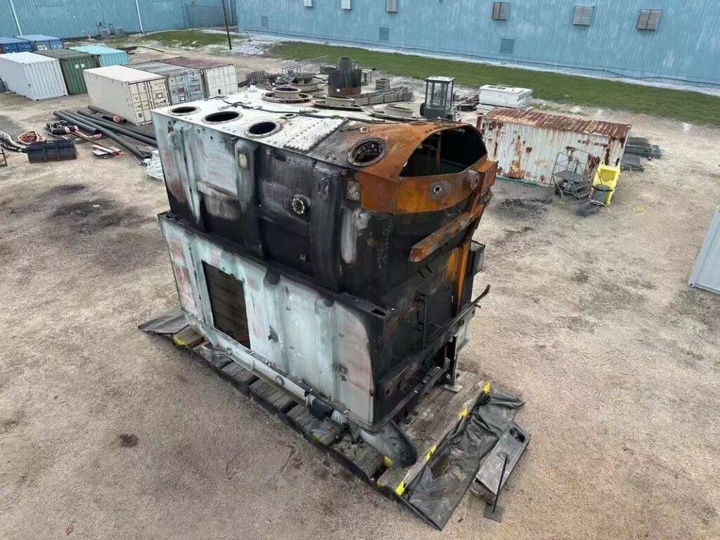
Once a transformer experiences a blowout, it often has irreversible internal damage that requires replacement or complete rebuild.
1. What Happens Physically When a Transformer Blows?
| Event Type | Physical Reaction |
|---|---|
| Internal Short Circuit | Arcing between windings or to ground, rapid heat rise |
| Dielectric Breakdown | Insulation failure, often due to moisture or contamination |
| Thermal Overload | Oil or winding temperature exceeds safe limits, leads to vaporization |
| Overvoltage Surge | Lightning or switching causes flashover, damaging bushings or insulation |
| Gas Generation | Dissolved gas increases pressure, possibly triggering rupture or fire |
When a transformer “blows,” it’s not an explosion in the explosive sense, but an electrical energy discharge that ruptures internal components.
2. Symptoms and Signs of a Blown Transformer
| Indicator | What It Means |
|---|---|
| Loud Boom or Bang | Internal arc or sudden dielectric breakdown |
| Smoke or Flames | Oil ignition or carbonized insulation burning |
| Loss of Power | Transformer opens circuit; protection system disconnects load |
| Visible Oil Leak or Tank Bulge | Pressure relief failure or thermal expansion |
| Burnt Smell or Soot Marks | Arcing damage inside core or winding area |
Field crews and protection systems detect these signs immediately and isolate the transformer from the grid.
3. Common Causes of Transformer Blowouts
| Cause | Explanation |
|---|---|
| Lightning Strike | External overvoltage causes flashover in winding or bushings |
| Aging Insulation | Paper or oil insulation degrades over decades |
| Overloading | Continuous high current exceeds thermal limit |
| Oil Contamination | Moisture or particles reduce dielectric strength |
| Manufacturing Defects | Poor bushing design, winding misalignment, or core vibration issues |
Many failures are preventable through periodic testing and diagnostics (e.g., DGA, thermography, bushing analysis).
4. Protective Systems That React When a Transformer Blows
| Protection Device | Function During Fault |
|---|---|
| Differential Relay (87T) | Trips circuit in case of internal fault |
| Buchholz Relay | Detects gas generation or oil movement from internal arcing |
| Pressure Relief Device (PRD) | Vents excess pressure to avoid tank rupture |
| Circuit Breaker | Disconnects transformer from grid automatically |
| Surge Arresters | Absorb lightning or switching surges before they reach core |
These systems limit the damage and prevent the fault from spreading to other grid components.
5. What to Do After a Transformer Blowout
| Action | Purpose |
|---|---|
| Isolate the Unit | Prevent further electrical risk or fire spread |
| Visual Inspection | Identify burn marks, ruptures, or oil leaks |
| Electrical Testing | Confirm winding, core, and insulation damage |
| Replace or Repair | Based on fault severity and equipment age |
| File Grid Incident Report | Analyze and prevent future recurrence |
In critical infrastructure, backup transformers are switched in within hours or minutes.
Real-World Case Example
- Location: 220/66 kV substation, Europe
- Incident: Loud bang, followed by fire at HV bushing
- Root Cause: Lightning surge + defective bushing insulation
- Damage: Tank breach, OLTC destroyed, complete unit loss
- Response: Isolated within 0.3s, replaced within 72 hours
- Impact: Power diverted through alternate 220 kV feeder, no prolonged blackout
The protection system limited the blackout and localized the fault, demonstrating how design and maintenance matter.
What Are the Common Causes of Transformer Failure?
Transformers are among the most durable assets in power systems, often expected to operate for 30 to 50 years. However, when a transformer fails, the consequences can be severe: equipment destruction, unplanned outages, grid instability, and costly repairs. While catastrophic blowouts get the most attention, most transformer failures are preventable—and often caused by gradual deterioration or environmental stress. Understanding these causes is essential for engineers, operators, and asset managers aiming to ensure long-term grid reliability.
The most common causes of transformer failure include insulation breakdown, oil contamination, overloading, moisture ingress, bushing failure, short circuits, aging, corrosion, poor maintenance, manufacturing defects, and lightning or switching surges. These issues can degrade internal components over time or trigger sudden catastrophic failures. Diagnosing and mitigating these causes through condition monitoring, testing, and preventive maintenance is essential for transformer longevity.
Proactive management of these risks helps avoid forced outages, repair costs, and system downtime.
Insulation degradation, oil contamination, overloading, and electrical surges are leading causes of transformer failure.True
These issues compromise dielectric strength, generate internal arcing, and increase thermal stress, often resulting in irreversible damage.
Transformer failure is always sudden and impossible to predict.False
Most failures result from gradual degradation that can be monitored through diagnostic testing and maintenance.
1. Insulation Breakdown
| Cause | Impact |
|---|---|
| Aging of paper insulation | Reduced dielectric strength, higher risk of partial discharge |
| Thermal overloading | Accelerates cellulose degradation |
| Electrical stress | Causes insulation cracks and punctures |
| Oil oxidation | Produces acids that degrade solid insulation |
Insulation failure is the #1 cause of transformer malfunction, accounting for over 30% of failures globally.
2. Oil Contamination or Deterioration
| Issue | Effect on Transformer |
|---|---|
| Moisture contamination | Reduces dielectric strength of oil and paper |
| Oxidation and acid buildup | Leads to sludge formation and corrosion |
| Particle contamination | Triggers partial discharge and accelerates failure |
| Gas generation | Indicates internal arcing or thermal hotspots |
Dissolved Gas Analysis (DGA) is the most effective tool to detect these conditions early.
3. Electrical Overloading
| Type | Result |
|---|---|
| Continuous overloading | Causes excessive heat and accelerated insulation aging |
| Short-term peak overloads | Triggers winding hot spots and stress on cooling systems |
| Under-rated design | Leads to frequent thermal excursions and reduced life |
Even 10% overloading over time can halve transformer lifespan.
4. Moisture Ingress
| Source | Effect |
|---|---|
| Poor gasket sealing | Allows ambient humidity into the tank |
| Condensation in idle units | Raises moisture in insulation paper |
| Breather failure | Silica gel saturation allows humid air into conservator |
Water in insulation reduces dielectric strength dramatically—just 3% moisture can reduce life by 50%.
5. Bushing Failures
| Defect | Consequence |
|---|---|
| Oil leaks or moisture ingress | Loss of insulation and possible flashover |
| Capacitance change | Indicates internal breakdown or tracking |
| Overvoltage or poor grounding | Causes catastrophic blowout at high voltage |
Bushings account for 10–20% of transformer failures, often accompanied by explosive noise and oil ejection.
6. Lightning or Switching Surges
| Source | Failure Mode |
|---|---|
| Direct lightning strike | Causes flashover across windings or bushings |
| Line switching or faults | Generates transient overvoltages |
| Inadequate surge protection | Fails to suppress high-energy pulses |
Surge arresters are critical—failure to maintain them increases risk of HV insulation rupture.
7. Poor Cooling and Overheating
| Cooling System Issue | Impact on Operation |
|---|---|
| Radiator clogging | Limits heat exchange, increases winding temperature |
| Fan/pump failure (OFAF) | Reduces active cooling efficiency |
| Ambient heat load | Stresses oil system in summer or desert conditions |
Every 6°C rise above design temperature halves insulation life—making cooling efficiency vital.
8. Aging and End-of-Life Deterioration
| Typical Signs | Associated Risks |
|---|---|
| Increased DGA gases | Indicates internal fault development |
| High moisture in insulation | Sign of paper aging |
| Increased PD activity | Predicts failure of winding or core insulation |
Most failures occur during the last 10–15% of expected transformer lifespan.
9. Manufacturing or Design Defects
| Problem Type | Potential Failure |
|---|---|
| Winding displacement | Mechanical failure under short circuit |
| Inadequate insulation gaps | Flashover risk under transient surge |
| Core lamination defects | Localized heating or core grounding issues |
Design-related failures often occur within the first 5 years, called “infant mortality.”
10. Lack of Maintenance or Testing
| Neglected Practice | Risk Introduced |
|---|---|
| No DGA monitoring | Undetected gas buildup, late fault diagnosis |
| Skipped oil filtration | Contaminants accelerate insulation breakdown |
| Ignoring cooling system | Hidden overheating, leads to coil failure |
| No periodic electrical testing | Missed early insulation or winding issues |
Routine testing and monitoring extend life, reduce outage risk, and prevent catastrophic failure.
Summary Table: Common Transformer Failure Causes
| Cause | Failure Risk | Detection Method |
|---|---|---|
| Insulation aging | High (most common) | DGA, Tan δ, insulation resistance |
| Oil degradation | High | DGA, oil quality test |
| Overloading | Medium to high | Load profiling, hotspot analysis |
| Bushing failure | High impact, localized | Capacitance test, IR scan |
| Surge/lightning | High (if unprotected) | Surge arrester monitoring |
| Cooling failure | Medium | Fan/pump status, temp sensors |
| Moisture ingress | High | Oil moisture test, breather check |
| Aging | Progressive, high risk | Comprehensive condition assessment |
| Factory defect | Low frequency, high severity | Early testing, design audit |
What Are the Immediate Visual and Audible Signs of a Blown Transformer?
A transformer failure—often described as a “blowout”—can happen suddenly and with alarming force. Whether in a quiet neighborhood or a busy industrial substation, these incidents often generate intense visual and audible cues. Identifying these signs quickly is critical for safety, fault diagnosis, and grid protection. These immediate symptoms often reveal that the internal components—windings, insulation, or oil—have suffered catastrophic damage due to overheating, electrical arcing, or short circuits.
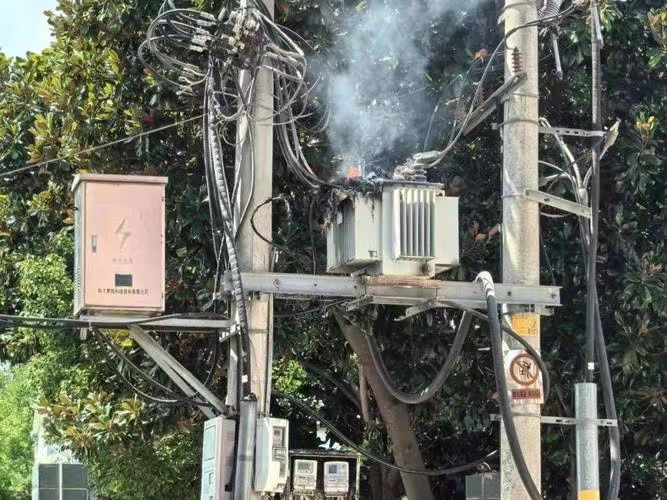
The immediate visual and audible signs of a blown transformer include a loud explosive bang or cracking sound, bright flashes or sparks, plumes of smoke, visible flames or fire near bushings or vents, leaking or spraying insulating oil, and discoloration or deformation of the transformer tank. These signs indicate a severe internal failure, often triggered by insulation breakdown, arcing, or a fault current. The transformer typically shuts down instantly, and power to surrounding areas is lost.
These warning signs should never be ignored—they demand immediate safety measures and technical response.
Loud bangs, sparks, smoke, and fire are common signs of a blown transformer.True
These are caused by internal arcing, insulation failure, and the sudden release of energy during a major electrical fault.
There are usually no signs when a transformer blows; it just quietly stops working.False
Transformer blowouts are violent events and produce clear auditory and visual symptoms due to the nature of high-voltage failure.
1. Audible Warning Signs
| Sound | Description | Cause |
|---|---|---|
| Loud Boom / Explosion | Sudden, deep, cannon-like sound | Instant internal short circuit or arc flash |
| Crackling / Sparking | Rapid electrical popping or fizzing | Discharge across insulation or windings |
| Hissing or Gurgling | Steady sound post-failure | Escaping gas or boiling oil inside tank |
| High-pitched whine | Rising electrical pitch before failure | Core saturation, overexcitation or arcing |
These sounds are high-energy discharge indicators and should prompt immediate isolation of the affected area.
2. Visual Warning Signs
| Visual Indicator | Meaning | What to Look For |
|---|---|---|
| Flash or Spark | Electrical arc or bushing breakdown | Visible at night or dusk |
| Plume of Smoke | Insulation or oil combustion | White, gray, or black smoke |
| Fire or Flame | Oil ignition due to arcing | Appears near bushings, vents, or tank walls |
| Oil Leak or Spray | Tank rupture or relief device triggered | Oil stains on ground or cabinet |
| Deformed or Bulged Tank | Internal overpressure | Tank swelling or open vent cover |
| Burn Marks or Charring | Evidence of internal arc flash or bushing fault | Blackening near terminals or casing |
At night, bright flashes may precede the failure; in daylight, smoke and oil spray may be more visible than flames.
3. Immediate System Responses
| System Event | Description | Cause |
|---|---|---|
| Power Outage | Complete loss of supply to affected area | Circuit breaker or relay tripped |
| Relay Trip / Alarm | Protective system isolates the fault | Differential relay, Buchholz relay, or PRD |
| SCADA Alert | Remote system reports abnormal condition | Gas generation or thermal surge detected |
| Arrester Flashover | Visual flash near surge arrester | Overvoltage due to lightning or switching |
Grid protection schemes typically isolate the fault within milliseconds, but physical signs persist for minutes.
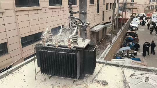
4. Case Snapshot: Pole-Mounted Transformer Failure
- Location: Residential street, 11 kV distribution
- Time: 6:50 PM (peak load)
- Audible Cue: Loud bang, followed by popping and hissing
- Visual Cue: Bright arc flash, smoke column rising, oil dripping from casing
- Impact: 160 homes lost power; local fire brigade called
- Diagnosis: Lightning surge + aged bushing failure
Quick reaction prevented escalation to adjacent feeders and highlighted the importance of surge arresters and bushing condition monitoring.
5. Post-Failure Indicators
| Residual Sign | Implication |
|---|---|
| Burnt or ruptured bushings | Failure at connection point |
| Soot around vents | Oil ignition and discharge path |
| Collapsed or leaning pole | Explosion pressure deformed structure |
| PRD (Pressure Relief Device) triggered | Overpressure venting occurred |
These signs guide investigation, root cause analysis, and insurance claims.
What Are the Safety Risks and Environmental Impacts of Transformer Failures?
When a power transformer fails—especially suddenly—it doesn’t just disrupt electricity. It can also cause fires, explosions, hazardous chemical releases, and physical harm to workers and the surrounding environment. Transformers contain flammable insulating oil, operate at lethal voltages, and are often situated in populated or ecologically sensitive areas. Understanding the safety risks and environmental consequences is critical for utilities, industries, municipalities, and emergency responders.
Transformer failures present significant safety risks including fire, explosion, electrocution, toxic gas exposure, and falling debris. Environmentally, they can lead to soil and water contamination from leaking transformer oil (which may be PCB-based in older units), harm to local wildlife, air pollution from smoke and soot, and long-term ecological damage if spills are not contained. These risks can affect people, infrastructure, and ecosystems, especially if preventive systems and emergency protocols are inadequate.
The consequences go beyond outages—they can trigger serious public health, legal, and environmental liabilities.
Transformer failures can cause fire, oil leakage, electrocution, and environmental pollution.True
High voltage, flammable oil, and toxic byproducts create real safety and ecological hazards during failure events.
Transformer failures are only electrical issues and pose no safety or environmental threats.False
Transformers can cause explosions, fires, oil spills, and chemical exposure, requiring strict handling and mitigation protocols.
1. Safety Risks to Humans and Infrastructure
| Risk Type | Description | Impact |
|---|---|---|
| Explosion and Fire | High-energy arc faults ignite oil, resulting in fireballs | Burns, injury, property damage |
| Electrocution | Live parts exposed during or after failure | Fatal voltage contact for workers or bystanders |
| Falling Equipment | Structural collapse of poles or tanks during blowout | Physical injuries, downed lines |
| Toxic Gas Release | Combustion of oil produces CO, dioxins, and other toxins | Respiratory hazard to nearby personnel |
| Flashover Radiation | Arc flashes emit thermal and optical radiation | Eye injury, skin burns from UV and heat |
These dangers demand restricted access, arc-flash rated PPE, and live-line clearance protocols during response.
2. Fire and Explosion Hazards
| Cause | Effect |
|---|---|
| Internal Arcing | Ignites vaporized oil |
| Pressure Build-up | Can rupture tank violently |
| Faulty Bushings or OLTC | Short circuits lead to ignition sources |
| Oil Contamination | Lowers flash point, increasing fire likelihood |
Fires in substations can spread to adjacent transformers, control rooms, or buildings, requiring rapid suppression.
3. Environmental Impact of Oil Spills
| Contaminant | Source | Environmental Risk |
|---|---|---|
| Mineral Oil | Most modern transformers | Toxic to aquatic life, persistent in soil |
| PCBs (Polychlorinated Biphenyls) | Found in older transformers pre-1980s | Highly toxic, bioaccumulative, banned in many countries |
| Dissolved Metals | Breakdown of internal windings | Heavy metal contamination in water/soil |
| Sludge and Acid Byproducts | Oil degradation residue | Alters pH in soil, affects vegetation growth |
A single medium transformer can contain hundreds to thousands of liters of oil, which may seep into groundwater if not contained.
4. Air and Water Pollution
| Pollutant | Emission Source | Effect |
|---|---|---|
| Smoke, soot | Burning oil and insulation | Respiratory irritation, air quality degradation |
| Hydrocarbon vapor | Oil leaks, tank venting | Ozone precursor and workplace hazard |
| Runoff contamination | Rain spreads leaked oil to waterways | Ecotoxicity to aquatic ecosystems |
Surface water protection and soil barriers are essential near transformer yards to limit spread.
5. Wildlife and Ecosystem Damage
| Hazard | Affected Species or Systems | Long-Term Consequences |
|---|---|---|
| Oil film on water | Fish, amphibians, aquatic insects | Suffocation, toxin absorption |
| Soil contamination | Plants, invertebrates | Reproductive failure, bioaccumulation |
| Groundwater leaching | Drinking water sources | Human and animal health risks |
| Noise and fire disturbance | Birds, small mammals | Habitat disruption and displacement |
Spills in rural or undeveloped areas can impact entire ecosystems and food chains if not remediated.
6. Emergency and Regulatory Response
| Response Activity | Purpose |
|---|---|
| Fire Suppression (Foam or Dry Chem) | Controls oil fires quickly |
| Spill Containment (Bund Walls) | Prevents oil from leaving transformer site |
| Soil Remediation | Removes contaminated soil and restores ground condition |
| Air Monitoring | Tracks exposure to toxic combustion byproducts |
| Environmental Reporting | Mandatory per EPA, UNEP, or national environmental laws |
Many jurisdictions require emergency spill plans and regular environmental inspections for high-voltage equipment.
Summary Table: Key Safety and Environmental Hazards
| Category | Hazard | Mitigation Strategy |
|---|---|---|
| Safety | Explosion, electrocution | Arc protection, circuit isolation, PPE |
| Fire Risk | Oil ignition, tank rupture | PRDs, fire barriers, fast-tripping relays |
| Environmental | Oil spills, PCB contamination | Bunding, spill kits, oil-free alternatives |
| Public Health | Air toxins, groundwater leaching | Vapor monitoring, soil and water testing |
| Wildlife/Ecosystem | Habitat damage, toxic bioaccumulation | Eco-restoration, spill fencing, wildlife barriers |
How Do Power Companies Respond to a Blown Transformer?
When a transformer blows, it’s not just a technical failure—it’s a power supply emergency. Whether caused by internal faults, lightning strikes, overloads, or aging equipment, a transformer blowout can trigger blackouts, fire hazards, and public safety risks. To minimize impact and restore electricity quickly, power companies follow a structured, multi-phase emergency response plan that includes detection, isolation, inspection, repair or replacement, and system recovery.
Power companies respond to a blown transformer by immediately detecting the fault through protection systems or customer outage reports, isolating the affected section of the grid, dispatching emergency repair crews, conducting safety assessments and root cause analysis, replacing or repairing the transformer, and restoring service through re-energization protocols. This process is governed by grid reliability standards and emergency preparedness procedures.
Depending on the transformer’s size, location, and available spares, full restoration can take from a few hours (for distribution units) to several days or weeks (for large power transformers).
Power companies isolate the fault, assess damage, and replace or repair the blown transformer to restore service.True
Grid protection systems trip the transformer offline, and crews follow established response protocols to minimize downtime and safety risks.
Power companies can ignore transformer blowouts as minor issues without service interruption.False
Blown transformers are serious incidents that cause outages, equipment damage, and require urgent intervention and replacement.
1. Fault Detection and Alarm Activation
| Detection Method | How It Works | Result |
|---|---|---|
| SCADA and RTU Systems | Detect voltage collapse, high current, or relay trips | Automatic alert to control room |
| Differential Relay (87T) | Detects internal short circuits | Instant transformer trip signal |
| Buchholz Relay or PRD | Senses gas/oil movement or overpressure | Triggers protective shutdown |
| Customer Complaints / Smart Meters | Alerts utilities to local power loss | Confirms field incident |
Most utilities receive real-time alerts within milliseconds, allowing immediate action from dispatch centers.
2. Immediate Grid Isolation and Safety Control
| Action | Purpose |
|---|---|
| Trip Circuit Breakers | Isolate transformer from grid to prevent cascading faults |
| Activate Surge Arresters | Limit voltage spikes on nearby equipment |
| Lock Out Adjacent Switchgear | Prevent re-energization during investigation |
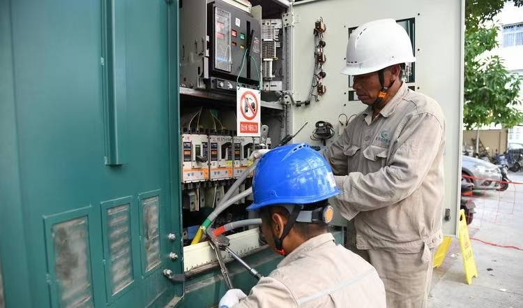
| Dispatch Emergency Crew | Verify site condition and public safety |
Isolation prevents secondary damage and ensures the area is safe before crews begin work.
3. Site Assessment and Root Cause Analysis
| Step | Objective |
|---|---|
| Visual inspection (tank, bushings) | Check for ruptures, leaks, or fire damage |
| Thermal and gas monitoring | Confirm fault origin using infrared and DGA equipment |
| Equipment testing (insulation, winding resistance) | Determine if transformer is salvageable |
| Forensic analysis (if needed) | For high-value or recurring failures |
Root cause findings help decide between repair, rebuild, or replacement.
4. Repair or Transformer Replacement Process
| For Distribution Transformers | For Power Transformers |
|---|---|
| Replace pole-mounted unit (1–3 hrs) | Crane-assisted removal and new install (12–48 hrs) |
| Install pad-mounted spare (4–6 hrs) | Site prep for mobile or spare unit (1–2 weeks) |
| Check connections and protection | Oil filtration, bushing check, OLTC calibration |
Larger units require transport, lifting, oil filling, and commissioning, often involving OEM service partners.
5. System Restoration and Testing
| Step | Purpose |
|---|---|
| Energize Step-by-Step | Prevent inrush current and voltage spikes |
| Confirm Load Balancing | Avoid secondary overload or feeder imbalance |
| SCADA System Updates | Confirm restoration and relay status |
| Notify Public or Critical Clients | Communicate outage resolution |
Utilities often coordinate with hospitals, emergency services, and industries to prioritize sensitive loads.
Real-World Case Study: Substation Transformer Blowout
- Location: 132/33 kV urban substation
- Incident: Flash, smoke, PRD activated, 25,000 customers lost power
- Response Time: Fault isolated in 0.7 sec by relay
- Crew Dispatch: Within 10 minutes
- Transformer Status: Internal arcing confirmed by DGA
- Replacement Time: 3 days (mobile substation used)
- Root Cause: Moisture ingress + insulation aging
- Outcome: Full restoration, preventive replacements scheduled across region
A fast response limited the outage window and prevented further equipment loss.
6. Post-Incident Reporting and Grid Reinforcement
| Task | Purpose |
|---|---|
| Event Logging and Reporting | Compliance with utility or regulatory body requirements |
| Equipment Audit in Area | Check condition of similar-aged transformers |
| Grid Resiliency Plan Update | Prevent repeat incident with better protection |
| Insurance or Warranty Claim | Recover repair/replacement cost if applicable |
Lessons learned help improve future response time and asset reliability.
How Can Blown Transformers Be Prevented Through Monitoring and Maintenance?
Transformer blowouts are rarely “sudden.” In most cases, the signs of failure—rising gas levels, overheating, insulation decay, or load stress—are present weeks or even months in advance. What separates a safe, long-living transformer from a catastrophic failure is often predictive monitoring and structured maintenance. By applying the right tools and protocols, utilities and industries can detect small issues early, avoid critical failures, and extend the lifespan of these multimillion-dollar assets.
Blown transformers can be effectively prevented through a combination of real-time condition monitoring—such as dissolved gas analysis (DGA), thermal imaging, moisture detection, and partial discharge sensors—and a well-executed maintenance program that includes regular oil filtration, bushing inspections, OLTC servicing, and electrical testing. These strategies identify early warning signs of internal faults, thermal stress, or insulation breakdown, allowing corrective action before damage becomes irreversible.
Transformers don’t have to fail unexpectedly—with proper attention, their lifespan can exceed 40 years.
Regular monitoring and preventive maintenance can prevent transformer blowouts.True
Most transformer failures are progressive and can be detected early through thermal, electrical, or chemical indicators.
Blown transformers are always unpredictable and cannot be prevented.False
Failures often show measurable signs in oil chemistry, temperature, and insulation resistance before catastrophic breakdown.
1. Critical Monitoring Techniques for Predictive Prevention
| Monitoring Method | Faults It Detects | Frequency |
|---|---|---|
| Dissolved Gas Analysis (DGA) | Arcing, overheating, insulation breakdown | Monthly to quarterly |
| Thermal Imaging (IR) | Hotspots in windings, bushings, or terminals | Quarterly or seasonal |
| Moisture Sensors | Insulation degradation risk due to water ingress | Continuous or monthly |
| Partial Discharge Monitoring | Dielectric failure, corona, or insulation cracks | Continuous for critical units |
| Load/Current Monitoring | Overloading, unbalanced phase conditions | Real-time (SCADA or IED) |
Real-time and scheduled monitoring provide early fault detection before visible or audible symptoms arise.
2. Routine Maintenance That Prevents Transformer Failure
| Maintenance Task | Purpose | Interval |
|---|---|---|
| Oil Sampling and Filtration | Removes moisture, acid, and sludge | 6–12 months |
| Bushing Inspection and Testing | Detects cracks, contamination, and dielectric failure | Annual |
| On-Load Tap Changer (OLTC) Servicing | Prevents contact wear and arc buildup | 3–5 years |
| Winding Resistance and Insulation Tests | Detects thermal or mechanical damage | Annually |
| Cooling System Check (Fans, Radiators) | Ensures proper temperature control | Monthly to quarterly |
Proactive maintenance helps preserve dielectric integrity and thermal performance under full-load conditions.
3. Digital Monitoring Tools for Continuous Oversight
| Technology | Functionality |
|---|---|
| SCADA Integration | Real-time parameter visualization and remote control |
| Online DGA Monitors | Tracks real-time gas generation trends |
| Thermal Cameras with AI | Detects abnormal temperature patterns automatically |
| Cloud-Based Asset Platforms | Predictive analytics for transformer fleets |
| Alarm Dashboards and Trending Tools | Prioritize critical units and detect deviations |
These systems enable condition-based maintenance (CBM) rather than time-based inspections.
4. Warning Signs Monitoring Can Detect Early
| Early Sign | Implication | Monitoring Method |
|---|---|---|
| Increase in acetylene (C₂H₂) | Internal arcing | DGA |
| Sudden hotspot on bushing | Impending dielectric failure | IR Imaging |
| Rise in moisture ppm | Breather failure or oil degradation | Moisture Sensor, Oil Test |
| Partial discharge spikes | Insulation cracks or corona in HV areas | PD Monitoring |
| Overcurrent pattern | Load mismanagement, secondary faults | SCADA Load Analytics |
Addressing these signs early prevents irreversible winding or insulation damage.
5. Maintenance Best Practices for High-Reliability Transformers
| Strategy | Benefit |
|---|---|
| Adopt Condition-Based Maintenance (CBM) | Aligns maintenance to actual asset health |
| Establish Transformer Health Index | Prioritizes which units need urgent attention |
| Cycle Oil Reconditioning/Regeneration | Restores dielectric strength and removes aging byproducts |
| Upgrade Aging Bushings and OLTCs | Prevents common failure points from reaching end-of-life |
| Maintain Fire Barriers and Spill Control | Mitigates damage if failure occurs despite prevention |
Prevention also includes protection system calibration (relays, PRDs, Buchholz) to minimize damage from unavoidable faults.
6. Real-World Prevention Case: 220 kV Transformer
- Location: Interregional substation
- Unit Age: 28 years
- Warning: Rising CO and C₂H₂ gas levels in DGA reports
- Action: Online DGA monitor triggered an alarm
- Response: Unit shut down, oil reconditioned, faulty OLTC contacts replaced
- Outcome: Fault isolated before arcing occurred
- Impact: Transformer life extended, no outage reported
This case highlights how gas trend analysis saved the transformer from catastrophic failure.
Summary Table: How Monitoring and Maintenance Prevent Blown Transformers
| Method | Prevents | Tool/Technique |
|---|---|---|
| Dissolved Gas Analysis | Arcing, overheating | Lab or online DGA system |
| Oil Filtration/Reclamation | Dielectric failure, sludge formation | Mobile oil processors |
| Thermal Imaging | Hotspot failure, poor connections | Infrared camera |
| Insulation Resistance Testing | Moisture-related breakdown | Megger, TTR, Tan Delta test |
| OLTC Maintenance | Arcing and voltage instability | Visual and contact wear checks |
| Moisture Monitoring | Insulation collapse | Karl Fischer, inline sensors |
| SCADA and Alarm Systems | Overload, imbalance, or cooling failure | Control room visualization |
Conclusion
When a transformer blows, it is typically the result of insulation breakdown, overloading, or external events like lightning or mechanical damage. The consequences can be severe—ranging from localized blackouts to fire hazards. Prompt diagnosis, emergency response, and preventive maintenance are key to minimizing downtime and ensuring public safety. As infrastructure modernizes, intelligent monitoring systems and robust design will reduce the frequency and severity of transformer failures.
FAQ
Q1: What does it mean when a transformer blows?
A1: When a transformer "blows," it usually means a catastrophic internal fault or electrical failure has occurred. This can result in a loud explosion, fire, or oil leakage, leading to immediate power outages and potential safety hazards.
Q2: What causes a transformer to blow?
A2: Common causes include:
Lightning strikes or surges
Short circuits or overloading
Insulation failure due to aging or moisture
Oil degradation or leakage in oil-immersed units
Poor maintenance or manufacturing defects
Q3: What are the signs of a blown transformer?
A3: Signs include:
A loud bang or explosion
Flames or smoke from the unit
Sudden power outage in the affected area
Burning smell or visible oil spill
Tripped breakers or alerts from monitoring systems
Q4: What happens to the electrical grid when a transformer blows?
A4: A blown transformer can cause:
Localized or widespread power outages
Voltage instability in the network
Load shifting to neighboring substations
Potential delays in emergency response and repairs depending on transformer size and role
Q5: How is a blown transformer repaired or replaced?
A5: Utility crews:
Isolate and de-energize the faulty transformer
Inspect and assess damage
If possible, repair minor faults on-site
For major damage, remove and replace the entire unit
Re-energize the line and monitor closely
Large transformers may take hours to days to replace depending on size, location, and availability.
References
"What Happens When a Transformer Blows?" – https://www.transformertech.com/transformer-blowout-explained
"Causes and Effects of Transformer Failures" – https://www.electrical4u.com/blown-transformer-causes
"Understanding Transformer Explosions and Safety Risks" – https://www.powermag.com/transformer-failure-explained
"Emergency Response to Substation Transformer Failure" – https://www.energycentral.com/c/ee/transformer-blowout-response
"Smart Grid News: Avoiding Catastrophic Transformer Failures" – https://www.smartgridnews.com/transformer-blowout-risks
"ScienceDirect: Diagnosing Transformer Explosions" – https://www.sciencedirect.com/blown-transformer-analysis
"ResearchGate: Case Studies on Transformer Failures" – https://www.researchgate.net/transformer-failure-case-study
"PowerGrid: What to Do When a Transformer Blows" – https://www.powergrid.com/blown-transformer-guide