A distribution transformer is a critical component in the electrical power system, serving as the final step in the electricity delivery chain. Positioned between the power grid and end users, these transformers reduce high transmission voltages to lower, usable levels suitable for homes, businesses, and small industries. Understanding how a distribution transformer works helps clarify how safe, stable, and efficient power reaches consumers.
What Is a Distribution Transformer?
Distribution transformers are the final voltage conversion devices in the electrical power distribution network. They reduce high transmission or sub-transmission voltages to levels suitable for residential, commercial, or small industrial use. Located close to the end-users, these compact and efficient transformers are built to deliver consistent, safe, and reliable power while operating continuously throughout the year.
A distribution transformer is an electrical device that steps down medium voltage (typically 11–33 kV) to a lower voltage (usually 400/230 V) for end-user consumption in residential, commercial, and light industrial areas. It is the last stage of voltage transformation in the power distribution system and is designed for continuous operation with high efficiency and low maintenance.
This article explains the function, features, classifications, and real-world applications of distribution transformers, equipping engineers, planners, and utilities with essential insights.
Distribution transformers convert medium-voltage electricity to usable low-voltage levels for homes and businesses.True
They are installed near load centers and operate continuously to provide final voltage transformation.
Distribution transformers are used to step up voltage for long-distance transmission.False
Step-up transformers are used at the generation side, while distribution transformers are step-down units installed near the load.
1. Core Function of a Distribution Transformer
Purpose:
- Final voltage step-down in power delivery
- Connects the secondary distribution system (11/33 kV) to end-user supply (400/230 V)
| Parameter | Typical Range |
|---|---|
| Primary voltage | 11 kV or 33 kV |
| Secondary voltage | 400 V (L-L) / 230 V (L-N) |
| Power rating | 16 kVA to 2500 kVA |
| Duty cycle | 24/7 continuous |
Key Characteristics:
- Operates at near-constant load
- High efficiency (95–99%)
- Air-cooled or oil-immersed
- Designed for minimal maintenance
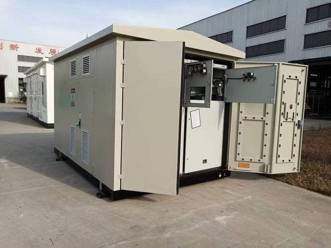
2. Construction and Configuration
Components:
- Core: Laminated silicon steel, minimizes eddy currents
- Windings: Copper or aluminum (primary and secondary)
- Tank: Oil-filled or dry-type enclosure
- Bushings: HV and LV terminals
- Tap changer: Manual or fixed, ±2.5–5% voltage adjustment
Configurations:
- Pole-mounted: 16–100 kVA (common in rural areas)
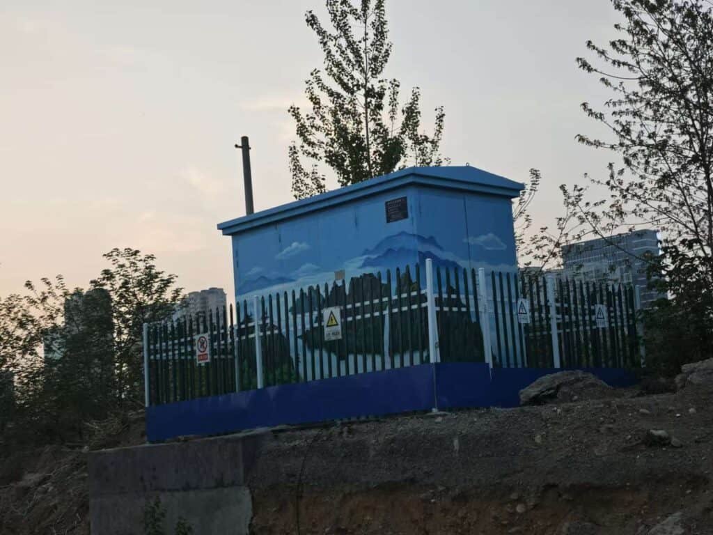
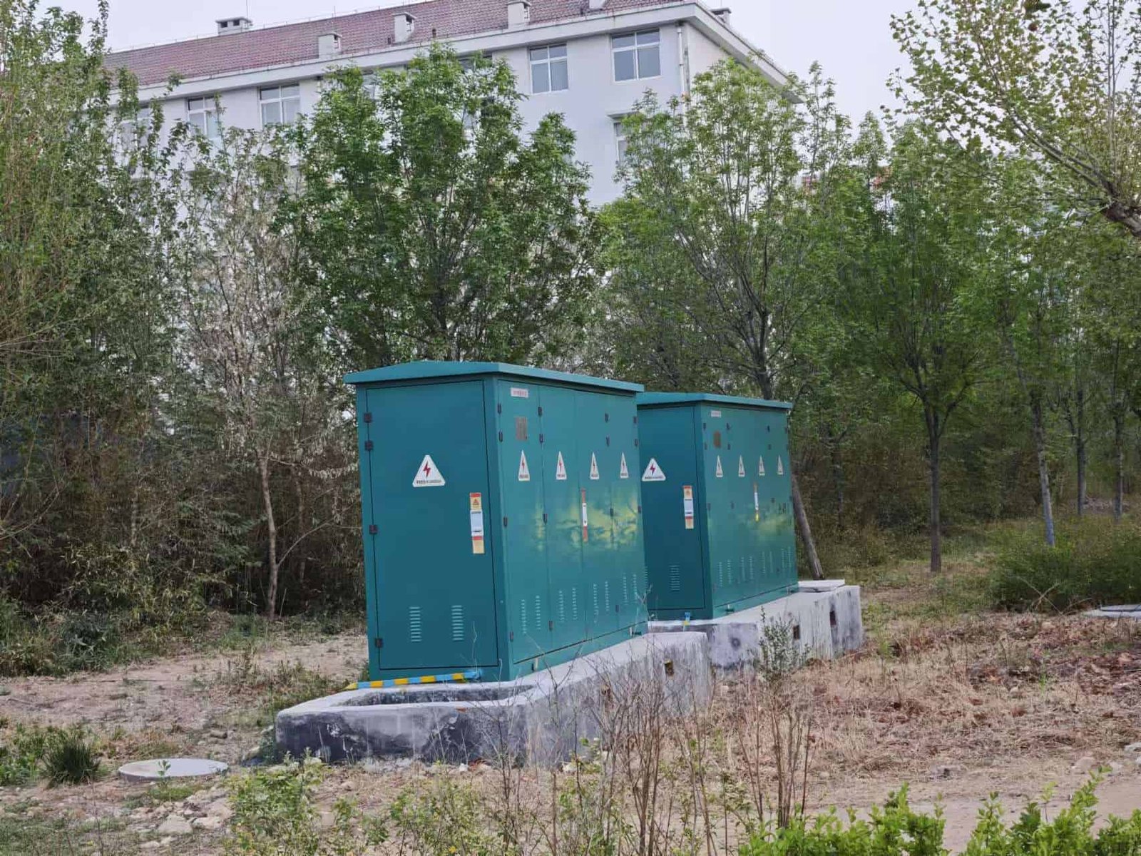
- Pad-mounted: 100–2500 kVA (urban or underground)
- Ground-mounted kiosk: Protected, weatherproof units
| Installation Type | Characteristics | Use Area |
|---|---|---|
| Pole-mounted | Compact, cost-effective | Rural, overhead lines |
| Pad-mounted | Enclosed, tamper-resistant | Urban, commercial |
| Kiosk type | Vented, lockable cabinet | Industrial parks |
3. Types of Distribution Transformers
| Type | Description | Application |
|---|---|---|
| Oil-Immersed | Windings immersed in insulating oil | Outdoor, high-capacity applications |
| Dry-Type | Air-cooled, epoxy resin insulation | Indoor, fire-sensitive zones |
| Single-Phase | One primary and one secondary winding | Remote/rural areas |
| Three-Phase | Three windings for 3-phase supply | Commercial/industrial locations |
| Pole-Mounted | Compact for mounting on power poles | Overhead distribution |
| Pad-Mounted | Ground-level enclosed design | Underground urban networks |
4. Technical Specifications
| Specification | Typical Values |
|---|---|
| Rated Power | 16 kVA – 2500 kVA |
| Voltage Ratio | 11/0.415 kV or 33/0.415 kV |
| Frequency | 50 Hz / 60 Hz |
| Efficiency | >98% at 50% load |
| Impedance | 4–6% (typical) |
| Insulation Class | A/B (oil) or F/H (dry) |
| Vector Group | Dyn11 (most common) |
5. Applications of Distribution Transformers
| Sector | Use Example |
|---|---|
| Residential | Supplies electricity to homes |
| Commercial | Powers shopping malls, offices |
| Rural Electrification | Delivers power over long feeders |
| Street Lighting | Step-down for public lighting grids |
| Institutional | Campuses, hospitals, schools |
| Construction Sites | Temporary distribution transformers |
6. Advantages of Distribution Transformers
| Advantage | Explanation |
|---|---|
| High efficiency | Maintains low losses during continuous duty |
| Compact and modular | Easy to install in various environments |
| Versatile installation | Can be pole-mounted, pad-mounted, or ground-fixed |
| Low maintenance requirement | Long life with periodic oil checks or thermal inspections |
| Affordable and standardized | Widely manufactured to international specs |
Summary Table: Distribution Transformer Overview
| Attribute | Value/Description |
|---|---|
| Function | Step down voltage for end-users |
| Voltage Levels | 11/0.415 kV, 33/0.415 kV |
| Typical Rating | 16–2500 kVA |
| Installation Types | Pole, pad, kiosk |
| Cooling Methods | Oil-immersed or dry-type |
| Application Areas | Residential, commercial, light industrial |
How Does a Distribution Transformer Function?
In modern power systems, delivering electricity at the right voltage level to the end-user is essential for safety, efficiency, and equipment compatibility. Distribution transformers fulfill this role as the final step in voltage transformation before electrical energy reaches homes, businesses, or light industrial loads. Operating continuously in diverse environments, they are engineered for long service life, low loss, and dependable output—but how exactly do they function?
A distribution transformer functions by using electromagnetic induction to step down medium voltage (typically 11 or 33 kV) from the distribution network to a lower, usable voltage (typically 400/230 V) for end-user consumption. It contains two sets of windings—primary and secondary—wrapped around a shared magnetic core. When alternating current flows through the primary winding, it creates a magnetic field that induces a proportional voltage in the secondary winding, enabling safe and efficient voltage conversion.
This article offers a technically detailed explanation of how distribution transformers work, including core theory, flux flow, voltage transformation principles, and system integration.
Distribution transformers operate through electromagnetic induction to convert medium voltage to low voltage for residential and commercial use.True
They rely on magnetic flux coupling between primary and secondary windings to enable voltage conversion without direct electrical connection.
Distribution transformers contain rotating parts to convert mechanical energy into electrical energy.False
Unlike generators, transformers have no moving parts and function solely through magnetic induction.
1. Basic Working Principle: Electromagnetic Induction
The Foundation:
A distribution transformer is a static device that relies on Faraday’s Law of Electromagnetic Induction:
- An alternating current (AC) in the primary winding creates a changing magnetic field
- This magnetic flux flows through the transformer core
- A proportional voltage is induced in the secondary winding via magnetic coupling
| Core Component | Function |
|---|---|
| Primary winding | Receives input voltage from 11 or 33 kV line |
| Magnetic core | Guides the alternating magnetic flux |
| Secondary winding | Outputs the stepped-down voltage (400/230 V) |
2. Voltage Transformation Ratio
The amount of voltage step-down is determined by the turns ratio between the primary and secondary windings:
$$\frac{V_1}{V_2} = \frac{N_1}{N_2}$$
Where:
- $V_1$: Primary (input) voltage
- $V_2$: Secondary (output) voltage
- $N_1$: Number of primary turns
- $N_2$: Number of secondary turns
Example:
For a 11/0.415 kV transformer:
- $N_1 > N_2$
- Step-down ratio ≈ 26.5:1
- Each secondary winding supplies 230 V (line to neutral)
- 400 V between phases (line-to-line) in a three-phase setup
3. Core and Flux Behavior
The magnetic core:
- Is made of laminated silicon steel sheets
- Minimizes eddy current losses
- Maximizes flux linkage between windings
In operation:
- The alternating current in the primary creates a sinusoidal magnetic flux (Φ)
- The same flux passes through the secondary winding
- Induces AC voltage in the secondary side at a lower magnitude
Core design and material significantly affect transformer efficiency and noise levels.
4. Cooling and Insulation
Cooling Types:
- Oil-Immersed (ONAN): Most common, uses mineral or ester oil for cooling and insulation
- Dry-Type (AN): Uses air to cool epoxy-encapsulated windings, ideal for indoor/fire-sensitive areas
| Cooling Method | Feature | Use Case |
|---|---|---|
| ONAN | Natural oil + air convection | Outdoor, higher capacities |
| ONAF | Oil Natural + Air Forced (fans) | Dense urban substations |
| Dry-Type | No oil, resin insulation | Hospitals, malls, basements |
Insulation:
- Oil acts as both dielectric and heat absorber
- Windings insulated with paper, enamel, or resin
- Bushings isolate HV and LV terminals
5. Tap Changer for Voltage Regulation
Some transformers include off-circuit tap changers to adjust output voltage:
| Feature | Details |
|---|---|
| Tap range | ±2.5% or ±5% in 2.5% steps |
| Operation | Manual (off-load) |
| Use | Compensate for grid voltage variation |
Larger distribution transformers may include on-load tap changers (OLTC) for automatic voltage control, but this is rare in smaller units.
6. Internal Protection Mechanisms
To protect against electrical and thermal faults:
| Protection Feature | Purpose |
|---|---|
| Pressure relief valve | Releases excess gas in case of internal arc |
| Buchholz relay (in larger units) | Detects gas from insulation breakdown |
| Surge arresters | Deflect overvoltage (lightning, switching) |
| Fuses or breakers | Isolate faulted transformer sections |
These features help prevent transformer damage and fire hazards.
7. Real-Life Example: Residential Use Case
Pole-Mounted Transformer:
- Rating: 100 kVA, 11/0.415 kV, Dyn11
- Input: 3-phase 11 kV from distribution feeder
- Output: 400 V (L-L), 230 V (L-N) to residential homes
- Powers \~20–30 households depending on load
Functional Flow:
- Receives 11 kV →
- Converts to magnetic flux in core →
- Flux induces 400/230 V in secondary →
- Supplies LV panel and meter boxes of homes
Summary Table: How a Distribution Transformer Functions
| Step | Action |
|---|---|
| Primary voltage input | 11/33 kV enters primary winding |
| Magnetic flux generation | Alternating current induces flux in core |
| Voltage induction | Flux induces lower voltage in secondary |
| Voltage output | 400/230 V delivered to consumers |
| Continuous operation | Maintains 24/7 voltage conversion |
| Cooling and protection | Oil, air, and built-in safety devices |
What Are the Main Types of Distribution Transformers?

Distribution transformers are the final voltage step-down devices in the power distribution network, ensuring safe, usable voltage levels for end-users. However, not all distribution transformers are alike. They vary based on insulation method, phase configuration, installation type, and enclosure design—each tailored to meet specific environmental, operational, and load conditions. Selecting the correct transformer type is crucial for system reliability, cost efficiency, and regulatory compliance.
The main types of distribution transformers include oil-immersed and dry-type (based on insulation and cooling), single-phase and three-phase (based on load connection), and pole-mounted, pad-mounted, and ground-mounted types (based on installation). Each type is designed to meet specific application demands in residential, commercial, and industrial settings.
This article offers a comprehensive guide to the major distribution transformer types, explaining their construction, functionality, use cases, and selection criteria.
Distribution transformers come in various types such as oil-filled, dry-type, pole-mounted, pad-mounted, and can be configured for single or three-phase systems.True
These transformer types differ in cooling method, phase configuration, and physical installation design to suit diverse distribution network needs.
Only one type of distribution transformer is used across all power distribution networks globally.False
Distribution transformers are chosen based on voltage class, environment, load type, and installation site, resulting in multiple transformer types.
1. Oil-Immersed Distribution Transformers
Description:
- Windings and core are submerged in insulating oil (mineral, silicone, or ester)
- Oil serves both cooling and insulating functions
| Feature | Details |
|---|---|
| Cooling type | ONAN (Oil Natural Air Natural) |
| Enclosure | Sealed tank with conservator (optional) |
| Voltage classes | 11 kV, 22 kV, 33 kV primaries |
| Power range | 25 kVA – 2500 kVA |
Use Case:
- Rural distribution poles
- Outdoor substations
- Industrial loads
Pros:
- Cost-effective
- Proven design
- High overload tolerance
Cons:
- Fire risk (mineral oil)
- Requires periodic oil testing and maintenance
2. Dry-Type Distribution Transformers
Description:
- Windings are encapsulated in epoxy resin or varnished and cooled by air
- No oil or liquid involved
| Feature | Details |
|---|---|
| Cooling type | AN (Air Natural) or AF (Air Forced) |
| Safety class | Fire-retardant (Class F/H insulation) |
| Power range | 25 kVA – 2500 kVA |
| Environment | Indoor, ventilated rooms, fire zones |
Use Case:
- Commercial buildings
- Hospitals, airports
- Underground substations
- Environmentally sensitive sites
Pros:
- Fire safe
- Minimal maintenance
- No oil leaks
Cons:
- More expensive upfront
- Lower overload capacity
- Sensitive to humidity and dust
3. Single-Phase Distribution Transformers
Description:
- Designed for one-phase supply
- Common in areas with light, unbalanced loads
| Feature | Details |
|---|---|
| Supply type | 1Φ in / 1Φ out or 1Φ in / 3Φ out |
| Typical rating | 5 kVA – 100 kVA |
| Installation | Mostly pole-mounted |
Use Case:
- Rural homes and farms
- Street lighting circuits
- Temporary site power
Pros:
- Low cost
- Easy to install
- Ideal for scattered loads
Cons:
- Not suitable for balanced 3-phase loads
- Limited power capacity
4. Three-Phase Distribution Transformers
Description:
- Handles three-phase loads, supplying 400 V (line-to-line) and 230 V (line-to-neutral)
| Feature | Details |
|---|---|
| Supply type | 3Φ in / 3Φ out |
| Voltage ratio | Common: 11/0.415 kV or 33/0.415 kV |
| Power rating | 100 kVA – 2500 kVA |
Use Case:
- Industrial and commercial zones
- Multi-story buildings
- Urban substations
Pros:
- Higher efficiency
- Balanced power delivery
- Compact for rated capacity
Cons:
- Slightly complex installation
- Requires more robust protection systems
5. Pole-Mounted Transformers
Description:
- Compact oil-immersed units installed on utility poles
- Typically single-phase or small three-phase
| Feature | Specification |
|---|---|
| Voltage level | 11/0.415 kV or 33/0.415 kV |
| Power range | 10 – 250 kVA |
Use Case:
- Rural electrification
- Light commercial zones
- Areas with overhead power lines
Pros:
- Space-saving
- Easy grid integration
- Low civil infrastructure cost
Cons:
- Susceptible to weather
- Harder to access for maintenance
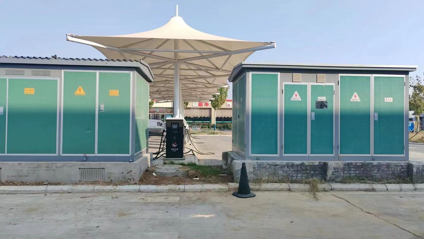
6. Pad-Mounted Transformers
Description:
- Tamper-resistant units placed at ground level
- Fully enclosed and safe for public access
| Feature | Specification |
|---|---|
| Cooling | Oil-filled or dry-type |
| Voltage level | 11/0.415 kV or 33/0.415 kV |
| Power range | 100 – 2500 kVA |
Use Case:
- Urban neighborhoods
- Industrial parks
- Underground cable networks
Pros:
- Tamper-proof
- Safe near pedestrian areas
- Aesthetic compatibility
Cons:
- Requires civil platform
- May be costlier than pole-mounting
Summary Table: Main Types of Distribution Transformers
| Type | Phase | Cooling | Typical Use Case |
|---|---|---|---|
| Oil-Immersed | 1Φ / 3Φ | Oil | Outdoor substations, rural grids |
| Dry-Type | 1Φ / 3Φ | Air | Indoor, fire-sensitive buildings |
| Single-Phase | 1Φ | Oil/Dry | Farms, poles, scattered loads |
| Three-Phase | 3Φ | Oil/Dry | Commercial, industrial, substations |
| Pole-Mounted | 1Φ / 3Φ | Oil | Overhead rural/urban feeders |
| Pad-Mounted | 3Φ | Oil/Dry | Underground networks, cities |
What Are the Typical Ratings and Standards?
Distribution transformers must meet rigorous technical ratings and international standards to ensure they operate safely, efficiently, and reliably across diverse power systems. These specifications govern the transformer's power capacity, voltage levels, insulation class, impedance, efficiency, cooling methods, and more. Adhering to globally accepted standards like IEC, ANSI/IEEE, IS, and NEMA is critical for compatibility, regulatory compliance, and long-term performance.
Typical ratings for distribution transformers include power capacities from 16 kVA to 2500 kVA, primary voltages of 11 kV or 33 kV, and secondary voltages of 400/230 V. Key standards such as IEC 60076, ANSI C57, IS 1180, and NEMA TP-1 define construction, testing, efficiency, insulation, and environmental requirements for transformer design and operation.
This article explains the most important rating parameters and standard guidelines that define and govern distribution transformer performance worldwide.
Distribution transformers must comply with internationally recognized standards such as IEC, ANSI, IS, and NEMA for design, performance, and safety.True
These standards ensure compatibility, reliability, and efficiency across global electrical infrastructure.
Distribution transformer ratings are universal and do not vary by region or application.False
Ratings such as voltage class, frequency, insulation, and cooling method vary based on country-specific grid codes, environmental conditions, and application needs.
1. Typical Power Ratings (kVA)
Distribution transformers are rated in kilovolt-amperes (kVA), indicating the apparent power they can handle.
| Common kVA Ratings | Application Scope |
|---|---|
| 16, 25, 63, 100 kVA | Rural, light commercial, small buildings |
| 160, 250, 315, 500 kVA | Urban residential blocks, small industry |
| 630, 800, 1000, 1250 kVA | Multi-storey complexes, malls |
| 1600, 2000, 2500 kVA | Industrial facilities, utility substations |
Transformer ratings are selected based on peak load, diversity factor, and future expansion margin.
2. Typical Voltage Ratings
A. Primary (Input) Voltage
- Standard: 11 kV, 22 kV, or 33 kV
- Depends on sub-transmission system voltage
B. Secondary (Output) Voltage
- Typically: 400 V line-to-line, 230 V line-to-neutral
- Supports 3-phase and 1-phase consumer loads
| Voltage Ratio Examples | Use Case |
|---|---|
| 11/0.415 kV | Most common distribution setup |
| 33/0.415 kV | Long rural feeders, high voltage input |
| 22/0.433 kV (less common) | Regional standards (e.g., Australia, parts of Asia) |
Transformers may include ±2.5% or ±5% off-load tap changers for voltage regulation.
3. Standards Governing Distribution Transformers
| Standard | Region/Body | Description |
|---|---|---|
| IEC 60076 | International (IEC) | Specifies ratings, testing, construction |
| IS 1180 / IS 2026 | India (BIS) | Indigenous transformer design/testing norms |
| ANSI C57.12.x | USA (IEEE/ANSI) | North American standards for design, safety |
| NEMA TP-1 | USA (NEMA) | Energy efficiency performance requirements |
| CSA C2.1 | Canada | General requirements for power transformers |
| EN 50588-1 | Europe (CENELEC) | Eco-design and loss limitations (ErP) |
4. Insulation Classes and Temperature Ratings
Transformer insulation is classified based on maximum temperature limits:
| Insulation Class | Max Hot Spot Temperature (°C) | Common Use |
|---|---|---|
| Class A | 105°C | Oil-immersed |
| Class B | 130°C | Older dry-type |
| Class F | 155°C | Dry-type transformers |
| Class H | 180°C | High-temperature, resin-encapsulated |
Temperature rise limits as per IEC 60076-2:
- Oil-filled: 55°C or 65°C above ambient
- Dry-type: 80°C to 115°C rise, depending on class
5. Impedance and Short-Circuit Capability
| Rating Parameter | Typical Value | Purpose |
|---|---|---|
| Impedance (%) | 4% to 6% (standard) | Limits fault current, defines voltage drop |
| Short-circuit withstand | 2 seconds (IEC 60076-5) | Defines thermal/mechanical endurance |
Higher impedance = reduced fault current, but increased voltage drop.
6. Efficiency and Loss Standards
Defined by:
- No-load loss (core loss)
- Load loss (copper loss)
| Standard | Efficiency Criteria |
|---|---|
| IEC 60076-20 | Defines eco-design Tier I & II losses |
| IS 1180 Part 1 | India’s energy-efficient transformer classes |
| NEMA TP-1 | Minimum energy performance in North America |
| Star Label / Level | Max Losses @ 50% Load (for 100 kVA, 11/0.415 kV) |
|---|---|
| Star 1 (Basic) | \~1240 W (load) / \~220 W (no-load) |
| Star 5 (Highest) | \~960 W (load) / \~140 W (no-load) |
7. Cooling Classifications
| Code | Description |
|---|---|
| ONAN | Oil Natural Air Natural |
| ONAF | Oil Natural Air Forced (with fans) |
| AN | Air Natural (dry-type) |
| AF | Air Forced (forced cooling dry-type) |
IEC 60076-2 defines cooling and temperature rise testing.
8. Vector Group Classifications
Describes the winding configuration and phase displacement.
| Common Vector Groups | Description | Application |
|---|---|---|
| Dyn11 | Delta primary, star secondary, 30° lag | Standard in LV distribution |
| Yyn0 | Star-star, no phase shift | Balanced, low load centers |
| Yd1 | Star primary, delta secondary | Generation step-up |
Must match vector group when operating transformers in parallel.
Summary Table: Typical Ratings and Standards for Distribution Transformers
| Parameter | Typical Values / Range |
|---|---|
| Power Rating | 16–2500 kVA |
| Primary Voltage | 11, 22, or 33 kV |
| Secondary Voltage | 0.415 kV (L-L), 230 V (L-N) |
| Efficiency | ≥98% at 50% load (Star-rated) |
| Cooling Type | ONAN, ONAF, AN, AF |
| Insulation Class | A, B, F, H |
| Governing Standards | IEC 60076, IS 1180, ANSI C57, NEMA TP-1 |
| Vector Group | Dyn11 (most common) |
What Are the Key Design Features and Components?
Distribution transformers are engineered for high-efficiency voltage reduction, operating continuously with minimal maintenance. Their performance and reliability depend on precise electrical, magnetic, thermal, and mechanical design features, as well as the quality of internal and external components. Understanding these components is crucial for selecting, maintaining, or troubleshooting transformers in any power distribution system.
The key design features and components of a distribution transformer include the magnetic core, primary and secondary windings, insulating and cooling systems (such as transformer oil or air), the tank and enclosure, bushings, tap changer, and various protection devices. These elements are carefully configured to ensure efficient voltage transformation, heat dissipation, dielectric safety, and long service life.
This article provides a complete overview of the physical structure, internal parts, and engineering design considerations that make distribution transformers dependable across diverse applications.
A distribution transformer consists of multiple integrated components, including a magnetic core, copper windings, insulation, bushings, a tank, and protective devices.True
Each component plays a crucial role in enabling safe, efficient, and continuous voltage transformation in electrical networks.
The internal design of a distribution transformer is identical for all voltage ratings and cooling methods.False
Transformer design varies significantly depending on application, voltage class, cooling technique, and environmental requirements.
1. Magnetic Core
Function:
- Provides the path for magnetic flux between windings
- Facilitates electromagnetic induction for voltage transformation
| Feature | Details |
|---|---|
| Material | Cold-rolled grain-oriented (CRGO) silicon steel |
| Core shape | Core-type (most common), shell-type |
| Loss minimization | Laminated design reduces eddy currents |
Design Consideration:
- Low core loss (watts/kg) for high efficiency
- High permeability and mechanical rigidity
- Minimizes humming (magnetostriction)
2. Primary and Secondary Windings
Function:
- Carry current and induce voltage between input and output
- Insulated from each other and from the core
| Parameter | Detail |
|---|---|
| Material | Copper (preferred), Aluminum (cost-efficient) |
| Insulation | Paper, enamel, or resin (dry-type) |
| Arrangement | Cylindrical, layer, or disc windings |
Design Consideration:
- Thermal rating for load handling
- Impulse strength against lightning or switching surges
- Spacing and support to prevent short-circuit deformation
3. Insulating System
Function:
- Electrically isolates windings and supports dielectric strength
- Also provides thermal insulation and mechanical stability
| Type | Description |
|---|---|
| Oil-based | Mineral or synthetic ester oils |
| Solid insulation | Kraft paper, Nomex, epoxy resin |
| Dry-type resin | Epoxy or cast resin encapsulation |
Proper insulation is critical for withstand voltage, temperature class, and moisture resistance.
4. Cooling System
Purpose:
- Removes heat generated by losses in windings and core
| Cooling Type | Description | Common Use |
|---|---|---|
| ONAN | Oil Natural Air Natural | Standard oil-filled transformers |
| ONAF | Oil Natural Air Forced (fans) | High-load transformers |
| AN | Air Natural (dry-type) | Indoor, fire-sensitive areas |
| AF | Air Forced | Compact units with limited airflow |
Key Components:
- Radiators or fins
- Cooling ducts
- Air vents or fan assemblies
5. Transformer Tank and Enclosure
Function:
- Houses and protects the internal components
- Provides mechanical protection, oil containment, and grounding interface
| Type | Description |
|---|---|
| Sealed tank | Pressurized, maintenance-free |
| Free-breathing | Conservator tank with breather |
| Dry-type enclosure | Vented steel/aluminum housing |
Optional Features:
- Conservator tank
- Silica gel breather
- Pressure relief valve
- Drain and sampling valves
6. Bushings
Function:
- Provide safe connection between external circuits and internal windings
- Insulate conductors where they pass through the tank
| Bushing Type | Voltage Level Supported |
|---|---|
| Porcelain (oil-filled) | Up to 33 kV |
| Epoxy resin (dry-type) | Low- to medium-voltage applications |
Bushings are critical failure points—must be monitored for cracks, tracking, or oil leaks.
7. Tap Changer (Off-Circuit or On-Load)
Function:
- Adjusts the winding turns ratio to regulate secondary voltage
- Usually ±2.5% to ±5% in multiple steps
| Type | Description |
|---|---|
| Off-circuit tap changer (OCTC) | Manual, requires shutdown |
| On-load tap changer (OLTC) | Motorized, adjusts under load |
Most distribution transformers use manual OCTCs for cost and simplicity.
8. Protection Devices and Accessories
| Component | Purpose |
|---|---|
| Pressure relief valve | Releases gas during internal faults |
| Buchholz relay | Detects gas accumulation from arcing |
| Surge arresters | Protect from lightning and overvoltage |
| Temperature sensors | Monitor oil or winding temperatures |
| Oil level indicator | Shows minimum and maximum fill levels |
| Silica gel breather | Maintains dry air above oil |
Protection systems help extend lifespan and reduce failure risk.
9. Earthing and Grounding System
- Earthing terminal on tank
- Ensures safe discharge of fault current
- Prevents hazardous voltages during insulation failure
| Safety Feature | Description |
|---|---|
| Neutral earthing | For grounded secondary configurations |
| Body/tank grounding | For lightning/fault protection |
Summary Table: Key Components of a Distribution Transformer
| Component | Primary Function |
|---|---|
| Magnetic Core | Conducts magnetic flux |
| Windings (Primary/Secondary) | Transfers electrical energy |
| Insulation | Dielectric separation, thermal support |
| Cooling System | Heat dissipation via oil or air |
| Tank/Enclosure | Mechanical protection and containment |
| Bushings | High-voltage terminals with insulation |
| Tap Changer | Voltage adjustment |
| Protection Devices | Safety during faults or abnormal operation |
| Grounding Terminals | Earth fault path and safety compliance |
Where Are Distribution Transformers Used and Why Are They Important?
Distribution transformers play a vital role at the final stage of the power delivery system, ensuring that high-voltage electricity from transmission lines is safely and efficiently converted to low-voltage power for consumers. Found on utility poles, in ground-mounted cabinets, or inside buildings, these transformers are critical for the safe and seamless functioning of electrical infrastructure across cities, towns, and rural areas.
Distribution transformers are used in residential neighborhoods, commercial buildings, rural areas, light industrial sites, public institutions, and infrastructure networks. They are important because they reduce high transmission voltages (11–33 kV) to safe, usable voltages (400/230 V), enabling efficient and continuous delivery of electricity to homes, businesses, and essential services.
This article explores the specific locations where distribution transformers are deployed and explains why their role is indispensable in modern electrical systems.
Distribution transformers are installed close to end-users to convert medium-voltage power into safe low-voltage electricity for daily use.True
These transformers are the final voltage step-down devices in the grid and are necessary for reliable household and commercial electricity supply.
The power grid can function without distribution transformers by supplying transmission voltage directly to homes.False
Transmission voltage is far too high for safe residential or commercial use; distribution transformers are essential to reduce it to acceptable levels.
1. Residential Areas (Urban and Suburban)
Use:
- Supply electricity to houses, apartment blocks, gated communities
Function:
- Step down from 11 kV or 33 kV to 400 V three-phase or 230 V single-phase
Why Important:
- Ensure safe voltage for domestic appliances
- Balance loads across phases
- Enable household-level metering
| Location Type | Common Transformer Rating |
|---|---|
| Urban neighborhoods | 250–630 kVA, 11/0.415 kV |
| Apartment buildings | 500–1250 kVA, pad-mounted |
| Suburban homes | 100–250 kVA, pole-mounted |
2. Commercial Complexes and Institutions
Use:
- Office buildings, hospitals, schools, shopping malls, airports
Function:
- Deliver stable and uninterrupted three-phase power
- Support HVAC systems, elevators, lighting, and IT infrastructure
Why Important:
- Power-sensitive environments require low voltage fluctuations
- Often deployed as dry-type units for fire safety and indoor compatibility
| Institution Type | Typical Installation |
|---|---|
| Hospital | 1000–1600 kVA, dry-type |
| Shopping mall | 1250–2000 kVA, pad-mounted |
| University campus | 250–800 kVA, ground-mounted |
3. Rural Electrification
Use:
- Villages, farms, remote homes, small community centers
Function:
- Bring electricity from long 33/11 kV feeders to scattered end users
Why Important:
- Enables economic development and improved quality of life
- Powers irrigation pumps, lighting, and communication systems
| Scenario | Typical Rating & Type |
|---|---|
| Rural homes | 25–63 kVA, single-phase, pole-mounted |
| Agriculture fields | 63–160 kVA, three-phase, oil-immersed |
4. Light Industrial and Manufacturing Areas
Use:
- Small-scale factories, workshops, cold storage units, production facilities
Function:
- Provide stable three-phase power for motors, compressors, furnaces, etc.
Why Important:
- Ensure equipment safety, voltage regulation, and fault protection
- Serve as backbone for regional industrial growth
| Industry Type | Common Transformer Specs |
|---|---|
| Cold storage | 315–630 kVA, oil-immersed |
| Textile mill | 800–1250 kVA, dry-type or sealed |
| Food processing unit | 500–1000 kVA, pad-mounted |
5. Public Infrastructure and Utilities
Use:
- Railway stations, metro systems, traffic lighting, water treatment plants
Function:
- Deliver clean, reliable power for critical infrastructure operations
Why Important:
- Ensure 24/7 service continuity
- Power systems must meet safety, voltage tolerance, and environmental standards
| Facility Type | Transformer Use Case |
|---|---|
| Railway station | 1250–2000 kVA, indoor dry-type |
| Traffic management grid | 250 kVA, pole-mounted |
| Pumping station | 630–1000 kVA, outdoor oil-type |
6. Underground and Urban Distribution Networks
Use:
- Cities with dense populations or aesthetic concerns
Function:
- Pad-mounted or kiosk transformers integrate with underground cable systems
Why Important:
- Prevent exposure to environmental hazards
- Reduce noise and visual impact
| Area Type | Recommended Transformer Type |
|---|---|
| Downtown zones | 630–1600 kVA pad-mounted |
| Heritage districts | Enclosed dry-type |
| Business districts | Ground-kiosk installations |
7. Temporary Power Supply and Construction Sites
Use:
- Construction projects, roadworks, event venues
Function:
- Provide temporary access to regulated power supply
Why Important:
- Enables equipment operation and safety systems during construction
| Use Case | Common Ratings & Type |
|---|---|
| Infrastructure project | 250–500 kVA, mobile units |
| Outdoor event | 100–250 kVA, trailer-mounted |
Summary Table: Distribution Transformer Use Cases
| Application Area | Power Rating Range | Installation Type | Key Importance |
|---|---|---|---|
| Residential | 25–630 kVA | Pole/pad-mounted | Household supply, load balancing |
| Commercial | 500–2000 kVA | Dry-type, pad-mounted | HVAC, elevators, IT loads |
| Rural | 16–160 kVA | Pole-mounted, single-Φ | Agricultural and village electrification |
| Light Industry | 315–1600 kVA | Pad-mounted, oil type | Motor operation, production facilities |
| Infrastructure | 250–2000 kVA | Dry-type, sealed units | Public services, continuous supply |
| Urban Underground | 630–1600 kVA | Pad/kiosk-mounted | Hidden, compact, noise-free installations |
| Temporary Power | 100–500 kVA | Mobile trailer units | Site power and temporary events |
Why Distribution Transformers Are Important
- 🔌 Voltage Regulation: Step down high voltage to levels safe for consumer use
- 🛡️ System Protection: Isolate faults and stabilize grid voltage
- 💡 24/7 Operation: Operate reliably with minimal supervision
- 🌍 Accessibility: Bring power to remote and underserved locations
- 🏗️ Infrastructure Backbone: Power essential services, industries, and homes
- 💰 Cost Efficiency: Optimize grid investment by reducing energy losses near the point of use
Conclusion
Distribution transformers play a foundational role in ensuring that electrical energy is safely and efficiently delivered to end users. By stepping down high voltages to practical levels and maintaining reliable operation in diverse environments, these transformers enable the modern world to function—from residential lighting to industrial machinery. Understanding their operation and characteristics is essential for power engineers, utilities, and infrastructure planners alike.
FAQ
Q1: What is a distribution transformer?
A1: A distribution transformer is a type of step-down transformer used in the final stage of the electrical power distribution system. It reduces the high voltage from transmission lines to a lower, usable voltage level suitable for residential, commercial, or light industrial use.
Q2: How does a distribution transformer work?
A2: It operates on the principle of electromagnetic induction. High-voltage electricity enters the transformer's primary winding, creating a magnetic field in the core. This magnetic field induces a lower voltage in the secondary winding, which is then supplied to consumers at safe voltage levels (e.g., 400V or 230V).
Q3: Where are distribution transformers typically located?
A3: Distribution transformers are commonly mounted on:
Utility poles (pole-mounted transformers)
Concrete pads (pad-mounted transformers)
Underground vaults in urban areas
They are strategically placed near end users to minimize voltage drop and power loss.
Q4: What are the key features of a distribution transformer?
A4: Key features include:
Step-down voltage capability
Compact design for easy installation
Efficient performance at low loads
Oil-immersed or dry-type insulation
Single-phase or three-phase configurations
Q5: What role does a distribution transformer play in the power grid?
A5: Distribution transformers are the critical link between the high-voltage transmission system and end users. They ensure electricity is delivered at safe, usable voltages, helping maintain power quality, system reliability, and energy efficiency at the consumer level.
References
"What is a Distribution Transformer?" – https://www.transformertech.com/distribution-transformer-basics – Transformer Tech
"Working Principle and Applications of Distribution Transformers" – https://www.powermag.com/distribution-transformer-working – Power Magazine
"Types and Functions of Distribution Transformers" – https://www.electrical4u.com/distribution-transformer – Electrical4U
"Role of Distribution Transformers in Power Networks" – https://www.researchgate.net/distribution-transformer-grid-role – ResearchGate
"Distribution Transformers: Design and Operation" – https://www.sciencedirect.com/distribution-transformer-operation – ScienceDirect
"Energy Central: Understanding Distribution Transformer Efficiency" – https://www.energycentral.com/c/ee/distribution-transformer-performance – Energy Central
"Smart Grid Applications of Distribution Transformers" – https://www.smartgridnews.com/distribution-transformer-applications – Smart Grid News
"PowerGrid Overview: How Distribution Transformers Serve Communities" – https://www.powergrid.com/distribution-transformer-role – PowerGrid