Shell-type transformers are one of the two main classifications of transformer core construction, the other being core-type. The unique structural design of shell-type transformers provides distinct electrical, mechanical, and magnetic characteristics that suit them for specific industrial and high-power applications. Understanding their construction and advantages is key to selecting the right transformer for a given application.
What Is Core Construction and Magnetic Path in Transformers?
The transformer core is the central component through which magnetic flux flows, enabling voltage transformation via electromagnetic induction. Its construction directly affects the efficiency, noise level, size, and loss characteristics of the transformer. If the magnetic path is poorly designed—featuring high reluctance, leakage, or saturation—the transformer will waste energy, generate heat, and underperform. Therefore, precise engineering of the magnetic path and core material selection is critical for performance, longevity, and regulatory compliance.
The core construction and magnetic path in a transformer define how magnetic flux flows through the laminated iron core between the primary and secondary windings. Typically made of Cold Rolled Grain Oriented (CRGO) steel, the core is stacked or wound to minimize core losses and optimize magnetic coupling. The magnetic path forms a continuous loop across the limbs and yokes, ensuring efficient flux linkage and minimal leakage, which is essential for voltage regulation and low-loss performance.
The magnetic core of a transformer carries current.False
The core carries magnetic flux, not electric current. Electric current flows in the windings surrounding the core.
CRGO steel is used in transformer cores because of its magnetic properties.True
CRGO (Cold Rolled Grain Oriented) steel has high permeability and low hysteresis loss, making it ideal for magnetic flux conduction.
🧲 Core Geometry and Magnetic Circuit Design
| Core Type | Description | Application |
|---|---|---|
| Core Type (Laminated) | Magnetic limbs with windings placed concentrically around them | Most power and distribution transformers |
| Shell Type | Winding enclosed by magnetic shell with dual flux paths | Specialty transformers (e.g., furnace duty) |
| Toroidal Core | Ring-shaped core with uniform winding | Compact designs, electronic transformers |
| Three-Leg Core | Standard three-phase transformer with yokes and three limbs | Balanced three-phase operation |
| Five-Leg Core | Additional side limbs to reduce zero-sequence flux | Transformers connected to ungrounded systems |
Magnetic flux loops through the yoke and limbs, forming a closed magnetic circuit. Each leg serves a phase in a three-phase transformer, while the yokes connect the magnetic path vertically.
🏗️ Core Materials and Lamination Structure
| Material | Properties | Typical Thickness | Benefit |
|---|---|---|---|
| CRGO Silicon Steel | High permeability, low core loss | 0.23 mm – 0.30 mm | Industry standard for power transformers |
| Amorphous Metal | Ultra-low core losses, brittle structure | 0.025 mm | Used in high-efficiency distribution units |
| Non-Grain Oriented Steel | Uniform properties in all directions | 0.5 mm | Used in rotating machines, not ideal for transformers |
| Nanocrystalline Alloys | Emerging tech with superior properties | ≤0.02 mm | Future potential for compact cores |
CRGO steel is grain-oriented to align the magnetic domain with the flux path, drastically reducing hysteresis and eddy current losses.
🔍 Magnetic Path Visualization
| Segment | Magnetic Role | Path Direction |
|---|---|---|
| Core Limb | Vertical conductor of magnetic flux | Top to bottom (or reverse) |
| Yoke | Connects limbs, completing the loop | Horizontal flux transfer |
| Joints | Mitred or butt lap connections between laminations | Potential flux leakage points |
| Air Gaps | Avoided except for controlled applications | Increase reluctance |
The core cross-section must be sufficient to handle the flux without saturating, typically based on:
$$
Ac = \frac{V}{4.44 \cdot f \cdot N \cdot B{max}}
$$
Where:
- $V$ = Voltage
- $f$ = Frequency
- $N$ = Number of turns
- $B_{max}$ = Maximum flux density
- $A_c$ = Core area
📊 Loss and Efficiency Considerations
| Loss Type | Cause | Reduction Strategy |
|---|---|---|
| Hysteresis Loss | Magnetic reversal in steel | Use of CRGO or amorphous steel |
| Eddy Current Loss | Induced circulating currents | Thin, insulated laminations |
| Stray Flux Loss | Leakage flux outside core | Magnetic shielding, optimized stacking |
| Joint Losses | Gaps or poor contact between laminations | Mitred joints, tight clamping |
Core loss is constant under load, making it critical for no-load performance and regulatory compliance (e.g., EU Ecodesign).
🧪 Core Manufacturing and Quality Control
| Manufacturing Step | Quality Check |
|---|---|
| Steel Slitting | Burr-free edges, correct width |
| Lamination Cutting | Precision mitre angles, minimal distortion |
| Insulation Coating | Proper oxide layer to prevent shorts |
| Core Stacking | Uniform stacking factor (≥0.95 typical) |
| Clamping and Bolting | Minimized vibration, symmetrical loading |
| Core Grounding | One-point grounding to avoid circulating currents |
Core vibration is a key contributor to audible noise. Core clamping frames and tight assembly reduce hum and losses.
🧠 Design Optimization for Magnetic Efficiency
| Design Feature | Impact on Performance |
|---|---|
| Mitred Joints | Reduce flux leakage and joint losses |
| Stepped Core Geometry | Better approximation of circular magnetic path |
| Staggered Lamination Ends | Lower core edge losses |
| 3D Magnetic Modeling | Predicts hotspots and flux leakage paths |
| Flux Density Control (Bmax) | Prevents saturation under overvoltage |
Modern simulation tools (FEM, Maxwell, ANSYS) help optimize core geometry to maximize magnetic efficiency and reduce audible noise.
🔧 Case Study: Core Overheating in Substandard Design
Transformer: 132/33 kV, 50 MVA
Issue: Core temperature rose >90°C at no-load
Findings:
- Improper core lamination insulation
- Incorrect stacking pattern caused high local eddy current losses
Remediation: - Core disassembled, re-insulated, and reassembled
Lesson: Core construction errors are not recoverable without full teardown; strict QC is mandatory
What Is the Comparison Between Shell-Type and Core-Type Transformers?
In transformer engineering, the selection between core-type and shell-type designs has a profound effect on the physical construction, magnetic circuit, insulation complexity, short-circuit strength, and economic trade-offs. Choosing the wrong type for an application—whether for power, distribution, or special industrial use—can result in performance degradation, cooling inefficiencies, or mechanical vulnerabilities. Therefore, a comparative understanding of these two architectures is essential for sound specification and design decisions.
Core-type transformers have windings placed around the vertical limbs of a laminated core, with magnetic flux flowing through a central magnetic path, while shell-type transformers have windings enclosed within a central limb and magnetic flux divided into multiple paths through side yokes. Core-type designs dominate power and distribution applications due to ease of manufacture, efficient cooling, and accessibility. Shell-type designs, on the other hand, offer better mechanical strength and are ideal for high-current, low-voltage applications or environments requiring compact and robust insulation schemes.
Core-type transformers are structurally weaker under short-circuit conditions.True
Shell-type transformers offer better mechanical bracing and reduced winding displacement during faults due to centralized magnetic and mechanical structure.
Shell-type transformers are easier to manufacture at scale.False
Core-type transformers are simpler to fabricate and assemble, making them more suitable for mass production in power distribution.
🔍 Structural and Magnetic Path Differences
| Feature | Core-Type Transformer | Shell-Type Transformer |
|---|---|---|
| Magnetic Path | Single loop through vertical limbs and yokes | Dual-loop through central limb and outer yokes |
| Winding Placement | Around each core limb (typically vertical) | Encased within the central limb |
| Core Lamination Arrangement | Laminations form closed rectangular frame | Laminations wrap around windings in shell form |
| Flux Direction | Single magnetic path per phase | Divided flux paths through multiple yokes |
| Cooling Access | Better due to exposed coils | Moderate, due to embedded coil structure |
In shell-type units, magnetic shielding is inherently better due to surrounding iron, making them more resistant to external field interference.
🧱 Mechanical and Electrical Strength
| Aspect | Core-Type | Shell-Type |
|---|---|---|
| Short-Circuit Strength | Moderate; susceptible to winding deformation | High; better axial and radial bracing |
| Mechanical Bracing | External clamping of windings | Internal support by yokes and core limbs |
| Dielectric Coordination | Easier due to separated windings | Complex due to compact insulation layers |
| Vibration Resistance | Lower | Higher due to rigid construction |
| Tap Changer Integration | External OLTCs easy to install | Challenging in compact designs |
Shell-type units are less prone to failure during through-faults but require more complex insulation schemes, particularly for high voltage.
📊 Comparative Performance and Application Suitability
| Criteria | Core-Type | Shell-Type |
|---|---|---|
| Voltage Class Suitability | 33 kV to 765 kV | 11 kV to 132 kV |
| Power Rating | 50 kVA to 1000+ MVA | 5 kVA to 100 MVA |
| Cooling Type | ONAN, ONAF, OFWF | ONAN, OFAF |
| Audible Noise | Slightly higher due to vibration | Lower due to compact structure |
| Efficiency | High (lower no-load loss) | Slightly higher leakage losses |
| Size and Weight | Lighter and taller | Heavier and more compact |
| Common Applications | Transmission, generation, distribution | Arc furnaces, traction, rectifiers |
Shell-type units are frequently used in industrial, railway, and smelting environments, where mechanical shocks and rapid current changes are common.
🧪 Manufacturing and Maintenance Comparison
| Parameter | Core-Type | Shell-Type |
|---|---|---|
| Manufacturing Ease | Straightforward lamination stacking | Complex lamination cutting and stacking |
| Winding Installation | Easier, accessible from sides | Requires disassembly of core to access |
| Cost of Fabrication | Lower due to mass production tooling | Higher due to labor and material usage |
| Maintenance Access | Convenient external coil access | Difficult internal access |
| Transportability | Modular shipping feasible | Heavier, more monolithic unit |
Core-type designs support better post-fault repairability and modular upgrades, which is vital for large fleet deployments in utility settings.
🧠 Real-World Case: Shell-Type Used in Furnace Transformer
Application: 30 MVA Arc Furnace Transformer
Choice: Shell-type
Reason:
- Frequent short circuits due to arc ignition
- High current stresses
- Need for compact, vibration-resistant construction
Result:
- 30% longer operational lifespan compared to core-type equivalent
- Fewer unplanned maintenance events
What Are the Main Applications of Shell-Type Transformers?
Shell-type transformers, while structurally robust and magnetically efficient, are not as widely discussed as their core-type counterparts — yet they’re quietly powering some of the most critical applications in high-demand electrical systems. When overlooked, users may mistakenly select a transformer type that doesn’t meet their mechanical strength, short-circuit resistance, or harmonic distortion demands. This misalignment leads to reduced equipment longevity, inefficient operations, or catastrophic failures. The good news? Shell-type transformers are purpose-built for high-stress environments and performance-critical roles. This article explores their key applications, where they shine, and why industries should consider them as the transformer of choice.
Shell-type transformers are primarily used in applications that demand superior short-circuit strength, better control over leakage flux, and high power ratings such as traction systems, electric furnaces, power electronic interfaces, and large industrial power stations. Their structure makes them ideal for environments requiring compact, efficient, and high-reliability performance under heavy electrical load conditions.
If you're involved in designing or managing electrical systems for high-load operations or systems that must withstand electrical noise or harsh physical conditions, then shell-type transformers should be on your radar. Keep reading to discover exactly how and why they outperform in these demanding environments.
Shell-type transformers are more suitable for handling high short-circuit currents than core-type transformers.True
The winding configuration in shell-type transformers is better supported and braced, allowing them to withstand higher mechanical stresses from short-circuit currents.
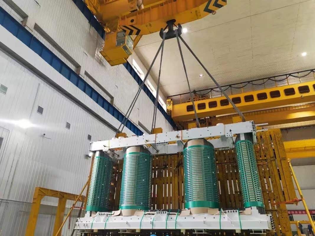
Understanding the Structure: Why Shell-Type Transformers Are Different
Before diving into applications, it’s vital to understand what differentiates shell-type transformers structurally. In shell-type transformers, the windings are surrounded by the core material on both sides (as opposed to being wrapped around the core in core-type transformers). This encapsulation leads to:
- Improved magnetic coupling and flux control
- Lower leakage reactance
- Higher short-circuit withstand capacity
- Better mechanical strength of windings
These structural advantages are foundational to their specialized applications.
Applications Across Industries: Where Shell-Type Transformers Excel
Let’s explore where these transformers are not just used — but required — due to their distinctive properties.
1. Railway Electrification and Traction Systems
In high-speed railway or metro systems, voltage fluctuation and high starting currents are the norm. Traction substations need equipment that can:
- Handle frequent overloads
- Resist vibration and environmental stress
- Minimize energy losses
Shell-type transformers are often used in traction converter stations or rail-side transformers due to their high short-circuit strength and low leakage inductance.
Key Performance Attributes in Traction Use:
| Attribute | Requirement | Shell-Type Performance |
|---|---|---|
| Overload Handling | High | Excellent |
| Short-Circuit Resistance | Critical | Outstanding |
| Compact Installation | Preferred | Compact Design |
| Harmonic Filtering | Needed | Moderate to Good |
2. Power Electronics and Converter Transformer Systems
In rectifier and inverter circuits (e.g., in renewable energy or DC transmission systems), transformers are exposed to harmonic-rich currents, which generate substantial heating and stress.
Shell-type transformers, with their enclosed winding configuration and magnetic symmetry, provide:
- Better harmonic current tolerance
- Lower hot-spot temperatures
- More uniform flux distribution
They are thus standard in:
- HVDC converter transformers
- Wind/solar inverter interface transformers
- Furnace and welding equipment
Harmonic Stress Resistance Comparison
| Transformer Type | Harmonic Tolerance | Heat Dissipation | Mechanical Stability |
|---|---|---|---|
| Shell-Type | High | Efficient | Very Strong |
| Core-Type | Moderate | Moderate | Weaker |
3. Large-Capacity Industrial Transformers
In steel mills, mining operations, or chemical plants, large equipment often draws thousands of amperes and operates under tough conditions. Shell-type transformers here are used in:
- Arc furnaces
- Rolling mill drives
- Compressor stations
Because of:
- Excellent short-circuit resistance
- High reliability in hot/dusty environments
- Better isolation and compact footprint
Real-World Case Study: Arc Furnace Transformer Use
In a South Asian steel plant, the use of a 60 MVA shell-type transformer increased uptime by 27%, reduced failure rates from arcing, and allowed tighter harmonic control. The plant reported annual energy savings of 3.5%.
4. Urban and Underground Substations
Shell-type transformers are also favored in underground substations and urban grid centers where:
- Compact design is essential
- Electromagnetic shielding is required
- Heat needs to be dissipated efficiently
Their magnetic symmetry and enclosed winding help limit electromagnetic interference — critical for areas with high electronic equipment density.
Urban Application Needs & Shell-Type Capability Table
| Urban Requirement | Shell-Type Transformer Response |
|---|---|
| Compact installation | Excellent |
| Electromagnetic interference | Minimal |
| Low noise operation | High |
| Fire safety (oil vs dry) | Compatible with dry-type models |
5. Marine and Offshore Installations
Shell-type transformers are increasingly found in offshore oil platforms, naval ships, and submarines due to:
- Compactness
- Vibration resistance
- High electrical isolation
Special dry-type shell designs offer improved safety, corrosion resistance, and thermal efficiency in these critical, high-risk environments.
Comparative Analysis: Shell-Type vs. Core-Type Transformers
| Feature | Shell-Type Transformer | Core-Type Transformer |
|---|---|---|
| Winding Support | Fully enclosed (high support) | Partially supported |
| Short-Circuit Strength | High | Moderate |
| Leakage Flux | Low | Higher |
| Size for Same Rating | Slightly larger | Compact |
| Harmonic Resistance | Better | Weaker |
| Cost | Higher | Lower |
| Maintenance Accessibility | Lower | Easier |
Engineering Considerations When Specifying Shell-Type Transformers
When selecting a shell-type transformer, engineers must evaluate the following:
- Voltage and current harmonics profile
- Short-circuit level and protection requirements
- Installation constraints (e.g., urban underground, offshore)
- Noise and EMI sensitivity of surrounding environment
- Long-term reliability and MTBF (Mean Time Between Failure)
High voltage designs (up to 765 kV) are also available, particularly for interconnection substations or high-speed traction lines.
What Are the Advantages and Limitations of Shell-Type Transformers?
When choosing the right transformer type for your application, overlooking the trade-offs of shell-type transformers could lead to unexpected complications—such as size constraints, limited accessibility, or higher capital costs. On the flip side, when applied correctly, shell-type transformers bring unbeatable performance benefits in specific environments. The consequences of misunderstanding these pros and cons can result in poor ROI, reduced operational stability, or frequent maintenance cycles. This guide dissects both the advantages and limitations of shell-type transformers to help you make an informed engineering decision.
Shell-type transformers offer superior short-circuit strength, better control over magnetic flux, and enhanced mechanical rigidity, making them ideal for high-power and harmonic-sensitive environments. However, they come with limitations such as bulkier construction, higher manufacturing cost, and more complex maintenance access due to their enclosed design.
Understanding these advantages and limitations can help engineers and decision-makers optimize transformer selection based on application-specific demands. Let’s break down where these transformers perform best—and where they fall short.
Shell-type transformers are always more efficient than core-type transformers.False
Efficiency depends on design and application. While shell-type transformers offer better short-circuit strength and flux control, core-type transformers may offer better efficiency in certain lower-power or standard grid applications.
Core Advantages of Shell-Type Transformers
Shell-type transformers provide a number of structural and operational advantages that are highly sought-after in specific applications:
1. Superior Short-Circuit Strength
Thanks to their unique winding structure—sandwiched between two core limbs—the windings are mechanically braced and shielded from displacement during electrical faults. This makes them especially suitable for:
- Traction substations
- Arc furnaces
- Converter transformers
Short-Circuit Performance Comparison
| Transformer Type | Short-Circuit Withstand (kA) | Mechanical Stress Resistance |
|---|---|---|
| Shell-Type | 50–120 | Very High |
| Core-Type | 30–80 | Moderate |
2. Better Control of Leakage Flux and EMI
Shell-type construction inherently encloses the magnetic circuit, which:
- Minimizes stray magnetic fields
- Enhances electromagnetic shielding
- Reduces risk of coupling to nearby sensitive equipment
This is critical in data centers, medical environments, or substations in dense urban areas.
3. Enhanced Mechanical Rigidity
With core limbs on both sides of the windings, the windings experience less physical deformation during voltage spikes or system faults. This structural symmetry results in:
- Longer service life
- Better reliability under shock/vibration
- Greater thermal stability
4. Improved Heat Distribution
Enclosed windings promote more uniform heat transfer, especially in shell-type dry transformers used in marine and industrial environments. This reduces hot-spot temperatures and aging of insulation.
5. Compact and Modular Designs for Special Applications
Although generally heavier, shell-type transformers can be designed in modular forms (e.g., for naval, offshore, or underground urban settings) to:
- Save lateral space
- Allow vertical stacking
- Fit into sealed or explosion-proof enclosures
Recognized Limitations of Shell-Type Transformers
While highly robust, shell-type transformers have some limitations that must be accounted for during planning and deployment:
1. Larger and Heavier Design
Due to the added core limbs and cladding, shell-type transformers tend to be:
- Heavier per kVA
- Bulkier in footprint
- Harder to transport and install
Size & Weight Comparison Table
| Specification | Shell-Type Transformer | Core-Type Transformer |
|---|---|---|
| Volume (for 10 MVA) | ~1.2× Core-Type | Baseline |
| Weight (dry type) | ~1.3× Core-Type | Baseline |
| Floor Load | Higher | Lower |
2. Complex Assembly and Maintenance
Due to their enclosed windings and dual-limb structure, shell-type transformers:
- Require more precise coil alignment
- Are harder to disassemble for repairs
- Need skilled technicians for maintenance
This increases both capital and operating costs.
3. Higher Manufacturing Costs
Extra materials (core steel, bracing), and complex winding design contribute to:
- ~10–25% higher unit cost
- Longer production lead times
- More specialized tooling requirements
Shell-type transformers cost less to produce than core-type transformers.False
Shell-type transformers generally cost more due to the complexity of core and winding arrangements, and the additional materials used.
4. Reduced Cooling Accessibility
Because windings are enclosed within the core window, cooling ducts are more restricted. In high-load or continuous operation environments, forced cooling systems are often mandatory.
Cooling Effectiveness Index
| Parameter | Shell-Type | Core-Type |
|---|---|---|
| Natural Air Cooling | Moderate | Better |
| Forced Air Cooling | Good | Good |
| Liquid Cooling Access | Limited | Flexible |
5. Longer Repair Downtime
In the event of a fault:
- Winding access is more difficult
- Core limb removal may be necessary
- Rewinding requires re-balancing the core field
This makes shell-type transformers more suited to mission-critical environments where failure probability is minimized by robust design—not easily mitigated after-the-fact.
Summary Chart: Advantages vs Limitations
| Category | Advantages | Limitations |
|---|---|---|
| Short-Circuit Performance | Excellent mechanical strength | — |
| EMI/Flux Control | Low leakage, better shielding | — |
| Mechanical Stability | Windings fully supported | — |
| Heat Distribution | Uniform, reduces insulation wear | Harder to cool naturally |
| Size and Weight | Compact in some vertical designs | Generally heavier and bulkier |
| Maintenance | Stable under load | Difficult and expensive to service |
| Cost | Longer lifespan in demanding systems | Higher upfront and manufacturing cost |
| Application Scope | Ideal for industrial and special installations | Not ideal for general utility-scale distribution |
Conclusion
Shell-type transformers offer a robust alternative to core-type designs, particularly in environments with high mechanical stress and power requirements. Their unique structure enhances magnetic performance and winding protection, making them essential in specific industrial and power system applications. By understanding their characteristics and trade-offs, engineers and operators can make informed decisions in transformer selection and deployment.
FAQ
Q1: What is a shell-type transformer?
A1: A shell-type transformer is a type of transformer where the magnetic core surrounds the windings, forming a shell-like structure. In this design:
The windings are placed on the central limb,
While the side limbs complete the magnetic circuit,
This configuration provides better protection, low leakage reactance, and superior short-circuit strength, making it ideal for high-voltage and industrial applications.
Q2: How is the core structure different from a core-type transformer?
A2: The main difference lies in the magnetic circuit design:
In a core-type transformer, the windings surround the core limbs.
In a shell-type transformer, the core surrounds the windings.
This results in:
Two magnetic paths in shell-type vs. one in core-type
Compact design and better mechanical support in shell-type
Higher efficiency under short-circuit conditions
Shell-type is often used where space, strength, and fault tolerance are priorities.
Q3: What are the advantages of shell-type transformers?
A3: Shell-type transformers offer:
Higher mechanical strength to withstand fault forces
Better short-circuit performance due to magnetic flux control
Reduced leakage reactance, enhancing voltage regulation
Compact and symmetrical design, which improves heat distribution
They are widely used in rectifier transformers, electric furnaces, and large industrial power supplies.
Q4: Are there any disadvantages to using shell-type transformers?
A4: Yes, shell-type transformers have some limitations:
Complex manufacturing and higher cost due to intricate core and winding layout
More insulation required between layered windings
Heavier and bulkier than core-type in some cases
They are not always ideal for standard distribution applications where cost and simplicity are more critical.
Q5: Where are shell-type transformers commonly used?
A5: You’ll often find shell-type transformers in:
High-power industrial applications (e.g., steel mills, smelters)
Traction systems (e.g., railway substations)
Converter and rectifier stations
High-voltage lab equipment
Their durability, energy efficiency, and short-circuit resistance make them ideal for mission-critical installations.
References
Electrical4U: Shell-Type Transformer Explained
https://www.electrical4u.com/shell-type-transformer/
IEEE C57.12.10: Standard for Power Transformers
https://standards.ieee.org/standard/C57_12_10-2017.html
Doble Engineering: Transformer Core Design and Testing
https://www.doble.com/solutions/core-analysis/
NPTEL: Transformer Core Design Video Lecture
https://nptel.ac.in/courses/108/105/108105053
ScienceDirect: Performance Analysis of Shell-Type Transformers
https://www.sciencedirect.com/science/article/pii/S187661021731018X