Transformers are essential components in electrical power systems, and they are broadly categorized into two types based on their insulation and cooling method: dry-type and wet-type (commonly referred to as oil-immersed transformers). Identifying whether a transformer is wet or dry is crucial for maintenance planning, environmental considerations, and operational safety. This guide outlines the key ways to distinguish between these two types.
What Is the Difference Between Wet and Dry Transformers?
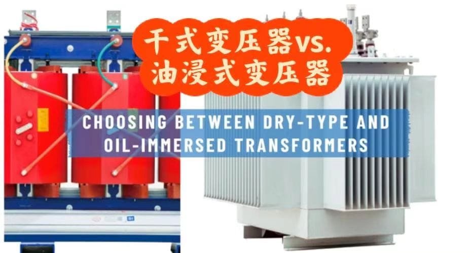
Selecting the wrong transformer type—wet or dry—can expose your electrical system to performance issues, safety hazards, or inflated maintenance costs. For instance, using a wet transformer in a fire-risk zone or a dry transformer in a moisture-rich environment can lead to rapid degradation or catastrophic failure. This confusion arises frequently during project planning, especially when teams don’t fully understand what distinguishes wet (oil-filled) from dry-type transformers. This article defines both types, compares their applications, and explains how to choose the right one.
A wet transformer, also known as an oil-filled transformer, uses insulating oil for both cooling and insulation, while a dry transformer uses air or solid dielectric materials instead of liquid. Wet transformers are suited for outdoor and high-capacity applications, whereas dry transformers are typically used indoors or in fire-sensitive environments due to their non-flammable insulation.
Knowing the differences between these two types is critical to aligning transformer performance with safety, reliability, and operational cost. Let’s walk through the structural, functional, and environmental differences so you can choose confidently.
Dry transformers can be safely installed indoors without fire hazards.True
Dry transformers use non-flammable insulation materials, making them suitable and safe for indoor installations, particularly in fire-sensitive areas.
Wet Transformers (Oil-Filled): Definition and Characteristics
What is a Wet Transformer?
A wet transformer, or oil-filled transformer, is filled with insulating mineral oil or synthetic esters. This oil serves two purposes:
- Dielectric insulation between live parts
- Heat dissipation through convection and radiation
These transformers are hermetically sealed or designed with conservator tanks and are cooled by:
- ONAN: Oil Natural Air Natural
- ONAF: Oil Natural Air Forced
- OFAF: Oil Forced Air Forced
- OFWF: Oil Forced Water Forced
Key Properties of Wet Transformers
- Excellent cooling efficiency
- Higher power capacity (up to 1000 MVA+)
- Lower size-to-power ratio
- Requires fire safety zones if installed indoors
- Needs periodic oil testing and maintenance
Common Applications:
| Sector | Usage Example |
|---|---|
| Power Utilities | Grid substations, HV transmission |
| Renewable Energy | Solar & wind substations |
| Heavy Industry | Steel plants, oil & gas, mining |
| Urban Outdoor Systems | Underground vault installations |
Dry Transformers: Definition and Characteristics
What is a Dry Transformer?
A dry transformer does not use any liquid for insulation or cooling. Instead, it relies on:
- Air cooling through natural or forced convection
- Solid insulation such as resin (in cast resin transformers) or varnish
They are safer for indoor and enclosed installations due to non-flammable properties.
Types of Dry Transformers:
- Cast Resin Transformer (CRT)
- VPI (Vacuum Pressure Impregnated) Transformer
- Open-wound ventilated units
Key Properties of Dry Transformers
- Environmentally safer — no oil leaks
- Requires less maintenance
- Slightly less efficient cooling than oil-filled types
- Limited to medium power ratings (up to \~30 MVA)
- Operates with higher sound levels in some designs
Typical Applications:
| Sector | Usage Example |
|---|---|
| Commercial Buildings | Indoor panels, distribution networks |
| Hospitals/Labs | Fire-rated zones |
| Data Centers | Low-EMI indoor environments |
| Marine/Navy | Fireproof naval transformer rooms |
Comparison Table: Wet vs. Dry Transformers
| Feature | Wet Transformer (Oil-Filled) | Dry Transformer |
|---|---|---|
| Insulation Medium | Mineral oil or synthetic esters | Air or solid epoxy resin |
| Cooling Method | Oil + air/water | Natural or forced air |
| Fire Risk | Moderate to High | Very Low |
| Environmental Safety | Risk of oil leakage | Environmentally clean |
| Power Capacity Range | Up to 1000 MVA+ | Up to \~30 MVA |
| Maintenance Requirements | High (oil testing, filtration) | Low (visual inspection, dusting) |
| Installation Location | Outdoors or fire-safe zones | Indoors or high-risk fire zones |
| Size | More compact for same rating | Bulkier for equivalent rating |
| Cooling Efficiency | Higher due to oil properties | Lower — requires more ventilation |
| Noise Level | Lower (due to oil dampening) | Higher (especially in VPI types) |
| Cost (Initial) | Moderate to High | High for resin type |
| Life Expectancy | 25–35 years | 15–25 years |
Wet transformers are safer for indoor use than dry transformers.False
Wet transformers use flammable liquids like mineral oil, which pose a fire risk in enclosed indoor spaces, unlike dry transformers that use non-flammable materials.
Selection Guidelines: When to Choose Wet or Dry Type?
Choose a Wet Transformer When:
- High voltage or power (>30 MVA) is required
- Installation is outdoor or underground vault
- Thermal performance and compactness are critical
- There’s space and fire protection infrastructure available
- The transformer will experience heavy or continuous load
Choose a Dry Transformer When:
- Installation is indoor or close to human activity
- Fire safety is a top concern
- Environmental regulations prohibit oil
- Low maintenance and visual inspection are desired
- Power rating is within medium-range (<30 MVA)
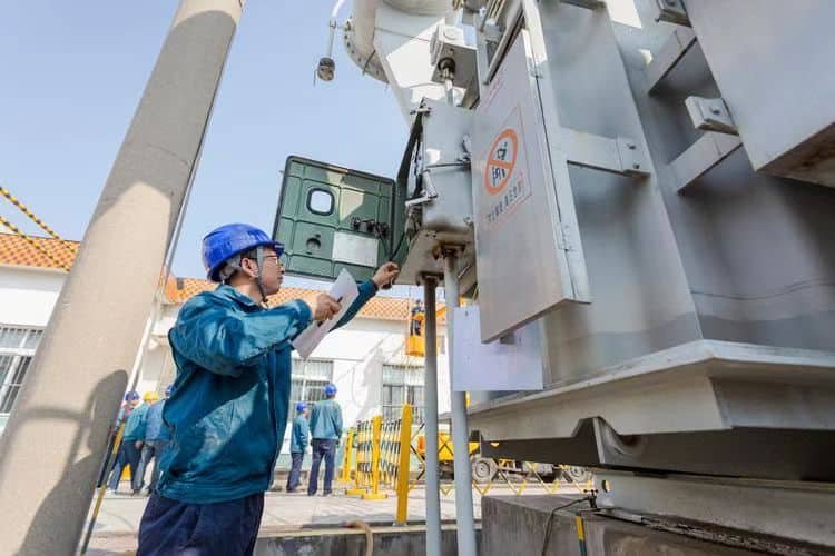
What Should Be Checked During a Visual Inspection of a Transformer?

Neglecting proper visual inspection of transformers—whether dry or wet type—can lead to the unnoticed progression of critical faults such as oil leaks, bushing cracks, corrosion, or overheating. Left unchecked, these issues often result in catastrophic failures, long outages, or safety hazards. Routine visual inspections, though seemingly simple, play a vital role in early fault detection, operational safety, and asset longevity. This article outlines exactly what you should check during a visual inspection of a transformer and how to perform it effectively.
A visual inspection of a transformer should check for oil leaks, corrosion, deformation, discoloration, unusual odors, physical damage, label integrity, grounding continuity, cooling system condition, and signs of overheating or insulation failure. It is a non-invasive, first-line maintenance step that ensures early fault detection and safe operation.
Even the most advanced monitoring systems can’t replace the human eye for spotting early warning signs. Read on for a complete checklist, tools needed, safety practices, and inspection intervals based on transformer type and rating.
Visual inspection is only necessary for old transformers.False
Visual inspection is essential for all transformers regardless of age, as environmental stress, load variation, and mechanical impact can affect any unit over time.
Why Visual Inspection Is Critical for All Transformers
Visual inspection is the first and most frequent maintenance action in transformer lifecycle management. It helps identify:
- Progressive deterioration (e.g., rust, seal damage)
- Immediate failure threats (e.g., oil leaks, bushing cracks)
- Environmental effects (e.g., UV damage, water ingress)
- Operational anomalies (e.g., overheating, abnormal noise)
This is particularly important for:
- Critical load-bearing transformers
- Outdoor oil-filled transformers exposed to weather
- Dry-type indoor transformers exposed to dust or moisture
- Units without online monitoring systems
Comprehensive Visual Inspection Checklist
The table below summarizes a structured checklist based on transformer components and observed parameters:
| Inspection Area | What to Check |
|---|---|
| Oil Level & Quality | Oil level in gauge; signs of milky, discolored, or oxidized oil |
| Bushings | Cracks, chips, flashover marks, dirt accumulation, oil seepage |
| Tank Body & Frame | Rust, paint peeling, denting, signs of overheating or deformation |
| Cooling System | Fans, radiators, fins, pumps—look for blockages, leaks, or broken components |
| Gaskets & Seals | Oil seepage, swelling, or degradation |
| Grounding | Ground wire intact, no corrosion at grounding lug or clamp |
| Conservator (if present) | Oil level, air bladder condition, breather silica gel color |
| Tap Changer Panel | Cleanliness, secure mounting, no burnt odor or discoloration |
| Breather Unit | Silica gel should be blue (not pink); inspect for clogging |
| Nameplate & Labels | Legibility of voltage, power rating, manufacturer info, and serial number |
| Wiring & Cables | Insulation cracking, loose terminations, arcing signs |
| Ventilation Louvers | Free from blockages, vermin infestation, or obstruction |
| Surrounding Area | Vegetation clearance, oil containment pits, fire safety distance |
Silica gel in transformer breathers turns pink when it is saturated with moisture.True
Silica gel is typically blue when dry and turns pink when saturated, indicating the need for replacement or regeneration.
Tools and Safety Gear Needed
To conduct a proper transformer visual inspection, equip your team with the following:
| Tool / Equipment | Purpose |
|---|---|
| Insulated gloves & boots | Electrical safety |
| Infrared thermometer | Detect overheating or hotspot areas |
| Inspection flashlight | Better visibility in tank corners or cabinets |
| Camera or mobile device | Visual documentation and comparisons |
| Cleaning cloth / brushes | Remove dust to inspect small components |
| Binoculars | For viewing tall transformers or components |
| Logbook or checklist sheet | Record all observations systematically |
Safety Note: Always de-energize when possible. If inspection must be done live, maintain minimum approach distances according to your local regulations (e.g., OSHA, IEC, NFPA 70E).
Visual Indicators of Fault or Imminent Failure
Pay close attention to the following red flags during inspection:
- Oil leak beneath the unit: Indicates gasket failure or tank crack
- Discolored paint near bushings: Sign of corona or localized overheating
- Bulging tank walls: Gas buildup due to insulation breakdown
- Pink silica gel in breather: Moisture saturation—replace or regenerate
- Burning odor: Possible internal arcing or insulation failure
- Flashover marks on bushings: Indicates prior or imminent dielectric failure
- Condensation or dust on dry transformer coils: Leads to tracking and insulation degradation
Frequency of Visual Inspections
| Transformer Type | Recommended Inspection Interval |
|---|---|
| Outdoor Oil-Filled | Weekly or Biweekly |
| Indoor Dry-Type | Monthly |
| Critical Power Units | Daily (quick walk-around) |
| After Storm/Disturbance | Immediate visual recheck |
Always log each inspection event even if no issues are found. This builds a trendline for proactive maintenance.
Visual inspections eliminate the need for thermographic or electrical testing.False
While visual inspections detect many surface-level issues, they must be complemented by thermography, dissolved gas analysis (DGA), insulation resistance tests, and other diagnostic tools for complete transformer health assessment.
How Should Cooling and Ventilation Be Designed for Transformers?
Transformer overheating is one of the most common causes of electrical equipment failure. Whether due to ambient temperature rise, poor ventilation planning, or overloaded operation, thermal stress deteriorates insulation, reduces lifespan, and increases fire risk. The failure to design a suitable cooling and ventilation system can cause premature transformer breakdown and unsafe operating conditions. This guide provides a detailed, engineering-focused explanation of how transformer cooling and ventilation should be properly designed for optimal thermal management and reliability.
Cooling and ventilation for transformers must be designed based on transformer type, rated power, ambient temperature, enclosure type, and installation environment. Wet (oil-filled) transformers use oil and air/water cooling combinations, while dry-type transformers rely on natural or forced air circulation. Key considerations include cooling class (ONAN, ONAF, AN, AF), airflow design, heat dissipation paths, ambient airflow patterns, and minimum clearance requirements to ensure safe thermal operation.
Improper ventilation or undersized cooling systems can turn an otherwise reliable transformer into a liability. Let's break down the essentials of effective cooling system design, tailored for both dry-type and wet transformers.
Transformer overheating can be prevented solely by relying on natural convection.False
Natural convection may be insufficient for higher-rated transformers, especially in enclosed or high-temperature environments. Forced air or liquid cooling systems are often necessary to manage heat effectively.
Key Factors Influencing Cooling and Ventilation Design
Designing an effective transformer cooling and ventilation system involves multiple interdependent parameters:
| Design Parameter | Description |
|---|---|
| Transformer Type | Dry-type (AN, AF) vs. oil-filled (ONAN, ONAF, OFAF, etc.) |
| Power Rating (kVA/MVA) | Higher ratings require more robust cooling |
| Ambient Temperature | Influences margin between operating and thermal limit |
| Altitude | Affects air density and cooling efficiency |
| Enclosure/Ventilation | Impacts air movement and heat extraction |
| Duty Cycle | Continuous, intermittent, or cyclic loading patterns |
| Safety/Noise Constraints | May restrict the use of fans or exhaust systems |
Cooling capacity must increase with transformer load.True
As the electrical load increases, more current flows through windings, generating higher heat levels. The cooling system must scale accordingly to maintain safe operating temperatures.
Transformer Cooling Classes Explained
Cooling classes define how heat is removed from the transformer core and windings. Here's an overview:
For Oil-Filled (Wet) Transformers
| Cooling Class | Expansion | Description |
|---|---|---|
| ONAN | Oil Natural, Air Natural | Passive cooling using oil circulation and ambient air |
| ONAF | Oil Natural, Air Forced | Adds fans for air-side cooling |
| OFAF | Oil Forced, Air Forced | Adds oil pumps and air blowers |
| OFWF | Oil Forced, Water Forced | High-capacity cooling using water heat exchangers |
For Dry-Type Transformers
| Cooling Class | Expansion | Description |
|---|---|---|
| AN | Air Natural | Self-cooled by natural air convection |
| AF | Air Forced | Uses fans or blowers to increase heat extraction |
| AA/FA | Air-Auto/Forced Air | Fan cooling triggered when temperature exceeds preset limit |
Engineering Design: Cooling for Oil-Filled Transformers
Oil-filled transformers require thermal pathways that move heat from the windings to the external surface, then to the surrounding environment.
Typical Cooling Design Components
- Radiators or Fins: Increase surface area for air contact
- Oil Pumps (in OFAF systems): Circulate insulating oil through heat exchangers
- Cooling Fans: Mounted near radiators for heat dissipation
- Cooling Water System: Used in high-capacity power transformers
- Temperature Sensors & Alarms: Monitor top-oil and winding temperatures
- Conservator Tank: Accommodates oil volume changes during heating/cooling
Oil Circulation Path Diagram:
| Step | Description |
|---|---|
| 1 | Heat generated in windings |
| 2 | Oil absorbs heat and rises to the top |
| 3 | Oil moves through radiators (ONAN) or is pumped |
| 4 | Air or water removes heat from radiator surface |
| 5 | Cooled oil returns to the bottom of the transformer |
Engineering Design: Cooling for Dry-Type Transformers
Dry-type transformers depend entirely on air for heat removal, requiring strategic airflow management and thermal insulation.
Typical Cooling Design Components
- Cooling Ducts: Built-in gaps between windings for airflow
- Heat Sinks: Fins on coils to increase convection
- Fans: Forced air systems switch on when thresholds are exceeded
- Thermal Sensors: Embedded RTDs or thermocouples in windings
- Air Filters or Louvers: Prevent dust and vermin entry while allowing flow
Airflow Design Considerations:
| Parameter | Ideal Value or Range |
|---|---|
| Clearance from Wall (rear) | ≥ 30–60 cm |
| Ventilation Grill Area | ≥ 150% of transformer top surface area |
| Air Velocity (forced) | 3–6 m/s across coils |
| Temperature Rise Limit | 80°C for Class H insulation |
Ventilation Design for Transformer Rooms and Enclosures
Room-level thermal management is just as important as transformer-internal cooling. Without proper air exchange, the ambient temperature rises and reduces cooling effectiveness.
Key Ventilation Design Guidelines
| Design Parameter | Specification |
|---|---|
| Air Exchange Rate | Minimum 6–12 air changes/hour (adjusted for load and number of units) |
| Temperature Monitoring | Install sensors at high and low points in room |
| Airflow Direction | Bottom to top or front to rear |
| Vent Opening Area | ≥ 1.5–2.0 times transformer frontal area |
| Fan Activation Temp | 45–55°C ambient or 90°C winding (dry type) |
| Noise Levels | Use silencers or dampers if in commercial/residential buildings |
Transformer Room Layout Sketch Example:
| Feature | Description |
|---|---|
| Inlet Louvers (Low) | Allow cool air entry |
| Exhaust Fans (High) | Remove hot air |
| Heat Detectors | Activate ventilation or alarms |
| Separated Compartments | Reduce hotspot accumulation |
| Fire-rated Panels | Comply with building codes |
Practical Design Example: 2 MVA Dry-Type Transformer in Indoor Facility
Assumptions:
- Transformer Rating: 2 MVA, Class F insulation
- Room Size: 6m x 5m x 3m (90 m³)
- Cooling Method: Air Natural (AN), Fan-assisted (AF as backup)
Design Outcomes:
| Element | Value |
|---|---|
| Cooling Duct Size | 50 mm between coils |
| Fan Activation Temp | 90°C (top coil), via embedded RTD |
| Room Air Exchange Rate | 12 changes/hour → 18 m³/min ventilation |
| Louvers & Grills | 1.5 m² opening with dust screens |
| Clearance from Walls | ≥ 600 mm on all sides |
| Emergency Cutoff System | Shuts down fans at 120°C overheat |
What Information Should Be Included on a Transformer Label and Nameplate?
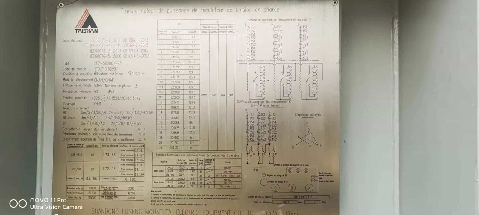
Failure to check or understand a transformer's label and nameplate information can lead to costly mistakes — from connecting incompatible systems to exceeding rated limits, causing overheating, dielectric breakdown, or even complete transformer failure. The nameplate is not just an identification tag — it's a critical component of operational safety and performance management. This article explains everything that must be included on a transformer nameplate and labeling system, why each detail matters, and how to interpret them correctly for both dry-type and oil-filled transformers.
A transformer nameplate must include key technical specifications such as rated power (kVA/MVA), primary and secondary voltage, frequency, phase, vector group, impedance, temperature rise, insulation class, cooling method, serial number, manufacturer, standard compliance, and connection diagrams. Labels should also include safety warnings, terminal designations, and grounding information. These details ensure proper installation, compatibility, maintenance, and regulatory compliance.
A missing or inaccurate nameplate can invalidate warranties, violate regulations, or lead to incorrect installation. Read on to explore detailed tables, diagrams, and real-world examples of proper transformer labeling practices.
All transformers have the same nameplate data regardless of type or rating.False
Transformer nameplate data varies depending on design, power rating, cooling method, insulation class, and national standards. Different transformer types require different data points.
Why Transformer Nameplate Information Matters
The nameplate is the primary source of engineering data that defines:
- Electrical compatibility with your power system
- Thermal limits to prevent insulation failure
- Physical configuration for installation and wiring
- Regulatory conformance for safety inspections
- Maintenance schedules and parts identification
Without this information, technicians are essentially operating “blind,” increasing the risk of overload, arcing, or system damage.
Standard Nameplate Data (Dry & Wet Transformers)
The following table shows the standard transformer nameplate data as per IEC 60076 and ANSI C57.12:
| Parameter | Description |
|---|---|
| Manufacturer Name | OEM and plant location |
| Serial Number | Unique identifier used for service records and warranty |
| Year of Manufacture | Indicates service life and insulation aging |
| Rated Power | kVA or MVA capacity at nominal temperature |
| Rated Frequency | Typically 50 Hz or 60 Hz |
| Rated Voltage (HV/LV) | Nominal input/output voltages in volts or kV |
| Connection Symbol/Vector Group | Indicates winding configuration and phase shift (e.g., Dyn11, Yyn0) |
| Impedance (%) | Per-unit impedance, important for fault analysis |
| Cooling Method | AN, AF, ONAN, ONAF, etc. |
| Insulation Class | e.g., Class A, B, F, H — defines temperature withstand capability |
| Temperature Rise Limit | e.g., 55°C, 65°C — maximum allowed above ambient |
| Tapping Range / Tap Changer | Voltage adjustment capability (±2.5%, ±5%, etc.) |
| Weight | Core, tank, and total assembly |
| Oil Volume (if applicable) | For oil-filled types |
| Cooling Surface Area | Helps calculate ventilation for placement |
| No-Load and Load Losses | Measured losses at factory (W or kW) |
| Efficiency Data | Efficiency at various loads |
| Sound Level (dB) | Especially for urban or commercial installations |
| Standard Compliance | IEC, ANSI, IEEE, BIS, GB standards adhered to |
| Wiring Diagram | HV and LV terminal markings (usually schematic or vector diagram included) |
| Safety Symbols | Voltage, fire risk, earth ground, isolation warnings |
A transformer’s impedance value listed on the nameplate affects system fault levels.True
Transformer impedance affects short-circuit currents and voltage regulation. It's critical for fault coordination and protection system design.
Labeling Elements Beyond the Nameplate
While the nameplate holds primary technical data, other labels on the transformer are also essential:
1. Terminal Labels
| Label | Description |
|---|---|
| H1, H2, H3 | High-voltage winding terminals |
| X1, X2, X3 | Low-voltage winding terminals |
| T1–T6 | Tapping terminals (if present) |
| G or GND | Ground terminal |
These are usually embossed, engraved, or printed on metallic or polymer tags near the connection lugs.
2. Safety and Hazard Labels
| Symbol | Meaning |
|---|---|
| ⚡ | High Voltage Warning |
| ♻️ | Eco-design, recyclable oil (if stated) |
| 🔥 | Fire risk — especially for oil-filled |
| 🛠️ | Maintenance panel warning |
3. Cooling System Tags
Oil-filled units may include:
- Fan number labels
- Pump indicator labels
- Radiator module IDs
- Oil level indicators (marked FULL, MIN, MAX)
4. Tap Changer Labels
Manual or motor-operated tap changers include:
- Tap position labels (e.g., +2, +1, 0, -1, -2)
- Operation direction arrows
- Voltage ranges per tap
Sample Nameplate Layout (Illustrated Breakdown)
| Field | Example Value |
|---|---|
| Manufacturer | ProVolt Transformers Ltd. |
| Serial Number | TRX-2023-000781 |
| Power Rating | 2000 kVA |
| Frequency | 50 Hz |
| Voltage (HV/LV) | 11 kV / 0.415 kV |
| Vector Group | Dyn11 |
| Insulation Class | Class F |
| Temp Rise | 65°C |
| Cooling | AN/AF |
| Impedance | 6.5% |
| Tap Range | ±5% in 2.5% steps |
| Standard | IEC 60076 |
| Weight | 2750 kg (total) |
| No-Load Losses | 1.5 kW |
| Load Losses | 12.8 kW |
The vector group displayed on a transformer nameplate indicates the relative phase shift between primary and secondary windings.True
The vector group (e.g., Dyn11) provides critical information on winding connection and phase displacement, essential for parallel operation and system design.
Compliance and Regulatory Considerations
Transformers installed in commercial or industrial environments must comply with various labeling and marking requirements:
| Standard | Labeling Requirement |
|---|---|
| IEC 60076 | Mandatory fields include voltage, frequency, impedance, power rating |
| ANSI C57 | Specifies nameplate format, insulation class, connection symbols |
| ISO/IEC 17025 | Calibration traceability for loss measurements |
| CE / UL / BIS | Must include safety and certification labels |
| RoHS/Reach | For environmental compliance |
Failure to comply can result in failed inspections, denied grid connection approvals, or legal liability after equipment failure.
What Should Be Considered When Choosing a Transformer Installation Environment?
Improper transformer installation can severely compromise system performance, safety, and asset longevity. Failing to evaluate the environmental conditions—such as humidity, dust levels, altitude, vibration, and ambient temperature—can lead to overheating, corrosion, insulation degradation, or even catastrophic failure. Many transformer failures are directly linked to unsuitable site selection or unmitigated environmental risks. The good news? Selecting the right installation environment tailored to transformer type and duty profile dramatically improves reliability and operational safety. This article outlines the key environmental factors that must be considered when planning transformer installations—whether indoors, outdoors, industrial, or marine environments.
A transformer’s installation environment must be chosen based on ambient temperature, humidity, pollution level, enclosure type, ventilation, seismic activity, altitude, and accessibility for maintenance. Indoor installations suit dry-type transformers in clean, fire-sensitive spaces, while oil-filled transformers are typically installed outdoors or in purpose-built vaults with fire mitigation measures. Site-specific considerations such as flood risk, cooling airflow, and electromagnetic interference must also be addressed.
Proper site planning is the foundation of transformer performance and safety. Let’s break down the critical environmental criteria and best practices for transformer installation across different settings.
All transformers can be installed outdoors with minimal protection.False
Only oil-filled transformers designed for outdoor use can operate safely in open environments. Dry-type transformers and indoor-rated units require protective enclosures and may fail when exposed to moisture, dust, or extreme temperatures.
Key Environmental Factors for Transformer Installation
| Environmental Factor | Impact on Transformer Performance |
|---|---|
| Ambient Temperature | Affects cooling and insulation life; requires derating above 40°C |
| Humidity / Moisture | Can degrade insulation in dry-type transformers; causes corrosion in wet types |
| Pollution & Dust | Leads to tracking, overheating, reduced cooling, fire hazard |
| Altitude | Air density drops above 1000m → reduced cooling → derating required |
| Vibration/Shock | May cause mechanical stress or coil loosening in poorly braced units |
| Seismic Zone | Requires reinforced mounting, anchoring, seismic-certified design |
| EMI/EMF Proximity | May require shielding or grounding considerations near sensitive equipment |
| Fire Hazard Zone | Determines insulation class and enclosure type |
| Access & Maintainability | Affects servicing safety, inspection ease, fault response time |
Indoor vs. Outdoor Installation: Suitability Comparison
| Feature | Indoor Installation | Outdoor Installation |
|---|---|---|
| Typical Transformer Type | Dry-type (cast resin or VPI) | Oil-filled (ONAN/ONAF/OFWF) |
| Fire Safety Requirement | High (often installed in fire-rated rooms) | Moderate (typically isolated outdoors) |
| Cooling Requirement | Forced ventilation or HVAC | Ambient airflow or forced cooling |
| Protection Needed | From moisture, dust, EMI | From rain, UV, animals, flood |
| Noise Constraint | High – use low-noise design | Moderate – can use standard fans |
| Accessibility | Easy with dedicated access points | May need fenced area or platform |
| Common Locations | Hospitals, malls, data centers, marine | Substations, solar plants, industries |
Indoor transformers can be installed without considering ventilation requirements.False
Indoor transformers, especially dry-type, still require proper ventilation to prevent overheating and maintain insulation life. Poor airflow can cause serious thermal stress.
Installation Environment by Transformer Type
1. Dry-Type Transformers (Cast Resin / VPI)
Best Suited For:
- Indoor rooms with clean air
- Hospitals, airports, malls, and commercial facilities
- Areas where oil-based systems are restricted
Key Requirements:
| Requirement | Specification |
|---|---|
| Ambient Temp. Limit | Typically 40°C; derate above |
| Humidity Tolerance | Max 95% (non-condensing) |
| Ventilation Needs | 6–12 air changes per hour in enclosed rooms |
| Fire Safety | Install in fire-resistant enclosure/room |
| Clearance | ≥300 mm side, ≥500 mm top for airflow |
| Seismic Compliance | Braced supports in seismic zones |
Common Failure Risks:
- Dust blocking cooling ducts
- Moisture absorption in high-humidity environments
- Overheating due to insufficient room ventilation
2. Oil-Filled Transformers (ONAN/ONAF/OFWF)
Best Suited For:
- Outdoor substations
- Industrial power distribution
- Renewable energy interconnections
- High-load power transmission
Key Requirements:
| Requirement | Specification |
|---|---|
| Ambient Temperature | -25°C to +50°C (design dependent) |
| Cooling System | Fans, radiators, or heat exchangers |
| Weather Protection | Canopy, fencing, lightning arresters |
| Oil Containment | Bund wall with 110% containment volume |
| Fire Separation Distance | ≥3 m from buildings (check local code) |
| Accessibility | Side and top access for conservator, bushings, etc. |
| Grounding | Dedicated earth pit with <1Ω resistance |
Common Failure Risks:
- Oil leaks from degraded gaskets
- Vegetation or rodents near live parts
- Flooding of oil containment pit
- Lightning damage due to improper earthing
High-Altitude, Marine, and Hazardous Area Installations
High Altitude (Above 1000m)
- Air becomes thinner → less cooling capacity
- Derate by \~0.5% for every 100m above 1000m
- May require forced-air or oil cooling for larger units
Marine/Offshore Use
- Prefer sealed dry-type or offshore-certified oil-filled transformers
- Enclosures must be IP55+ corrosion-resistant
- Wind-driven salt spray protection is critical
- Vibration damping mountings required for vessels
Hazardous / Explosive Atmospheres (e.g., ATEX zones)
- Use explosion-proof dry-type transformers
- Flameproof enclosures with anti-spark design
- All electrical terminals must be sealed and classified
Transformers designed for inland industrial use can be safely installed on ships without modification.False
Marine environments demand corrosion-resistant materials, sealed windings, anti-vibration design, and compliance with maritime electrical standards. Inland transformers are not suitable without customization.
Transformer Room Design (Indoor Installations)
| Element | Best Practice |
|---|---|
| Floor Loading | Ensure transformer weight does not exceed slab capacity |
| Drainage | Slope floor or install sump pump for any accidental spills |
| Ventilation | Use louvered doors or wall fans – keep temperature <40°C |
| Access Door Size | Sized to move transformer in/out without disassembly |
| Fire Safety | Install smoke/heat detectors, fire-rated walls and doors |
| EMC Shielding | Optional for sensitive adjacent electronics |
| Illumination | Bright, shadow-free lighting for maintenance |
| Security | Lockable room; signage for high-voltage area |
What Are the Key Safety and Maintenance Indicators for Transformers?
When safety and maintenance indicators on transformers are ignored or misunderstood, the consequences are often severe: electrical faults, unplanned outages, fire hazards, or irreversible equipment damage. Transformers—whether dry-type or oil-filled—must be continuously monitored through well-placed visual, mechanical, and electronic indicators. These indicators act as an early warning system, signaling when a transformer is under stress or nearing failure. Knowing what to look for, where to find it, and how to respond can mean the difference between a minor service call and a catastrophic shutdown.
Transformer safety and maintenance indicators include oil temperature gauges, winding temperature indicators, pressure relief devices, gas detectors, oil level gauges, breather color indicators, load meters, and fault annunciators. These are supported by protective relays, infrared thermography, dissolved gas analysis (DGA), and insulation resistance testing to monitor real-time health. Routine checks and digital monitoring reduce the risk of failure and extend transformer life.
These indicators are essential to condition-based maintenance strategies. Read on to learn how to interpret, track, and act upon transformer health signals—before faults happen.
Transformer safety indicators are only needed during commissioning or start-up.False
Safety indicators must be monitored throughout the transformer’s lifecycle to detect early signs of wear, overheating, gas buildup, or insulation degradation. Continuous observation is essential.
Categorizing Transformer Safety and Maintenance Indicators
To fully cover a transformer's condition, indicators are typically grouped into three main categories:
| Category | Function |
|---|---|
| Thermal Indicators | Monitor temperature of oil and windings |
| Mechanical Indicators | Monitor pressure, oil level, and physical status |
| Electrical & Gas Indicators | Monitor internal faults, gas generation, and load conditions |
1. Thermal Indicators
High temperatures are a leading cause of insulation degradation and failure. These devices detect and report rising heat levels.
Key Devices:
| Indicator | Description |
|---|---|
| Top Oil Thermometer | Measures oil temperature at the hottest point of the tank |
| Winding Temperature Indicator (WTI) | Uses current simulation to estimate the winding hot-spot |
| Infrared Scan Ports | Allow thermal cameras to check for heat anomalies without opening covers |
| Thermal Alarm Contacts | Trigger alarms if preset temperature limits are exceeded |
| RTD Sensors (Dry Type) | Precision resistive sensors embedded in windings or core |
Standard Limits:
| Parameter | Normal Operation | Alarm Limit | Trip Limit |
|---|---|---|---|
| Top Oil Temp (ONAN) | 40–55°C | 75°C | 85°C |
| Winding Hot Spot (Dry Type) | 60–80°C | 110°C | 120–130°C |
Winding temperature indicators only reflect ambient temperature.False
Winding temperature indicators simulate the internal conductor temperature using current-derived heat modeling, not just ambient conditions.
2. Mechanical Indicators and Safety Devices
Mechanical health indicators are mostly found on oil-filled transformers and address tank pressure, oil condition, and structural stability.
Essential Components:
| Device/Indicator | Function |
|---|---|
| Oil Level Gauge | Displays the conservator oil level; should remain within full/low range |
| Silica Gel Breather | Desiccant changes color (blue to pink) when saturated |
| Pressure Relief Device (PRD) | Automatically vents gas to relieve tank overpressure |
| Buchholz Relay | Detects gas buildup or oil flow surge from faults in oil-immersed units |
| Tank Leak Visual Check | Signs of rust, bulging, cracks, or oil residue |
| Tap Changer Oil Level Sight Glass | Indicates fluid level in tap changer compartment |
Breather Color Codes:
| Silica Gel Color | Condition |
|---|---|
| Blue | Active (dry) |
| Pink/Violet | Saturated (replace/heat) |
A pink silica gel breather means the desiccant is still effective.False
Pink silica gel indicates moisture saturation and reduced performance. It must be replaced or reactivated.
3. Electrical, Gas, and Load Monitoring Indicators
Internal electrical faults can generate gases, arcing, and overcurrents—often before failure becomes visible.
Critical Monitors:
| Indicator | Purpose |
|---|---|
| Dissolved Gas Analysis (DGA) | Detects fault gases in oil (H₂, CH₄, C₂H₂, C₂H₄) indicating arcing or overheating |
| Load Meter / Ammeter | Shows real-time current draw |
| Overcurrent Relay (OCR) | Trips transformer in case of excess load |
| Differential Relay (87T) | Detects internal phase imbalance or winding fault |
| Surge Arresters | Protect against voltage transients from lightning or switching |
| Alarm Annunciators | Flash/sound alerts for oil temperature, low level, overload, trip |
DGA Fault Gas Thresholds (IEEE C57.104):
| Gas Type | Warning Level (ppm) | Indicates |
|---|---|---|
| Hydrogen (H₂) | >150 | Partial discharge |
| Acetylene (C₂H₂) | >35 | Arcing inside transformer |
| Methane (CH₄) | >120 | Overheating of oil |
| Ethylene (C₂H₄) | >50 | Thermal fault |
Visual Dashboard Summary of Key Indicators
| Category | Device Name | Alert Function | Required Action |
|---|---|---|---|
| Thermal | Winding Temp Indicator | Alarm / Trip | Reduce load, inspect cooling |
| Thermal | Oil Thermometer | Alarm / Trip | Check oil flow/fan condition |
| Mechanical | Pressure Relief Device | Gas vent | Check for internal fault |
| Mechanical | Buchholz Relay | Trip + Alarm | Investigate gas source immediately |
| Mechanical | Oil Level Gauge | Visual flag | Refill oil / check for leaks |
| Electrical | Load Meter | Display only | Monitor for overload |
| Electrical | Overcurrent Relay | Trip signal | Reduce load or isolate faults |
| Gas-Based | DGA Monitor | Diagnostic trend | Schedule oil test/lab analysis |
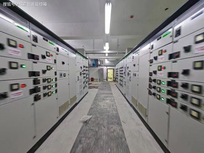
Integration with Digital Monitoring Systems
Modern transformers may include SCADA or IoT-based monitoring to enhance visibility and trend-based maintenance.
| Digital Feature | Description |
|---|---|
| Remote Thermal Monitoring | RTDs and fiber-optic sensors transmit real-time data |
| Online DGA Monitoring | Continuous tracking of fault gases |
| Alarm Logging Systems | Record historical trips, alarms, resets |
| Predictive Analytics | AI/ML tools forecast remaining life or risk |
These systems help shift from reactive to predictive maintenance, reducing emergency repairs and increasing uptime.
Online gas monitoring systems can help prevent unexpected transformer failures.True
Continuous DGA monitoring detects internal faults before they escalate, enabling preemptive maintenance and system protection.
Conclusion
Understanding whether a transformer is wet or dry is fundamental for proper operation, safety protocols, and environmental management. By examining external features, nameplate details, and the operating environment, users can easily distinguish between oil-filled and dry-type transformers. Correct identification also ensures that the right maintenance and protection measures are applied throughout the transformer's service life.
FAQ
Q1: What is a shell-type transformer?
A1: A shell-type transformer is a type of transformer where the magnetic core surrounds the windings, forming a shell-like structure. In this design:
The windings are placed on the central limb,
While the side limbs complete the magnetic circuit,
This configuration provides better protection, low leakage reactance, and superior short-circuit strength, making it ideal for high-voltage and industrial applications.
Q2: How is the core structure different from a core-type transformer?
A2: The main difference lies in the magnetic circuit design:
In a core-type transformer, the windings surround the core limbs.
In a shell-type transformer, the core surrounds the windings.
This results in:
Two magnetic paths in shell-type vs. one in core-type
Compact design and better mechanical support in shell-type
Higher efficiency under short-circuit conditions
Shell-type is often used where space, strength, and fault tolerance are priorities.
Q3: What are the advantages of shell-type transformers?
A3: Shell-type transformers offer:
Higher mechanical strength to withstand fault forces
Better short-circuit performance due to magnetic flux control
Reduced leakage reactance, enhancing voltage regulation
Compact and symmetrical design, which improves heat distribution
They are widely used in rectifier transformers, electric furnaces, and large industrial power supplies.
Q4: Are there any disadvantages to using shell-type transformers?
A4: Yes, shell-type transformers have some limitations:
Complex manufacturing and higher cost due to intricate core and winding layout
More insulation required between layered windings
Heavier and bulkier than core-type in some cases
They are not always ideal for standard distribution applications where cost and simplicity are more critical.
Q5: Where are shell-type transformers commonly used?
A5: You’ll often find shell-type transformers in:
High-power industrial applications (e.g., steel mills, smelters)
Traction systems (e.g., railway substations)
Converter and rectifier stations
High-voltage lab equipment
Their durability, energy efficiency, and short-circuit resistance make them ideal for mission-critical installations.
References
Electrical4U: Shell-Type Transformer Explained
https://www.electrical4u.com/shell-type-transformer/
IEEE C57.12.10: Standard for Power Transformers
https://standards.ieee.org/standard/C57_12_10-2017.html
Doble Engineering: Transformer Core Design and Testing
https://www.doble.com/solutions/core-analysis/
NPTEL: Transformer Core Design Video Lecture
https://nptel.ac.in/courses/108/105/108105053
ScienceDirect: Performance Analysis of Shell-Type Transformers
https://www.sciencedirect.com/science/article/pii/S187661021731018X
