A step-up transformer plays a vital role in power generation and transmission, particularly in boosting voltage levels to reduce energy losses over long distances. Found in power stations and renewable energy installations, these transformers increase the voltage while decreasing the current to ensure efficient high-voltage transmission. Understanding how step-up transformers function provides insight into their significance in modern electrical infrastructure.
What Is a Step-Up Transformer?

In power systems, transporting electricity efficiently over long distances requires boosting the voltage to reduce energy loss. That’s where step-up transformers come into play. Without them, the power generated at plants would suffer excessive transmission losses, making modern power grids infeasible. However, using them improperly can lead to overvoltages, insulation failure, and safety hazards—so understanding their function and design is essential for electrical engineers, utility operators, and system planners.
A step-up transformer is a type of power transformer that increases voltage from a lower input level (primary) to a higher output level (secondary), while proportionally decreasing current. It is used mainly at power generation stations to raise the voltage for efficient long-distance transmission. The step-up effect is achieved by having more turns in the secondary winding than in the primary winding.
This article offers a complete technical overview of step-up transformers—how they work, where they are used, and what considerations are critical to their design and operation.
Step-up transformers increase voltage and reduce current to minimize energy loss during long-distance power transmission.True
By stepping up voltage, these transformers reduce I²R losses in transmission lines, improving efficiency.
Step-up transformers reduce voltage at the substation to make it usable for homes.False
That function belongs to step-down transformers; step-up units are used near generation sources to raise voltage.
1. How a Step-Up Transformer Works
Fundamental Principle:
Electromagnetic induction via mutual flux linkage between primary and secondary coils.
| Component | Function |
|---|---|
| Primary winding | Receives low voltage (e.g., 11–25 kV) from generator |
| Secondary winding | Delivers high voltage (e.g., 132–400+ kV) to transmission lines |
| Core | Provides magnetic path for efficient flux linkage |
Voltage Ratio Equation:
$$\frac{V_2}{V_1} = \frac{N_2}{N_1}$$
Where:
- $V_1$ = primary voltage
- $V_2$ = secondary voltage
- $N_1$ and $N_2$ = number of turns in primary and secondary windings
In step-up transformers: $N_2 > N_1$ → $V_2 > V_1$
2. Typical Voltage Levels
| Stage | Voltage Range (kV) |
|---|---|
| Generator output | 11–25 kV |
| Step-up transformer output | 110–765 kV |
| Transmission line | 132–765 kV |
Common ratings: 11/132 kV, 13.8/230 kV, 20/400 kV
3. Applications of Step-Up Transformers
| Application Area | Purpose |
|---|---|
| Power plants | Raise voltage for grid connection |
| Wind farms | Boost low generator output to grid level |
| Solar PV stations | Convert inverter AC output for transmission |
| Industrial cogeneration | Export surplus energy to main grid |
Often found in Generator Step-Up (GSU) substations at the output of large turbines.
4. Advantages of Step-Up Transformers
| Benefit | Description |
|---|---|
| Reduced transmission loss | Lower current means less I²R heating loss |
| Improved efficiency | Voltage increase improves power transfer |
| Grid voltage compatibility | Matches generator to grid voltage levels |
| Supports renewable integration | Enables long-distance transport from remote locations |
Losses in a 100 km transmission line can drop over 90% when using high-voltage step-up systems.
5. Key Design and Safety Considerations
| Parameter | Design Strategy |
|---|---|
| Insulation strength | Must withstand high output voltages |
| Cooling system | Oil-cooled (ONAN/ONAF), forced air or water |
| BIL rating | High Basic Insulation Level for lightning |
| Vector group selection | Must match grid synchronization (e.g., YNd11) |
| Short-circuit withstand | Critical for fault resilience |
Typical Protection Devices:
- Surge arresters
- Buchholz relay
- Differential protection relays
- Pressure relief valves
6. Step-Up vs. Step-Down Transformers
| Feature | Step-Up Transformer | Step-Down Transformer |
|---|---|---|
| Voltage Output | Higher than input | Lower than input |
| Used at | Generator stations | Distribution substations |
| Turn ratio | N₂ > N₁ | N₂ < N₁ |
| Output current | Lower than input | Higher than input |
| Cooling system | Heavier duty (ONAF, OFWF) | May be lighter or dry-type |
7. Example: Generator Step-Up Transformer Specification
| Parameter | Example Specification |
|---|---|
| Rated Power | 250 MVA |
| Voltage (primary/secondary) | 13.8 / 230 kV |
| Cooling | ONAF |
| Vector group | YNd11 |
| Impedance | 12.5% |
| BIL (Basic Insulation Level) | 1050 kV impulse withstand |
Designed to run continuously at full power with high reliability for decades.
Summary Table: Step-Up Transformer Overview
| Aspect | Value / Consideration |
|---|---|
| Purpose | Boost voltage for transmission efficiency |
| Input Voltage Range | 11–25 kV (from generators) |
| Output Voltage Range | 110–765 kV (to grid) |
| Turn Ratio | N₂ > N₁ |
| Application Areas | Power stations, renewables, microgrids |
| Cooling Types | ONAN, ONAF, OFWF |
| Standards | IEC 60076, ANSI C57, IEEE C57.91 |
How Does a Step-Up Transformer Work?
Step-up transformers play a pivotal role in enabling high-voltage power transmission by converting low generator voltages into higher voltages suitable for grid delivery. Without step-up transformers, long-distance power transfer would face massive I²R losses, leading to inefficiency, overheating, and energy waste. Understanding their working mechanism is essential for designing reliable generation stations and compliant transmission networks.
A step-up transformer works on the principle of electromagnetic induction, where alternating current in the primary winding generates a changing magnetic field in the transformer's core. This flux induces a higher voltage in the secondary winding due to a greater number of coil turns, resulting in a voltage increase from primary to secondary while reducing current proportionally. The energy transfer remains constant (neglecting losses), preserving power conservation.
This article provides an in-depth technical explanation of how step-up transformers operate, using electromagnetic theory, design specifics, and real-world application contexts.
A step-up transformer increases voltage by using more turns in the secondary coil than in the primary, based on electromagnetic induction.True
The transformer law dictates that voltage is proportional to the ratio of coil turns; a higher secondary turn count produces a higher output voltage.
A step-up transformer increases voltage by adding electrical energy through external sources.False
Transformers do not generate energy; they only transform voltage and current using the same input power, minus losses.
1. Basic Working Principle: Faraday’s Law of Induction
Core Principle:
A changing magnetic field induces an electromotive force (EMF) in a coil.
$$\text{EMF} = -N \frac{d\Phi}{dt}$$
Where:
- $N$ = number of turns
- $\Phi$ = magnetic flux
Transformer Voltage Law:
$$\frac{V_2}{V_1} = \frac{N_2}{N_1}$$
- $V_1$ = voltage in primary coil
- $V_2$ = voltage in secondary coil
- $N_1$, $N_2$ = number of turns in each coil
In a step-up transformer:
$$N_2 > N_1 \Rightarrow V_2 > V_1$$
2. Component-Level Function
| Component | Role in Step-Up Function |
|---|---|
| Primary winding | Accepts input voltage from generator (low voltage) |
| Magnetic core | Channels the alternating magnetic flux |
| Secondary winding | More turns induce higher voltage (output) |
| Cooling system | Removes heat due to losses during operation |
The transformer does not change frequency or phase—only voltage and current levels.
3. Power and Current Relationships
Although voltage increases, power (P = VI) remains nearly constant (ignoring minor losses).
| Parameter | Relation |
|---|---|
| Power conservation | $V_1 I_1 \approx V_2 I_2$ |
| Current behavior | $I_2 < I_1$ |
| Result | High voltage, low current |
This low current output reduces resistive (I²R) losses in long-distance transmission.
4. Working Sequence in a Power Plant
- Generator produces 11–25 kV of AC voltage
- This voltage feeds the primary winding of the step-up transformer
- AC current creates a changing magnetic flux in the iron core
- Flux links with the secondary winding, which has more turns
- A higher voltage (e.g., 132 kV, 220 kV, 400 kV) is induced
- Output is sent to high-voltage transmission lines
5. Real-World Example
| Parameter | Value |
|---|---|
| Generator Output Voltage | 13.8 kV |
| Step-Up Transformer Ratio | 13.8 / 230 kV |
| Turn Ratio (N2\:N1) | 16.7 : 1 |
| Output Current Reduction | 16.7× less than input current |
| Loss Reduction | Transmission loss down by >90% |
6. Efficiency and Loss Considerations
| Loss Type | Description |
|---|---|
| Core (no-load) loss | Due to magnetization of core (constant) |
| Copper (load) loss | I²R losses in windings (load-dependent) |
| Stray losses | Induced currents in tank and clamps |
Efficiency of step-up transformers typically exceeds 98.5%, especially with ONAF or OFAF cooling systems.
7. Design Challenges in Step-Up Transformers
| Challenge | Engineering Solution |
|---|---|
| High insulation stress | Use high-grade oil and layered insulation |
| Lightning or switching surges | BIL-rated bushings, surge arresters |
| Core saturation at overvoltage | Controlled flux density, CRGO core design |
| Mechanical stress under fault | Reinforced winding clamping and spacers |
High-voltage design requires careful electromagnetic and thermal balancing.
Summary Table: Step-Up Transformer Operating Overview
| Attribute | Description |
|---|---|
| Operating Principle | Faraday’s law, mutual induction |
| Voltage Behavior | Increases from primary to secondary |
| Turn Ratio | $N_2 > N_1$ |
| Current Behavior | Decreases on secondary side |
| Energy Transfer | Constant power (minus losses) |
| Key Use | Generator to grid interface |
Where Are Step-Up Transformers Used?
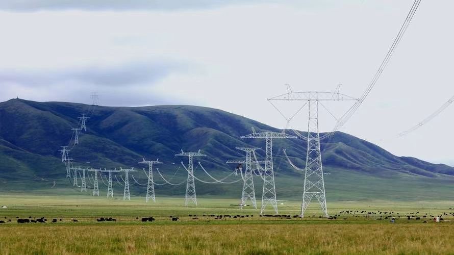
The modern power system relies heavily on efficient voltage transformation to deliver energy from generation sources to consumers. Step-up transformers are essential components at the front-end of this chain, increasing voltage to high levels that support long-distance transmission with minimal losses. Without them, electrical energy would dissipate as heat in the transmission lines, rendering nationwide or continental power grids impractical.
Step-up transformers are used wherever electrical energy needs to be transmitted over long distances from a generation site. Typical locations include thermal and hydroelectric power plants, wind farms, solar PV stations, industrial cogeneration facilities, grid-connected battery energy storage systems (BESS), and interconnection points between regional grids. In each case, they raise generator-level voltage (e.g., 11–25 kV) to transmission-grade levels (110–765 kV).
This article explores the various environments and scenarios where step-up transformers are deployed, illustrating their critical role in the energy value chain.
Step-up transformers are essential at power generation facilities to raise voltage levels for efficient transmission over long distances.True
They minimize current, reducing resistive losses and enabling cost-effective energy transport.
Step-up transformers are commonly used at residential and commercial buildings to provide usable voltage.False
Step-down transformers are used at the distribution level for end-use voltage; step-up units are used near generation sources.
1. Thermal Power Stations (Coal, Gas, Nuclear)
| Location | Role of Step-Up Transformer |
|---|---|
| Generator outlet (11–25 kV) | Transforms voltage up to 132–400 kV for transmission |
| GSU (Generator Step-Up) Unit | Connects turbine output to grid |
Largest GSUs are used at base-load fossil or nuclear plants, often rated >500 MVA.
2. Hydroelectric Power Plants
| Unique Characteristics | Step-Up Transformer Considerations |
|---|---|
| Often located in remote areas | Must raise voltage to reduce long-distance losses |
| Subject to high moisture/humidity | Transformers may require sealed or SF₆ insulation |
Typical voltage conversion: 13.8 kV → 230 kV
3. Wind Farms
| Application | Transformer Placement |
|---|---|
| Individual turbines | Step-up to 33 or 66 kV (pad-mounted) |
| Central substation | Step-up to 132/220/400 kV for grid tie-in |
| Wind Generation Voltage | Collector Grid Voltage | Transmission Voltage |
|---|---|---|
| 690 V – 1.2 kV | 33 or 66 kV | 110 – 400 kV |
Wind farms use multi-stage step-up transformer setups to aggregate power economically.
4. Solar Photovoltaic (PV) Power Plants
| Challenge | Solution Via Step-Up Transformer |
|---|---|
| PV inverter output is low-voltage (LV) | Stepped up to MV (33/66 kV), then HV (132/220 kV) |
| Variable output profile | Transformers must be rated for partial loading and fast switching events |
Utility-scale PV plants use dry-type or oil-immersed step-up units rated from 5–100 MVA.
5. Battery Energy Storage Systems (BESS)
| Application Area | Role of Step-Up Transformers |
|---|---|
| Grid-scale lithium-ion storage | Voltage step-up to MV/HV grid |
| Intermittent output | Must handle cycling, harmonics |
Often co-located with renewables or peaker plants to stabilize supply fluctuations.
6. Industrial Co-Generation (CHP) Facilities
| Industry | Voltage Output | Grid Interface via Step-Up Transformer |
|---|---|---|
| Cement, sugar, paper, steel | 6.6 / 11 / 13.8 kV | Step-up to 33 / 66 / 132 kV |
These transformers allow excess process power to be sold back to the utility.
7. Transmission Substations (Interconnection Nodes)
| Purpose | Step-Up Transformer Function |
|---|---|
| Tie regional grids | Match voltage levels for synchronized operation |
| Voltage bridging | e.g., 132 kV to 220 kV step-up |
Sometimes used in reverse mode as step-down, depending on energy flow.
8. Emergency Mobile Substations
| Feature | Use Case |
|---|---|
| Trailer-mounted step-up units | Temporary voltage boost during outages or construction |
| Flexible kVA ratings | Quick deployment in remote or disaster-affected areas |
Common in military, mining, and disaster response applications.
9. Case Study: Wind Farm Step-Up Design
| Parameter | Specification |
|---|---|
| Turbine output voltage | 0.69 kV |
| Collector transformer | 0.69 / 33 kV (dry-type) |
| Substation transformer | 33 / 132 kV (oil-immersed) |
| Output to transmission grid | 132 kV |
Enables seamless multi-MW wind integration to the regional grid.
Summary Table: Step-Up Transformer Usage Sites
| Use Case | Location/Stage | Voltage Change |
|---|---|---|
| Thermal power station | Generator output | 13.8 → 220/400/765 kV |
| Hydropower plant | Turbine terminal | 11/13.8 → 132/230/400 kV |
| Wind farm | Turbine → grid | 0.69 → 33 → 132/220 kV |
| Solar PV farm | Inverter → transmission | 0.4 → 33/66 → 132/220 kV |
| Battery storage plant | Inverter output | 0.6/0.8 → 33/66/132 kV |
| Industrial cogeneration | Process generator | 6.6/11 → 33/66/132 kV |
| Grid interconnect substation | Regional network tie-in | 110 → 220 or 132 → 400 kV |
What Are the Key Components of a Step-Up Transformer?
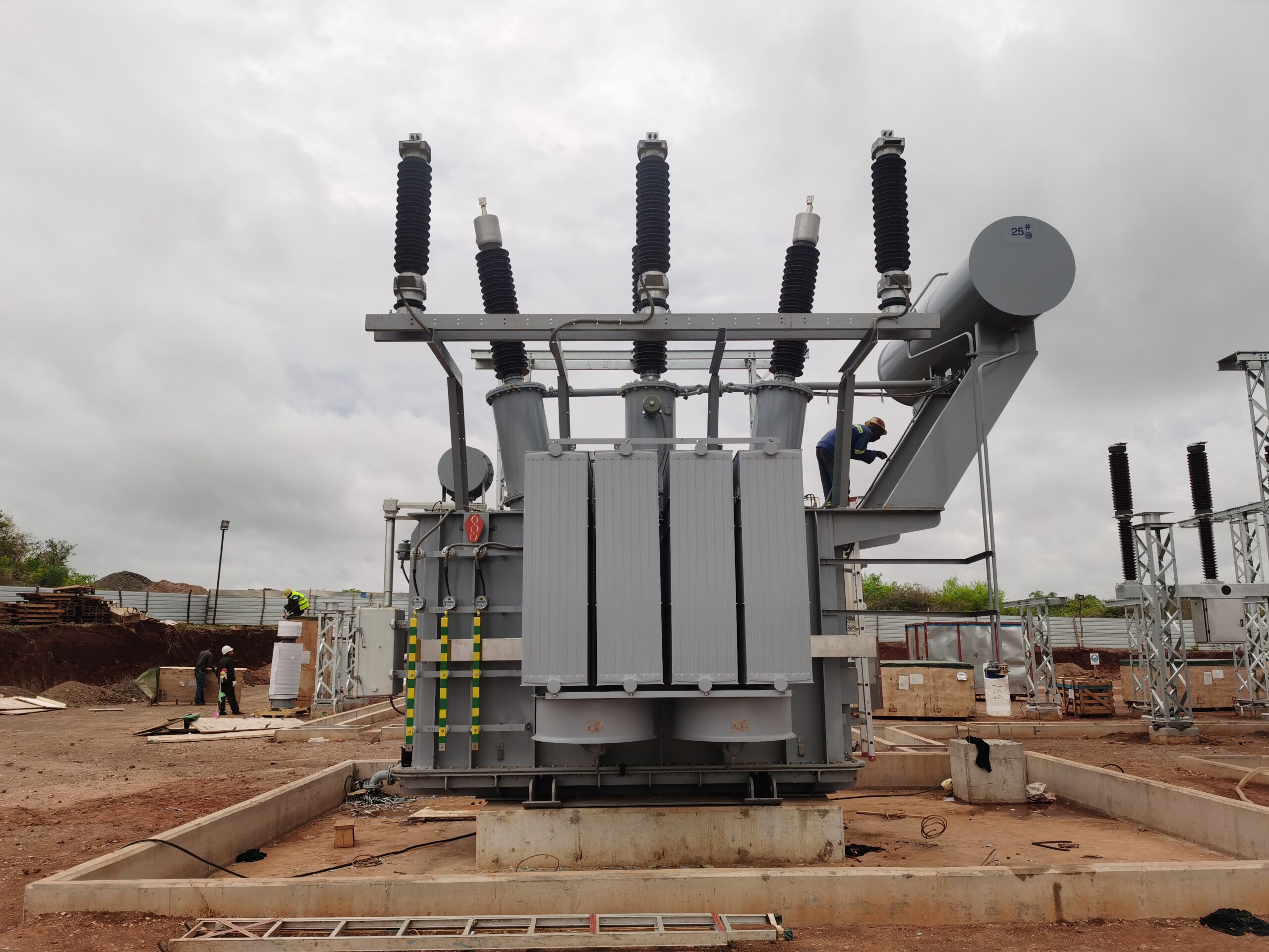
A step-up transformer is a complex and high-voltage electrical device that performs the vital function of increasing voltage for efficient transmission. While it may appear to be a simple tank externally, inside is a meticulously engineered system of electromagnetic and thermal components working together to ensure safe, stable, and efficient voltage transformation. Understanding these components is essential for design, maintenance, diagnostics, and custom transformer procurement.
The key components of a step-up transformer include the magnetic core, primary and secondary windings, insulation system, tank and enclosure, bushings, conservator tank, breather, radiator and cooling system, tap changer, and protection devices such as Buchholz relay and surge arresters. Each component plays a specific role in voltage transformation, thermal management, mechanical stability, and electrical safety.
This article breaks down the internal and external components of a step-up transformer and explains how they work together to deliver reliable high-voltage performance.
Step-up transformers consist of critical components such as the magnetic core, windings, bushings, and cooling system that together enable safe voltage elevation.True
These components are essential to handle electromagnetic conversion, insulation, heat dissipation, and structural integrity at high voltage levels.
A step-up transformer only includes two windings and operates without other support systems.False
High-voltage step-up transformers require additional components for cooling, insulation, voltage regulation, and safety.
1. Magnetic Core
| Component | Function |
|---|---|
| Laminated steel core (typically CRGO) | Channels the magnetic flux between windings |
| Core type | Core-type or shell-type |
| Material | Cold Rolled Grain-Oriented (CRGO) or Amorphous steel |
The core is the magnetic backbone of the transformer, designed to minimize hysteresis and eddy current losses.
2. Primary and Secondary Windings
| Winding Type | Description |
|---|---|
| Primary winding | Connected to generator (lower voltage) |
| Secondary winding | Connected to transmission line (higher voltage) |
| Conductor material | Copper or aluminum, with insulation |
| Arrangement | Cylindrical, helical, disc, or crossover coils |
In a step-up transformer, the secondary has more turns than the primary, increasing the output voltage.
3. Insulation System
| Component | Purpose |
|---|---|
| Solid insulation | Pressboard, kraft paper around windings |
| Liquid insulation | Transformer oil for dielectric strength and cooling |
| Insulation class | Defines temperature and dielectric limits (Class A, B, F, H) |
Proper insulation is crucial to prevent flashovers, arcing, and premature failure under high voltage stress.
4. Tank and Main Enclosure
| Feature | Role |
|---|---|
| Sealed steel tank | Contains core, windings, and insulating oil |
| Pressure relief device | Releases gas under fault condition |
| Expansion capacity | Accommodates thermal expansion of oil |
The tank provides mechanical protection, EMI shielding, and oil containment.
5. Cooling System
| Type | Description |
|---|---|
| ONAN (Oil Natural Air Natural) | Passive air cooling via radiators |
| ONAF (Oil Natural Air Forced) | Fans push air across radiators |
| OFWF (Oil Forced Water Forced) | For very large transformers (e.g., >400 MVA) |
| Cooling Components | Function |
|---|---|
| Radiators | Dissipate heat from oil |
| Cooling fans/blowers | Enhance air flow for rapid heat removal |
| Oil pumps (in forced systems) | Circulate oil for better heat exchange |
6. Conservator Tank and Breather
| Component | Function |
|---|---|
| Conservator tank | Accommodates oil expansion and contraction |
| Breather (with silica gel) | Filters moisture from incoming air |
These components maintain oil quality and prevent oxidation.
7. Bushings
| Feature | Purpose |
|---|---|
| HV and LV bushings | Enable external cable connection through tank |
| Material | Porcelain or composite polymer insulators |
| Rated for | High BIL (Basic Insulation Level) voltages |
Bushings are the electrical and mechanical interface to the outside world and must withstand both voltage and environmental exposure.
8. Tap Changer (OLTC or NLTC)
| Type | Function |
|---|---|
| Off-load tap changer (NLTC) | Manual voltage adjustment when de-energized |
| On-load tap changer (OLTC) | Automated voltage regulation during operation |
Tap changers allow the transformer to compensate for input voltage variations and maintain output stability.
9. Protection Devices and Monitoring Systems
| Device | Purpose |
|---|---|
| Buchholz relay | Detects gas from internal faults |
| Pressure relief valve | Vents oil vapor to prevent tank rupture |
| Oil level indicator | Monitors oil volume in conservator |
| Temperature sensors | Monitor hot-spot and top oil temperatures |
| Surge arresters | Protect against lightning and switching surges |
These systems help prevent catastrophic failures, enable predictive maintenance, and ensure safe operation.
Summary Table: Key Step-Up Transformer Components
| Component | Function |
|---|---|
| Core | Magnetic flux pathway |
| Windings | Voltage transformation via electromagnetic induction |
| Insulation system | Dielectric protection and thermal endurance |
| Tank | Enclosure and structural integrity |
| Cooling system | Heat dissipation to maintain operational temperature |
| Conservator & breather | Oil expansion control and moisture protection |
| Bushings | High-voltage interface with external connections |
| Tap changer | Voltage adjustment for stability |
| Protection devices | Safety monitoring and fault prevention |
Why Is Voltage Increased for Long-Distance Transmission?
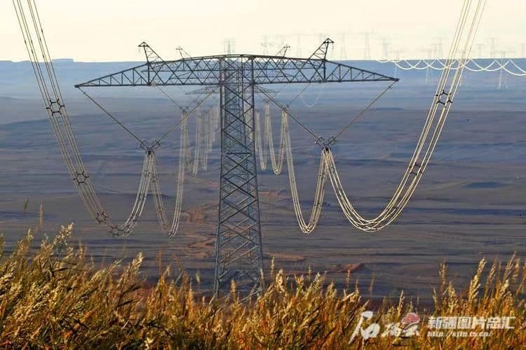
One of the most fundamental principles in power system design is that electricity must be transmitted at high voltage levels over long distances. Without this strategy, national or continental power grids would be grossly inefficient, uneconomical, and environmentally unsustainable. Yet many outside the electrical engineering community still wonder: why go to such lengths to increase voltage, only to decrease it again near the point of use?
Voltage is increased for long-distance transmission to significantly reduce energy losses caused by resistance in the conductors. According to Joule’s law (Power loss = I²R), transmitting power at higher voltages allows the current to be reduced, which in turn lowers resistive losses and allows thinner, more economical conductors. This approach maximizes transmission efficiency, reduces infrastructure costs, and improves power quality over vast distances.
This article offers a comprehensive explanation of the technical, economic, and physical reasons behind high-voltage transmission and the critical role of step-up transformers in the modern power grid.
Transmitting electricity at higher voltage reduces current and thus minimizes power losses in transmission lines.True
Joule losses (I²R) decrease as current decreases, and higher voltage allows more power to be delivered at lower current.
Electricity is transmitted at high voltage for safety reasons, not for efficiency.False
High voltage transmission is primarily for efficiency and economic reasons, not safety—it actually increases insulation and protection needs.
1. Fundamental Concept: Power Transmission Equation
$$P = V \times I$$
Where:
- $P$ = power (watts)
- $V$ = voltage (volts)
- $I$ = current (amperes)
To transmit a given power $P$, increasing voltage $V$ means you can reduce current $I$.
2. Joule’s Law and Transmission Losses
$$\text{Power Loss} = I^2 \times R$$
Where:
- $I$ = current in the conductor
- $R$ = resistance of the transmission line
| Scenario | Current (A) | Power Loss (W) in Same Line |
|---|---|---|
| 1000 kW at 10 kV | 100 A | 100² × R = 10,000 × R |
| 1000 kW at 100 kV | 10 A | 10² × R = 100 × R |
Result: Reducing current by 10× reduces power loss by 100×—a quadratic benefit.
3. Role of Step-Up Transformers in High-Voltage Transmission
| Component | Function |
|---|---|
| Step-up transformer | Increases generator voltage (e.g., 11 kV → 220 kV) |
| Transmission line | Carries high-voltage, low-current electricity |
| Step-down transformer | Reduces voltage for end-user safety (e.g., 220 kV → 400 V) |
These transformers enable efficient energy transfer across hundreds of kilometers.
4. Economic Advantages of High Voltage
| Factor | High Voltage Impact |
|---|---|
| Line size | Lower current → smaller conductor cross-section |
| Tower spacing | Less sag due to reduced current |
| Transformer efficiency | Higher voltage allows better core/winding performance |
| Long-term OPEX | Reduced I²R losses = lower energy cost |
Lower current also means reduced reactive power losses and less voltage drop.
5. Common Transmission Voltage Levels
| Voltage (kV) | Application Range |
|---|---|
| 110 – 220 kV | Regional or state transmission |
| 400 – 500 kV | National or long-distance corridors |
| 765 kV and above | Ultra-high-voltage (UHV) systems |
At 400 kV, losses are significantly lower over 500+ km lines compared to lower voltage lines.
6. Real-World Example: Comparing Transmission Efficiency
| Parameter | 132 kV Line | 400 kV Line |
|---|---|---|
| Distance | 200 km | 200 km |
| Power Transmitted | 500 MW | 500 MW |
| Current | \~2.2 kA | \~0.72 kA |
| Estimated Line Losses | \~18–22 MW | \~3–5 MW |
Savings of 15+ MW over the same route translate to hundreds of thousands of dollars per year.
7. Challenges of High Voltage (and Why It’s Still Worth It)
| Challenge | Mitigation |
|---|---|
| Higher insulation cost | Use of gas-insulated switchgear (GIS), composite bushings |
| Arc flash hazard | Rigid grounding, protection relays |
| Tower complexity | Optimized design for high clearances |
Even with these challenges, the benefits of lower transmission loss and capital efficiency outweigh the costs.
Summary Table: Why Voltage Is Increased for Transmission
| Benefit | Explanation |
|---|---|
| Lower resistive losses | Current is reduced, so I²R loss drops significantly |
| Reduced conductor size | Smaller wires can carry required power |
| Improved voltage regulation | Less voltage drop over distance |
| Enhanced transmission capacity | More power delivered over the same corridor |
| Grid stability and efficiency | Less reactive power, better power factor |
What Safety and Efficiency Considerations Apply?
![]()
Operating a transformer, particularly a high-voltage step-up transformer, involves complex electrical, thermal, and mechanical risks that must be mitigated through design and operational safeguards. Simultaneously, there is constant pressure to achieve the highest possible efficiency—especially in today’s energy-conscious, regulation-driven market. Safety failures can lead to equipment destruction, grid outages, or even human injury, while inefficiencies quietly accumulate into significant financial and environmental costs.
Safety and efficiency considerations for transformers include the use of overcurrent protection devices, pressure relief systems, temperature monitoring, insulation coordination, and fire safety measures. On the efficiency side, loss minimization through optimized core and winding design, proper cooling, voltage regulation, and harmonic mitigation is critical. Together, these ensure reliable, long-life, and cost-effective operation in compliance with global electrical safety standards.
This article offers a thorough breakdown of both safety protocols and efficiency practices that apply to step-up transformers and other high-voltage systems.
Step-up transformers must meet strict safety and efficiency requirements to prevent failures and reduce energy losses.True
High-voltage systems pose thermal, electrical, and mechanical risks that must be mitigated while maintaining high efficiency to lower operating costs.
Transformer efficiency is only related to its load level and does not require design optimizations or protection systems.False
Transformer efficiency is influenced by multiple design elements, including material choice, insulation, cooling, and harmonic management—not just load.
1. Key Safety Considerations in Transformer Design and Operation
A. Overcurrent and Short-Circuit Protection
| Device | Function |
|---|---|
| Differential relay | Detects internal faults between windings |
| Buchholz relay | Senses gas accumulation from insulation failure |
| Current transformers (CTs) | Feed protective relays with input current |
| Circuit breakers | Isolate the transformer during fault conditions |
Protects against thermal damage, fire, or explosion due to overloading or internal faults.
B. Thermal Protection and Temperature Monitoring
| Safety Element | Function |
|---|---|
| Oil temperature sensors | Monitor top oil temperature |
| Winding temperature indicators | Detect internal overheating |
| Cooling fans/pumps | Triggered by thermal relays |
Overheating is the #1 cause of insulation breakdown and transformer failure.
C. Pressure Relief Systems
| Component | Purpose |
|---|---|
| Pressure relief valve | Vents excess internal pressure from gas buildup |
| Gas-actuated relays | Trigger alarms or shutdown on abnormal pressure |
Prevents tank rupture during internal arcing or rapid oil vaporization.
D. Insulation and Dielectric Safety
| Design Parameter | Consideration |
|---|---|
| Basic Insulation Level (BIL) | Withstands lightning and switching surges |
| Creepage distance | Avoids surface tracking across bushings |
| Oil testing (DGA, BDV) | Maintains dielectric integrity |
Insulation failure causes catastrophic arcing—maintain through routine tests and oil purification.
E. Fire and Explosion Safety
| Prevention Mechanism | Purpose |
|---|---|
| Fire barriers or vaults | Contain fires and protect surrounding assets |
| Nitrogen blanketing | Prevents oil vapor ignition in sealed tanks |
| Dry-type transformers | Used indoors to reduce fire hazard |
Fire-rated transformers comply with NFPA, IEC 60076-14, and UL 1561.
2. Key Efficiency Considerations
A. Minimizing No-Load (Core) and Load (Copper) Losses
| Design Feature | Efficiency Impact |
|---|---|
| CRGO or amorphous metal cores | Reduces hysteresis and eddy current loss |
| Thicker copper windings | Lowers I²R losses at full load |
| Compact core stacking | Reduces stray flux and leakage reactance |
Optimized design reduces continuous operating loss, improving total lifecycle efficiency.
B. Optimal Cooling and Heat Dissipation
| Cooling Type | Efficiency Benefit |
|---|---|
| ONAN | Passive, low-maintenance |
| ONAF or OFWF | Allows higher ratings without overheating |
| Smart fan control | Activates only when needed, saving energy |
Maintaining safe temperature improves efficiency and lifespan.
C. Tap Changer and Voltage Regulation
| Device | Efficiency Advantage |
|---|---|
| On-load tap changer | Adjusts output to match voltage demand |
| Voltage regulator relay | Prevents overexcitation and core saturation |
Helps avoid overvoltage energy loss and keeps system within nominal operating range.
D. Harmonic Management
| Cause | Impact on Efficiency |
|---|---|
| Nonlinear loads (e.g., VFDs, data centers) | Increases eddy current losses and heating |
| K-rated transformer designs | Withstand harmonic loads without overheating |
Harmonic distortion raises losses and requires K-factor-rated or specially shielded windings.
E. Load Factor Optimization
| Load Condition | Typical Efficiency (%) |
|---|---|
| 25% load | 96–97% |
| 50% load | 97–98.2% |
| 75–100% load | 98.5–99.2% |
Operating transformers near their design load provides peak efficiency.
3. Maintenance Practices for Safety and Efficiency
| Practice | Safety Benefit | Efficiency Benefit |
|---|---|---|
| Routine oil testing | Detects insulation failure early | Maintains dielectric strength |
| Infrared thermography | Locates overheating spots | Identifies inefficiencies or faults |
| Cleaning bushings & radiators | Prevents tracking or overheating | Improves cooling and insulation |
| Load logging and harmonic analysis | Avoids overload damage | Optimizes energy flow |
Summary Table: Safety & Efficiency Essentials
| Category | Key Measures |
|---|---|
| Safety | Protection relays, insulation systems, thermal monitoring, surge arresters |
| Efficiency | Core/winding design, smart cooling, voltage regulation, harmonic filtering |
| Compliance | IEC, ANSI, IS, NFPA, ISO standards |
| Monitoring | Oil analysis, IR scanning, SCADA integration |
Conclusion
Step-up transformers are essential for transmitting electrical energy efficiently from generation sites to end users across long distances. By raising voltage levels, they minimize power losses and ensure the stability of the power grid. With widespread use in traditional and renewable energy systems alike, step-up transformers are fundamental to the reliable and efficient delivery of electricity in today’s energy landscape.
FAQ
Q1: What is a step-up transformer?
A1: A step-up transformer is an electrical device that increases the voltage from the primary side to the secondary side. It’s commonly used in power generation stations to raise voltage levels for efficient long-distance electricity transmission.
Q2: How does a step-up transformer work?
A2: A step-up transformer operates on the principle of electromagnetic induction. It has more turns in the secondary winding than in the primary winding. When alternating current flows through the primary coil, it generates a magnetic field in the core, which induces a higher voltage in the secondary coil.
Q3: Where are step-up transformers used?
A3: Step-up transformers are used in:
Power generation plants to transmit electricity over long distances
Renewable energy systems like solar and wind farms
Industrial facilities needing higher voltages for machinery
HVAC (High Voltage Alternating Current) transmission lines
Q4: What are the advantages of using a step-up transformer?
A4: Advantages include:
Reduced transmission losses by increasing voltage and decreasing current
Improved transmission efficiency over long distances
Protection of transmission lines by minimizing energy dissipation
Compact design for voltage amplification without moving parts
Q5: What is the difference between a step-up and step-down transformer?
A5: A step-up transformer increases voltage and decreases current, whereas a step-down transformer reduces voltage and increases current. They have opposite turn ratios and serve different purposes in the power grid: step-up for transmission and step-down for distribution.
References
"Step-Up Transformer Basics and Operation" – https://www.transformertech.com/step-up-transformer-guide – Transformer Tech
"Understanding Step-Up Transformers in Power Systems" – https://www.powermag.com/step-up-transformer-operation – Power Magazine
"How Step-Up Transformers Work" – https://www.electrical4u.com/step-up-transformer – Electrical4U
"Transformer Voltage Step-Up Theory and Applications" – https://www.sciencedirect.com/step-up-transformer-theory – ScienceDirect
"Step-Up Transformers for Renewable Energy Integration" – https://www.researchgate.net/step-up-transformers-renewable – ResearchGate
"Smart Grid Use of Step-Up Transformers" – https://www.smartgridnews.com/step-up-transformers-smart-grid – Smart Grid News
"Transmission Efficiency with Step-Up Transformers" – https://www.energycentral.com/c/ee/step-up-transformer-efficiency – Energy Central
"PowerGrid Guide to Step-Up vs. Step-Down Transformers" – https://www.powergrid.com/step-up-vs-step-down-transformers – PowerGrid