Transformers are critical components in electrical systems, designed for long-term, stable operation. However, they are not immune to failure. Understanding the most common cause of transformer damage is essential for effective maintenance, prevention strategies, and system reliability. This article explores the leading cause—and what can be done to minimize its impact.
What Is the Leading Cause of Transformer Failure?
Transformer failures can lead to widespread power outages, equipment damage, safety hazards, and high financial losses. While transformers are designed for long lifespans—typically 25–40 years—many fail prematurely due to internal degradation, environmental conditions, or poor maintenance. Understanding the single most common root cause of transformer failure is essential for utility engineers, facility managers, and maintenance planners looking to increase equipment reliability.
The leading cause of transformer failure is insulation degradation, primarily due to overheating and moisture ingress. Over time, thermal stress, oxidation, electrical overloading, and contamination break down the solid (paper) and liquid (oil) insulation systems inside the transformer. This reduces dielectric strength, leading to partial discharges, arcing, and eventual catastrophic breakdown.
Insulation deterioration is typically slow and undetected until it causes irreversible internal faults—making monitoring and preventive maintenance critical to long-term transformer health.
The primary cause of transformer failure is insulation degradation caused by overheating and moisture.True
As insulation weakens from thermal aging, electrical stress, and contaminants, the transformer becomes prone to internal faults and dielectric breakdown.
Transformer failure is mainly caused by external short circuits and lightning strikes.False
While external events contribute, the majority of failures stem from internal insulation deterioration over time.
1. Why Insulation Failure Is So Dangerous
| Insulation Function | Failure Risk When Degraded |
|---|---|
| Electrically isolates windings | May allow short circuits or arcing between phases |
| Withstands mechanical and thermal stress | Fails under inrush current or overload conditions |
| Works with oil to cool and insulate | Loses dielectric strength, leading to overheating |
Once insulation deteriorates, the transformer becomes a ticking time bomb—especially under load or fault stress.
2. How Insulation Degrades Over Time
| Cause of Degradation | Mechanism | Effect |
|---|---|---|
| Thermal aging | High winding temperatures break cellulose bonds | Paper becomes brittle, cracks easily |
| Moisture ingress | Water enters through seals, breathers, or environment | Reduces oil dielectric strength |
| Oxidation of oil | Exposure to oxygen produces acids and sludge | Corrodes windings, damages insulation |
| Overloads and transients | High current causes dielectric stress | Localized heating and partial discharge |
| Contaminants or particles | Dirt, metals, or dissolved gases disrupt field integrity | Increases fault initiation likelihood |
A 10°C rise in winding temperature cuts insulation life by half, based on IEEE and IEC studies.
3. Signs That Insulation Is Failing
| Symptom | Likely Insulation Issue |
|---|---|
| High moisture in oil | Paper insulation is absorbing water |
| Increased CO and CO₂ in DGA | Cellulose breakdown from aging insulation |
| Rising hotspot temperatures | Overload or thermal degradation |
| Elevated power factor (tan delta) | Decreased insulation quality |
| Partial discharge activity | Voids or weak zones in insulation system |
These indicators appear long before a visible failure and should trigger maintenance or testing.
4. Real-World Failure Example: Insulation Breakdown
- Transformer: 132/33 kV, 100 MVA
- Age: 21 years
- Symptoms: CO₂ increase in DGA, elevated hotspot temp, sludge in oil
- Event: Internal arc across degraded turn-to-turn insulation
- Result: Loud explosion, oil ejection, tank rupture
- Root Cause: Accelerated thermal aging + moisture accumulation in cellulose
- Corrective Action: Unit replaced; spare added to inventory; oil filtration frequency doubled
Failure occurred despite no previous external fault—purely due to insulation degradation over time.
5. Secondary Causes That Accelerate Insulation Failure
| Factor | How It Contributes |
|---|---|
| Infrequent oil testing | Allows unnoticed moisture and acid buildup |
| Overloading transformer | Exceeds thermal limits, breaks insulation bonds |
| Poor ventilation | Raises internal temps, reduces cooling effectiveness |
| Inadequate maintenance | Delays detection of oil or insulation issues |
| Aging without rejuvenation | Insulation loses strength naturally over decades |
Insulation failure is often a combination of aging and neglect—not just age alone.
6. How to Prevent Insulation-Related Transformer Failures
| Preventive Measure | Benefit |
|---|---|
| Regular DGA and oil analysis | Detects gas buildup, moisture, oxidation early |
| IR thermography and load profiling | Tracks thermal hotspots and overload trends |
| Online moisture sensors | Monitors water ingress in real time |
| Scheduled oil filtration | Removes sludge, acids, and water |
| Insulation rejuvenation (depolarization) | Extends paper life and dielectric strength |
These actions can extend transformer life by 5–15 years, depending on condition and environment.
Summary Table: Why Insulation Failure Is the Leading Cause of Transformer Breakdown
| Cause | Failure Mechanism | Preventable? |
|---|---|---|
| Overheating | Breaks down insulation molecular bonds | ✅ With cooling/load control |
| Moisture ingress | Lowers dielectric strength of oil/paper | ✅ With sealed breathers, filtration |
| Oxidation and acid buildup | Corrodes insulation and windings | ✅ With oil testing and replacement |
| Paper aging | Brittle, cracks under electrical stress | ✅ With life management programs |
| Ignored warning signs | Small issues snowball into full failure | ✅ With proactive diagnostics |
How Does Insulation Degradation Lead to Damage in Transformers?
Transformer insulation isn’t just a passive material—it is the frontline defense against electrical breakdown, overheating, and catastrophic failure. The insulation system, composed of oil and solid materials like cellulose paper, ensures that high voltages remain safely separated inside the transformer. But over time, this insulation degrades, and if left unchecked, it becomes the root cause of many irreversible faults. Insulation degradation sets off a dangerous chain reaction that leads to mechanical, thermal, and electrical destruction within the transformer.
Insulation degradation leads to damage in transformers by reducing the dielectric strength of the oil and paper, allowing electrical stress to cause partial discharges, localized heating, and eventually full electrical breakdown. This results in arcing between windings or from windings to the core, causing thermal burns, carbonization, insulation collapse, and even explosions in severe cases. Overheating, moisture, and oxidation are the primary contributors to this deterioration process.
The decline is gradual but dangerous—and once degradation passes a critical threshold, failure becomes inevitable and irreversible.
Insulation degradation can result in arcing, partial discharges, and catastrophic breakdowns within a transformer.True
As insulation weakens, dielectric strength drops, allowing electrical stress to initiate internal discharges that destroy the windings and insulation system.
Insulation has no impact on transformer reliability unless exposed to lightning or faults.False
Most transformer failures result from internal insulation aging—not external events.
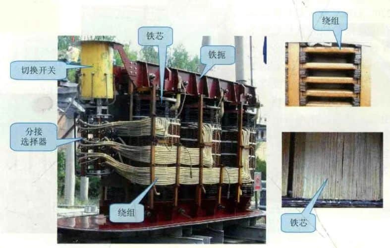
1. How the Insulation System Works (When Healthy)
| Component | Function |
|---|---|
| Cellulose paper | Electrically isolates adjacent windings and layers |
| Mineral or ester oil | Insulates and cools the windings and core |
| Pressboard spacers | Maintain gap distances and prevent winding movement |
| Oil tank and seals | Protect against moisture and oxidation |
A healthy insulation system ensures the transformer can withstand rated and transient voltages without arcing or overheating.
2. How Insulation Degrades Over Time
| Degradation Mechanism | Resulting Damage |
|---|---|
| Thermal aging (heat) | Breaks polymer chains in paper → loss of mechanical strength |
| Moisture ingress | Water reduces dielectric strength → flashover risk |
| Oxidation of oil | Produces acids → sludge formation → cooling loss |
| Electrical stress (PD) | Causes micro-arcs → carbon tracks in insulation |
| Contamination | Dust, metals, or gases disrupt voltage gradients |
The dielectric strength of insulation oil can drop from 40 kV to below 15 kV, making the system unsafe.
3. Step-by-Step Progression: From Degradation to Destruction
| Stage | What Happens |
|---|---|
| 1. Insulation absorbs moisture | Paper and oil attract humidity from air or leaks |
| 2. Dielectric strength declines | Electrical fields begin to stress weak spots |
| 3. Partial discharges begin | Tiny sparks damage insulation locally → CO₂ and C₂H₂ gases form |
| 4. Localized heating | Thermal spots exceed design limits → paper becomes brittle |
| 5. Arc develops through insulation | Winding short-circuits internally or to tank |
| 6. Internal pressure rise | Oil vaporizes, expands, and may ignite |
| 7. Explosion or tank rupture | Transformer violently fails—total loss |
Each stage increases failure probability exponentially, not linearly.
4. Diagnostic Indicators of Degrading Insulation
| Monitoring Parameter | Degradation Sign |
|---|---|
| Dissolved Gas Analysis (DGA) | Acetylene (C₂H₂) and CO/CO₂ indicate arcing/paper decay |
| Oil moisture ppm | Above 20 ppm = increased flashover risk |
| Insulation resistance (IR) | Declining IR indicates water or carbon tracking |
| Power factor / tan delta | Increase suggests weakening dielectric material |
| Hot spot temperature | Sustained high values = thermal aging zone |
Diagnostics help predict and prevent failure before irreversible damage occurs.
5. Real-World Example: Insulation Breakdown Case
- Transformer: 66/11 kV, 10 MVA
- Age: 16 years
- Issue: No previous external faults, but oil turned dark and gassy
- DGA results: High CO₂ and C₂H₂
- Action: Disassembled during scheduled outage
- Findings: Severe paper embrittlement, arcing between layers
- Outcome: Full rewind required + oil flush and vacuum drying
Root cause was years of moisture ingress + lack of filtration, not a sudden fault.
6. Consequences of Ignoring Insulation Degradation
| Failure Outcome | Impact |
|---|---|
| Internal flashover | Causes power outage and transformer loss |
| Fire or explosion | Threatens nearby equipment and personnel |
| Unplanned shutdown | Affects critical services like hospitals or factories |
| Environmental damage | Oil leaks contaminate soil and groundwater |
| High replacement cost | Often exceeds \$100,000–\$2 million per unit |
Over 50% of transformer failures are traced to undetected or ignored insulation deterioration.
7. How to Prevent Insulation-Driven Damage
| Preventive Measure | Effectiveness |
|---|---|
| Regular DGA (every 6–12 months) | Detects early-stage arcing or paper aging |
| Oil filtration and dehydration | Removes water, acids, and preserves dielectric strength |
| Thermal monitoring (hotspot sensors) | Alerts to overheating zones in real time |
| Online moisture sensors | Warns when humidity rises inside tank |
| Scheduled insulation testing (IR, PF) | Confirms long-term health of insulation system |
Preventive actions can extend transformer life by 5–15 years and avoid emergency failures.
Summary Table: How Insulation Degradation Leads to Transformer Damage
| Degradation Factor | Failure Mechanism | Final Result |
|---|---|---|
| Overheating | Paper burns, oil breaks down | Local arc or turn-to-turn short |
| Moisture | Reduces dielectric strength | Flashover, bushing failure |
| Oxidation | Produces sludge and acids | Core/winding overheating |
| Electrical partial discharges | Erodes insulation surfaces | Gas buildup, carbon tracking |
| Cumulative aging | Weakens mechanical support | Winding collapse or tank rupture |
What Role Do Overloads and Voltage Surges Play in Transformer Failure?
While transformer insulation degradation is the leading long-term cause of failure, overloads and voltage surges are among the most immediate, damaging, and dramatic contributors to transformer breakdowns. These electrical stresses can either trigger sudden catastrophic failure or accelerate the internal deterioration process significantly—especially when insulation is already weakened.
Overloads and voltage surges damage transformers by causing excessive heating, dielectric breakdown, and mechanical stress inside the windings and core. Overloads lead to sustained overheating that accelerates insulation aging and oil degradation. Voltage surges—often caused by lightning, switching operations, or faults—can exceed the dielectric strength of insulation and cause flashovers, arcing, or bushing explosions. Both stresses reduce transformer lifespan and can cause sudden failure if protective devices are insufficient or delayed.
Transformers are robust, but only within their rated thermal and electrical limits. Exceeding these limits—even briefly—can be fatal.
Overloads and voltage surges can directly cause transformer failure or accelerate insulation degradation leading to breakdown.True
Thermal stress from overloads and dielectric stress from surges degrade internal components and cause arcing, overheating, or physical deformation.
Transformers are immune to damage from overloads or short-term voltage spikes.False
Even short surges or prolonged overloads can severely damage windings, insulation, and bushings if not properly managed.
1. What Is an Overload in Transformer Terms?
| Condition | Definition |
|---|---|
| Normal Load | Operating within rated MVA/kVA and temperature rise |
| Overload | Current exceeds rated capacity for an extended period |
| Emergency Overload | Temporarily permitted by standards (e.g. 120–140% rated load) |
| Chronic Overload | Continuous overloading beyond design tolerance |
Overloading causes hotspot temperatures to exceed 110–140°C, leading to rapid aging of paper and oil insulation.
2. How Overloads Damage Transformers
| Overload Effect | Resulting Damage |
|---|---|
| Thermal stress on windings | Degrades paper insulation → brittleness and cracking |
| Hot oil zones | Triggers oxidation → sludge buildup and reduced cooling |
| Uneven temperature gradients | Causes mechanical deformation in winding structures |
| Prolonged core heating | Affects magnetic performance and accelerates core loss |
A 10°C increase in operating temperature halves the insulation life (Arrhenius law).
3. What Is a Voltage Surge or Transient?
| Source of Surge | Voltage Level | Duration |
|---|---|---|
| Lightning strike | Up to 1 MV or more | Microseconds to milliseconds |
| Switching surge | 1.5–3 p.u. (per unit) of system voltage | Microseconds to milliseconds |
| Capacitor bank energizing | 1.3–2.0 p.u. | Short-term |
| Grid fault backfeed or islanding | 1.1–1.8 p.u. | Depends on protection latency |
Surges are high-energy, short-duration spikes that challenge insulation and protection systems instantly.
4. How Voltage Surges Cause Transformer Damage
| Mechanism | Damage Caused |
|---|---|
| Insulation puncture | Flashover between turns or to tank |
| Bushing failure | External arc flash, ceramic explosion |
| Winding displacement | High electromagnetic forces deform or collapse windings |
| Partial discharges | Starts carbon tracking and weakens dielectric layers |
Surge arresters and bushings can absorb only a portion of the spike—extreme or repeated surges breach protection.
5. Real-World Examples: Overload and Surge Failures
Case A – Overload-Induced Breakdown
- Transformer: 11/0.4 kV, 250 kVA distribution
- Load condition: Operated at 145% of nameplate for 12 hours daily
- Failure: Core overheating led to internal insulation melting
- Result: Total burnout, required replacement
- Lesson: Overload history ignored, no thermal alarms in system
Case B – Surge-Induced Flashover
- Transformer: 132/33 kV, 63 MVA substation
- Event: Lightning surge bypassed degraded arrester
- Failure: Bushing exploded, internal arc caused oil fire
- Result: 10-day outage, environmental spill incident
- Lesson: Old arrester + aging insulation made system surge-sensitive
6. Preventive Measures Against Overloads and Surges
| Strategy | Protection Benefit |
|---|---|
| Overload monitoring (hot spot RTDs) | Tracks real-time thermal stress |
| Load shedding schemes | Prevents chronic overloads |
| Surge arresters (metal oxide type) | Diverts transient voltages to ground |
| Bushing maintenance and testing | Ensures insulation capacity under stress |
| Transformer differential protection | Detects internal faults from surge-related arcing |
IEEE and IEC standards define load curves and withstand capabilities—violating them shortens life.
Summary Table: How Overloads and Voltage Surges Damage Transformers
| Factor | Mechanism | Final Result |
|---|---|---|
| Thermal Overload | Insulation aging, winding deformation | Premature failure, reduced lifespan |
| Lightning Surge | Instant dielectric breakdown | Bushing blowout, arc flash, tank rupture |
| Switching Transient | Stress on weak spots in insulation | Turn-to-turn short, partial discharge buildup |
| Chronic Overcurrent | Continuous heating | Oil oxidation, sludge, hotspot degradation |
Can Moisture and Contamination Damage Transformers?
Transformers are designed to last decades, but their performance and longevity depend heavily on the integrity of their insulation system. One of the most dangerous, yet often underestimated, threats to that system is moisture and contamination. These elements silently weaken the dielectric strength of transformer oil and insulation paper, leaving the transformer vulnerable to internal failure, short circuits, and thermal breakdown. Even trace amounts of moisture can compromise performance.
Yes, moisture and contamination can significantly damage transformers. Moisture reduces the dielectric strength of insulation and oil, leading to partial discharges, flashovers, and accelerated aging. Contamination—such as metallic particles, sludge, acids, or fibers—can cause local hot spots, chemical degradation, or arcing within the winding structure. Together, they compromise both the thermal and electrical reliability of a transformer.
These threats are cumulative, often going unnoticed until they result in catastrophic failure.
Moisture and contamination can severely degrade transformer insulation, leading to arcing, overheating, and failure.True
Even small amounts of water or impurities reduce dielectric strength and initiate localized discharges and chemical breakdowns.
Moisture and contamination are harmless if the transformer oil is changed periodically.False
Changing oil alone is not sufficient—moisture and particles also accumulate in insulation and components, requiring filtration and diagnostics.
1. How Moisture Enters a Transformer
| Source of Moisture | How It Penetrates the Transformer |
|---|---|
| Ambient humidity | Breathers absorb moisture from air over time |
| Breather system failure | Silica gel saturation allows free water vapor intrusion |
| Leaky gaskets or seals | Rainwater or condensation seeps through enclosure points |
| Oil oxidation | Chemical breakdown produces water as a byproduct |
| Poor storage or transportation | Condensation forms on cold surfaces, absorbed by paper |
Cellulose insulation is hygroscopic—it absorbs moisture from the environment and retains it deep inside the structure.
2. How Moisture Damages Transformer Components
| Component Affected | Moisture-Related Impact |
|---|---|
| Cellulose paper insulation | Reduced dielectric strength, brittleness, breakdown |
| Insulating oil | Lower BDV (Breakdown Voltage), gas bubble formation |
| Core and windings | Corrosion, reduced mechanical strength |
| Tank and hardware | Rusting, sludge adhesion |
Moisture reduces oil dielectric strength from 40 kV to below 10 kV, increasing risk of flashover.
3. What Is Contamination in a Transformer?
| Type of Contaminant | Source |
|---|---|
| Metal particles | Arcing, abrasion, aging connections |
| Fibers or dirt | Manufacturing residue, maintenance debris |
| Oxidation by-products (sludge) | Oil aging, acid formation |
| Gases (CO, C₂H₂, CH₄) | Result of electrical discharges or thermal degradation |
Contaminants accumulate in oil and insulation, creating conductive paths and disrupting field uniformity.
4. Failure Mechanisms Caused by Moisture and Contamination
| Process | Effect on Transformer |
|---|---|
| Partial discharges | Starts at low dielectric points → leads to carbon tracking |
| Bubble formation | Causes electrical flashover in low-pressure zones |
| Sludge clogging | Blocks cooling ducts → overheating and oil breakdown |
| Chemical corrosion | Deteriorates core laminations, windings, and metal parts |
| Arcing between layers | Triggers short circuits, voltage collapse |
These mechanisms often occur deep inside the core, where visual inspection cannot detect them.
5. Diagnostic Tests for Moisture and Contamination
| Test | What It Detects |
|---|---|
| Dissolved Gas Analysis (DGA) | Moisture-driven gas evolution (CO, CO₂, C₂H₂, H₂) |
| Moisture in oil (ppm) | Confirms water content above safe thresholds (≤10 ppm ideal) |
| Power factor / tan delta | Measures insulation loss due to contamination |
| Furan analysis | Indicates cellulose paper breakdown |
| Oil dielectric strength (BDV) | Measures breakdown voltage drop due to contamination |
Regular oil testing is critical for early detection of moisture and contamination.
6. Real-World Example: Moisture-Induced Transformer Failure
- Transformer: 33/11 kV, 16 MVA substation
- Age: 12 years
- Symptoms: Elevated CO/CO₂ in DGA, rising tan delta, darkened oil
- Cause: Saturated breather + failed tank gasket
- Result: Moisture infiltrated cellulose, leading to internal flashover
- Damage: Partial winding collapse, unit decommissioned
- Remedy: New transformer + improved breather and oil filtration system
Moisture went undetected for over a year, despite regular oil changes.
7. Prevention and Mitigation Strategies
| Action | Benefit |
|---|---|
| Use of sealed or hermetic transformers | Prevents moisture ingress entirely |
| Install online moisture sensors | Real-time warning of water buildup |
| Oil filtration and dehydration | Removes water, sludge, and particulate contamination |
| Silica gel breather replacement | Keeps air entering tank moisture-free |
| Thermal vacuum drying of insulation | Removes deep-seated water in cellulose |
| Routine testing (DGA, BDV, PF) | Detects early-stage degradation |
A proactive moisture management program can extend transformer life by up to 40%.
Summary Table: Impact of Moisture and Contamination in Transformers
| Hazard | Cause | Damage Result |
|---|---|---|
| Moisture in oil/paper | Leaks, humidity, breather failure | Flashover, dielectric failure |
| Contaminants (sludge, particles) | Oil aging, wear debris | Arcing, blockage, insulation loss |
| Bubble formation | Overload + moisture | Instant dielectric breakdown |
| Acid and oxidation | Oil degradation | Corrosion of windings and metal parts |
How Does Lack of Maintenance Contribute to Transformer Failure?
Transformers are engineered for durability and long life—but that doesn’t mean they’re immune to aging, environmental stress, or internal faults. In fact, one of the most preventable causes of transformer failure is the lack of regular maintenance. Skipping inspections, ignoring test schedules, or failing to service components doesn’t just increase the risk of breakdown—it virtually guarantees it. Maintenance isn’t just about compliance; it’s the front line of transformer longevity, reliability, and safety.
Lack of maintenance contributes to transformer failure by allowing moisture buildup, insulation degradation, oil contamination, thermal imbalance, and undetected mechanical faults to worsen over time. Without routine diagnostics and servicing, emerging issues—such as sludge formation, corroded terminals, bushing cracks, or oil degradation—go unnoticed, leading to partial discharges, overheating, or sudden catastrophic failure.
Poor maintenance turns manageable wear into expensive, unplanned outages.
Neglecting transformer maintenance can lead to insulation failure, overheating, and ultimately equipment breakdown.True
Unmonitored transformers accumulate moisture, contamination, and internal defects that escalate into failures without preventive action.
Transformers are maintenance-free and rarely require inspection.False
Transformers need scheduled diagnostics and component servicing to prevent failure from aging, contamination, and environmental exposure.
1. Key Maintenance Tasks and What Happens If You Skip Them
| Maintenance Task | Purpose | If Ignored |
|---|---|---|
| Oil testing and filtration | Detects moisture, sludge, and acidity in dielectric fluid | Oil degrades → flashover risk increases |
| Dissolved Gas Analysis (DGA) | Identifies incipient faults via gas patterns | Internal discharges go undetected → arcing |
| Bushing inspection and cleaning | Prevents tracking and external flashovers | Pollution buildup → bushing rupture |
| Cooling system maintenance | Ensures radiators and fans operate properly | Overheating → insulation aging, hotspot faults |
| Thermal imaging (IR scan) | Detects hotspot formation and load imbalance | Unbalanced phases → winding or terminal burn |
| Grounding and connection checks | Secures safety and operational integrity | Loose terminals → arcing, partial discharge |
These are simple preventive measures—yet failure to perform them leads to complex breakdowns.
2. Consequences of Poor Maintenance Over Time
| Neglect Area | Failure Result |
|---|---|
| Dirty or degraded oil | Dielectric strength falls → insulation breakdown |
| Untested bushings | External tracking → catastrophic rupture |
| Unmaintained fans or radiators | Hotspot temperatures climb → insulation life drops |
| Ignored DGA alerts | Arcing continues → leads to full short circuit |
| Missed mechanical inspections | Loose parts vibrate → structural failure or short |
Maintenance is like healthcare for your transformer—skipping it leads to cumulative decay.
3. Real-World Failure Caused by Maintenance Neglect
- Unit: 132/33 kV, 63 MVA power transformer
- Age: 19 years
- Maintenance record: No oil filtration in 6 years; DGA overdue by 18 months
- Failure: Sudden explosion during load surge
- Investigation findings: Moisture levels at 45 ppm, sludge in radiator coils, C₂H₂ level spiked but unmonitored
- Outcome: Transformer declared irreparable, cost > \$900,000, 3-week outage
This failure was 100% preventable with routine maintenance and DGA alerts.
4. Warning Signs Often Missed Due to Poor Maintenance
| Warning Sign | What It Means |
|---|---|
| Darkened oil or sludge in sight glass | Oil oxidation and internal contamination |
| Rising CO/CO₂ in DGA report | Cellulose insulation breakdown in progress |
| Humming noise or vibration changes | Winding loosening or magnetostriction issue |
| Oil leak stains around tank seals | Gasket aging → moisture ingress risk |
| Higher than usual thermal hotspot | Overload or cooling failure |
These signs can be detected months before failure—if maintenance is done.
5. Why Utilities and Facilities Skip Maintenance (and Why That’s Risky)
| Excuse | Reality Check |
|---|---|
| “It’s still running fine.” | Faults grow invisibly until catastrophic |
| “We don’t have time or budget.” | Emergency repairs cost 3–10× more than maintenance |
| “It’s low-voltage, not critical.” | Even small failures can trigger system-wide damage |
| “OEM says it’s sealed.” | Even sealed units require inspection of bushings, connections, and oil quality |
The cost of maintenance is small compared to the cost of failure.
6. Best Practices for a Preventive Maintenance Program
| Maintenance Activity | Frequency |
|---|---|
| Oil BDV and moisture test | Every 6–12 months |
| DGA analysis | Every 6–12 months or after any disturbance |
| Bushing inspection | Annually or after storms/pollution |
| Cooling system service | Annually |
| IR thermography scan | Quarterly or semi-annually |
| Physical inspection (leaks, seals) | Quarterly |
| Tan delta / power factor testing | Every 3–5 years or after 10 years in service |
A structured plan using IEC and IEEE guidelines will extend life and reduce outages.
Summary Table: How Lack of Maintenance Leads to Transformer Failure
| Neglected Task | Ignored Effect | Failure Mode |
|---|---|---|
| Oil testing/filtration | Contamination and low BDV | Dielectric breakdown → flashover |
| DGA analysis | Undetected arcing or overheating | Turn-to-turn short → catastrophic failure |
| Bushing inspection | Surface tracking or cracks | External arc → explosion or trip |
| Radiator/fan maintenance | Cooling loss → insulation aging | Hotspot failure, fire risk |
| Terminal torque checks | Loose connections | Arcing, heating, connection burnout |
What Preventive Measures Help Avoid Common Transformer Damage?

Transformers are at the heart of every power system, yet they face constant threats from overheating, insulation degradation, moisture, overloading, and electrical surges. While transformer failures can be costly and catastrophic, the good news is that most damage is preventable through a combination of proactive maintenance, real-time monitoring, and protective hardware. Implementing a sound preventive strategy helps ensure system reliability, asset longevity, and operational safety.
The most effective preventive measures to avoid common transformer damage include routine oil analysis (especially DGA and moisture tests), proper load management to avoid overloading, surge protection systems, thermal and IR monitoring, regular physical inspections, and maintaining clean, dry insulation systems. These strategies detect early warning signs and mitigate risks before damage becomes irreversible.
Transformers don’t fail without warning—they reveal problems in advance, and prevention is about listening.
Preventive measures like oil testing, surge protection, and thermal monitoring can reduce transformer failure rates significantly.True
These measures detect degradation early, allowing corrective action before a fault escalates into failure.
Transformer damage is mostly unpredictable and cannot be prevented.False
Over 70% of transformer failures are caused by preventable conditions like moisture, overheating, and insulation breakdown.
1. Routine Testing and Monitoring
| Test / Monitoring Tool | Purpose | Frequency |
|---|---|---|
| Dissolved Gas Analysis (DGA) | Detects arcing, overheating, insulation breakdown | Every 6–12 months |
| Moisture in oil (ppm) | Reveals risk of flashover and aging | Quarterly or during DGA |
| Oil BDV (Breakdown Voltage) | Measures dielectric strength of oil | Annually or after filtration |
| Infrared Thermography | Detects hotspots, imbalanced loads | Quarterly or seasonal |
| Tan Delta / Power Factor | Indicates insulation condition | Every 3–5 years |
Consistent testing helps identify failure trends before they escalate, especially in aging or high-duty transformers.
2. Surge Protection and Grounding Systems
| Protective Device | Function |
|---|---|
| Surge arresters (MOV type) | Diverts lightning and switching surges to ground |
| Bushing capacitance monitors | Detect degradation of insulation under surge stress |
| Neutral grounding resistors (NGRs) | Limits fault current during ground faults |
| Static discharge devices | Prevent buildup of electrostatic potential |
Surges can occur without visible lightning—internal switching is equally dangerous. Arresters must be tested regularly.
3. Load and Thermal Management
| Measure | Purpose |
|---|---|
| Real-time load monitoring | Avoids thermal overload and load imbalance |
| Hotspot temperature sensors (RTDs) | Alerts to insulation risk zones |
| Cooling system maintenance | Ensures radiators and fans operate at full efficiency |
| On-Load Tap Changer (OLTC) checks | Prevents contact wear and voltage mismatch |
Excess heat is the #1 enemy of transformer longevity—monitoring and ventilation are critical.
4. Oil Management and Filtration
| Oil Service Task | Preventive Benefit |
|---|---|
| Periodic oil filtration | Removes acids, water, and sludge |
| Vacuum dehydration | Dries out both oil and cellulose insulation |
| Dielectric oil replacement | Restores insulation strength after aging |
| Online filtration systems | Continuous moisture and particle removal |
Dirty oil = weak insulation. Clean oil protects both thermal and electrical integrity.
5. Physical Inspection and Preventive Maintenance
| Inspection Area | What to Check |
|---|---|
| Bushing surfaces | Cleanliness, cracks, corona marks |
| Tank seals and gaskets | Signs of leaks, bulging, or corrosion |
| Conservator and breather | Silica gel color (moisture) and oil level |
| Radiators and fans | Dust blockage, fan operation status |
| Grounding and cable terminations | Tightness, discoloration, or vibration |
These simple visual checks prevent dangerous faults caused by loose parts, leaks, or environmental exposure.
6. Protection Relay Coordination and SCADA Integration
| Digital Protection | Role in Prevention |
|---|---|
| Differential protection | Detects internal faults instantly |
| Overcurrent relays | Prevents thermal overload damage |
| Buchholz relay testing | Triggers trip on gas accumulation or oil surge |
| SCADA integration | Enables real-time alarms, historical data, and trend analysis |
Advanced relays and SCADA systems provide early alerts and reduce restoration time.
7. Environmental Controls and Enclosure Integrity
| Protective Measure | Why It Matters |
|---|---|
| Weatherproof enclosures | Protects against rain, dust, rodents |
| Anti-condensation heaters | Prevents internal humidity and water collection |
| Bird guards and bush barriers | Prevent wildlife-induced flashovers |
| UV and pollution shields | Prevents bushing surface breakdown in polluted areas |
20–30% of transformer faults are environment-induced, especially in coastal or industrial zones.
Summary Table: Preventive Measures to Avoid Common Transformer Damage
| Preventive Action | Primary Risk Mitigated | Benefit |
|---|---|---|
| Routine oil/DGA testing | Insulation breakdown | Early fault detection |
| Surge protection system | Voltage spikes | Prevents flashover and arcing |
| Thermal/IR monitoring | Overheating | Insulation life preservation |
| Load management | Overload stress | Prevents thermal runaway |
| Cooling system maintenance | Hotspot formation | Reliable temperature control |
| Bushing and seal inspection | External leakage or flash | Prevents moisture ingress |
| SCADA + digital protection | Hidden internal faults | Rapid response and analysis |
Conclusion
The most common cause of transformer damage is insulation failure, often due to overheating, moisture, or aging. This weakens the transformer's ability to contain electrical energy safely, leading to faults or complete breakdowns. By conducting regular oil testing, thermal monitoring, and load management, utilities and operators can significantly extend transformer lifespan and reduce unplanned outages.
FAQ
Q1: What is the most common cause of transformer damage?
A1: The most common cause of transformer damage is insulation failure. Over time, thermal stress, electrical overloading, moisture, and aging materials degrade the insulation around windings, leading to short circuits, arcing, and internal faults.
Q2: What causes insulation in transformers to fail?
A2: Insulation can fail due to:
Overheating from excessive load or poor cooling
Moisture ingress in oil or air-cooled units
Electrical surges (lightning, switching transients)
Contaminants or oil degradation
Natural aging of insulation materials under voltage stress
Q3: Are external events also responsible for transformer damage?
A3: Yes. External causes include:
Lightning strikes or grid disturbances
Physical impacts (e.g., falling tree limbs, accidents)
Rodents or wildlife entering enclosures
Poor installation or maintenance practices
Q4: How can transformer damage be detected early?
A4: Preventive measures include:
Dissolved Gas Analysis (DGA)
Thermal imaging
Partial discharge monitoring
Routine oil testing
Protective relays and sensors to detect early abnormalities
Q5: How can insulation failure and damage be prevented?
A5: To minimize risk:
Avoid overloading
Perform regular maintenance and inspections
Ensure proper sealing to prevent moisture
Use high-quality insulating materials
Install lightning arresters and surge protectors
References
"Common Causes of Transformer Failure" – https://www.transformertech.com/transformer-damage-causes
"Insulation Breakdown: The Leading Cause of Transformer Damage" – https://www.electrical4u.com/transformer-failure-causes
"Understanding Transformer Faults and Prevention" – https://www.powermag.com/common-transformer-faults
"DGA and Transformer Condition Monitoring" – https://www.sciencedirect.com/insulation-failure-analysis
"Smart Grid News: Top Transformer Risk Factors" – https://www.smartgridnews.com/transformer-damage-causes
"Energy Central: Monitoring Techniques for Transformers" – https://www.energycentral.com/c/ee/transformer-condition-monitoring
"ResearchGate: Statistical Analysis of Transformer Failures" – https://www.researchgate.net/common-transformer-failure-causes
"PowerGrid: Reducing the Risk of Transformer Breakdown" – https://www.powergrid.com/transformer-failure-prevention