Transformers play a vital role in the modern world by enabling efficient transmission, distribution, and use of electricity. From power stations to households, transformers are embedded in nearly every part of the electrical system. Understanding where and how they are used in real life reveals just how essential they are to modern infrastructure.
Where Are Transformers Used in Power Generation and Transmission?
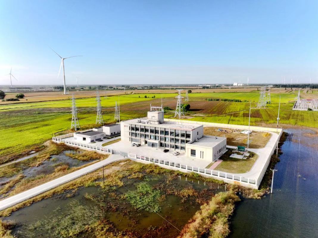
In modern power systems, electricity must be transported across vast distances—from generating stations to cities, industries, and homes. However, electrical energy generated at one voltage cannot be transmitted or used efficiently at that same level. This is where transformers become indispensable. They are strategically deployed at every critical junction of generation and transmission to adapt voltages for efficiency, compatibility, and safety. Without them, high-voltage transmission and controlled power flow across regions would be impossible. This article explores exactly where transformers are used in power generation and transmission, and how they support system performance.
Transformers are used in power generation at the generator terminal to step up voltage for transmission, and throughout the transmission network to interconnect grid segments, regulate voltage, and step down power for regional distribution. Key locations include generator step-up transformers (GSUs), interconnecting transformers at substations, and autotransformers in transmission corridors.
Each of these transformers has a specialized role, but all serve the common purpose of enabling efficient, large-scale energy delivery.
Transformers are essential at multiple points in both power generation and transmission systems.True
They step up voltage for transmission, interconnect different grid levels, and regulate power flow over long distances.
Transformers are only used in distribution systems and not needed for generation or transmission.False
Transformers are critical in generation and transmission stages for voltage transformation and system coordination.
Key Locations of Transformers in Generation and Transmission Systems
| System Segment | Transformer Type | Primary Function |
|---|---|---|
| Power Plant (Generator Output) | Generator Step-Up (GSU) Transformer | Converts 11–25kV generator voltage to 132–765kV transmission level |
| Power Station Switchyard | Station Transformer | Supplies station auxiliary power (HV → MV/LV) |
| Interconnecting Substations | Power or Auto Transformer | Links 400kV ↔ 220kV ↔ 132kV systems across regions |
| Regional Load Dispatch Substation | Step-Down Transformer | Reduces voltage for downstream sub-transmission (e.g. 220 → 66kV) |
| Tie-Line Grid Nodes | Phase-Shifting Transformer (PST) | Controls power flow direction and load sharing |
| Reactive Power Control Points | Shunt/Series Transformers, Booster Tx | Manages voltage stability and load balancing |
These transformers form a multi-voltage, multi-tier network that enables national or continental-scale grid operation.
1. Generator Step-Up Transformers (GSUs)
| Location | Between the generator terminal and the HV switchyard |
|---|---|
| Voltage Levels | 11–25 kV (input) → 132–765 kV (output) |
| Purpose | Increases voltage for long-distance transmission |
| Design | Three-phase, oil-immersed, copper-wound, often with on-load tap changer |
GSUs are critical for minimizing I²R losses during bulk power transmission.
2. Interconnecting Substation Transformers
| Function | Transfer energy between different grid voltage levels |
|---|---|
| Typical Voltage Range | 400 kV ↔ 220 kV ↔ 132 kV |
| Types Used | Autotransformers (preferred for efficiency) or two-winding transformers |
| Additional Role | Enable load flow control, fault isolation, and network flexibility |
These transformers serve as transmission system routers, connecting regions and balancing power demand.
3. Station Service Transformers
| Installed In | Power plant auxiliary systems (boilers, motors, control rooms) |
|---|---|
| Function | Steps down HV or MV to LV for internal power use |
| Voltage Example | 132 kV or 33 kV → 400 V/230 V |
| Design | Dry-type or oil-filled, smaller capacity (1–10 MVA) |
These units power the plant that powers the grid—an often overlooked but vital role.
4. Transmission Corridor Transformers
| Deployed At | Long-distance lines where two regional systems meet |
|---|---|
| Transformer Role | Voltage level match, phase balance, and power redirection |
| Special Types | Phase-shifting transformers (PST), booster transformers |
| Impact | Prevents loop flows, overloads, and congestion in cross-border links |
These transformers stabilize interregional grid interconnectivity.
5. Reactive Compensation Transformers
| Installed Near | Transmission substations and critical nodes |
|---|---|
| Function | Provide or absorb reactive power to regulate voltage |
| Types | Tertiary winding reactors, tap-regulating transformers |
| Grid Benefit | Prevents voltage collapse during peak demand or long-distance transmission |
These components ensure that voltage stays within ±5% tolerance range across the system.
Visual Summary: Transformer Placement Map
| Grid Level | Transformer Type | Purpose |
|---|---|---|
| Power Plant Output | GSU Transformer | Step-up for transmission |
| Plant Auxiliary Power | Station Transformer | Internal LV supply |
| Interregional Substation | Auto Transformer | Voltage matching and power routing |
| Long-Distance Corridor | Phase-Shifting Transformer | Control direction and magnitude of flow |
| Grid Connection to Substation | Step-Down Transformer | Reduce to sub-transmission level |
| Voltage Support Node | Tap-Changing/Booster Transformer | Reactive compensation and voltage control |
How Do Transformers Support Residential Electricity Use?
Most people rarely think about how the electricity that powers their lights, appliances, and devices gets to their homes—but at the heart of this quiet operation is a transformer. Without transformers, it would be impossible to deliver electricity safely and efficiently to residential neighborhoods. Grid voltages are far too high for direct use in homes, and current must be carefully regulated. Transformers solve this by stepping down high transmission voltages to usable levels. In this article, we explain exactly how transformers support residential electricity use, from pole to plug.
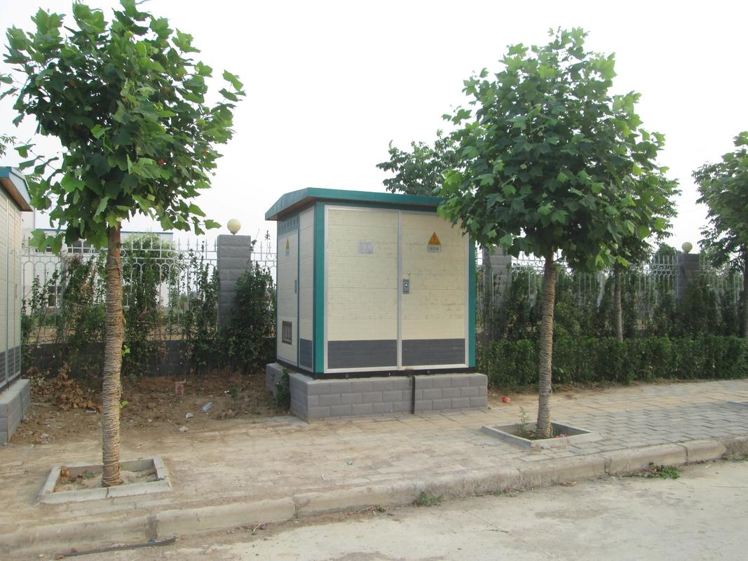
Transformers support residential electricity use by reducing high-voltage power from the distribution grid—typically 11kV or 33kV—to safe and usable levels like 230V (single-phase) or 400V (three-phase). This final step-down transformation occurs through pole-mounted or pad-mounted distribution transformers, ensuring households receive stable, safe, and regulated electricity.
This voltage transformation is essential for protecting appliances, reducing shock risk, and ensuring proper electrical performance at home.
Transformers reduce high-voltage electricity to levels suitable for home use.True
Transformers step down distribution voltages to 230V or 400V, which are safe and compatible with residential appliances.
Homes can safely receive electricity directly from 11kV transmission lines without a transformer.False
Direct high-voltage supply to homes is dangerous and would destroy household appliances; voltage must be stepped down first.
The Step-Down Process: From Grid to Home
| Stage | Voltage Level | Component Used |
|---|---|---|
| Distribution Line | 11kV or 33kV | Medium-voltage line (overhead or underground) |
| Final Distribution Transformer | 11kV → 230V/400V | Pole-mounted or pad-mounted transformer |
| Service Line to House | 230V single-phase (typical) | Underground or overhead service cable |
| Domestic Load | 230V sockets, lights, appliances | Internal wiring and breakers |
This last voltage step-down is the most important for residential safety and compatibility.
Types of Transformers Used in Residential Power Supply
| Transformer Type | Typical Installation | Common Features |
|---|---|---|
| Pole-Mounted | Utility poles in suburbs, towns | Oil-filled, compact, often 25–100 kVA |
| Pad-Mounted | Urban sidewalks, apartment areas | Ground-mounted, tamper-proof enclosure |
| Substation Transformer | Upstream at feeder level | Step-down to 11kV before final residential distribution |
Both types are designed to operate reliably outdoors, with overload protection and lightning arresters.
Safety Benefits of Residential Transformers
| Function | Safety Advantage |
|---|---|
| Voltage Reduction | Prevents direct exposure to high voltages |
| Grounding and Neutral Provision | Enables safe circuit design and shock protection |
| Surge Protection | Prevents spikes from damaging home electronics |
| Circuit Isolation | Limits fault propagation from one home to another |
Transformers not only deliver power but also protect your home and family from electrical hazards.
Voltage Stability and Power Quality
| Transformer Design Element | Power Quality Impact |
|---|---|
| On-load tap changers (OLTC) | Maintains voltage under fluctuating load conditions |
| Proper winding configuration | Minimizes harmonics and reduces electromagnetic interference |
| Low impedance | Supports voltage regulation and reduced voltage drop |
Even minor voltage drops can damage appliances—transformers stabilize voltage for continuous safe use.
Integration With Smart Grid and Renewable Energy
| Modern Feature | Residential Benefit |
|---|---|
| Smart metering compatibility | Enables accurate billing and energy monitoring |
| Bi-directional transformers | Allow solar-fed homes to export power back to the grid |
| Load balancing via transformer tap | Prevents outages and optimizes supply in real-time |
Newer transformer models are smart-grid ready, enabling efficient energy flow in both directions.
Transformer Ratings for Residential Use
| Home Type | Typical Transformer Size | Voltage Output |
|---|---|---|
| Single home (rural) | 10–25 kVA | 230V |
| Suburban block (5–10 homes) | 50–100 kVA | 230V (single-phase) / 400V (3-phase) |
| Apartment building | 100–315 kVA | 400/230V |
Proper sizing ensures adequate load handling and voltage stability without oversizing (which leads to inefficiency).
What Role Do Transformers Play in Commercial and Industrial Settings?
In commercial and industrial environments, the demand for electricity goes far beyond that of residential settings. Large machinery, HVAC systems, automation panels, data centers, and production equipment all require power at varying voltages and loads. If this power is not delivered efficiently, safely, and reliably, the consequences include downtime, damaged equipment, and financial loss. This is where transformers play an irreplaceable role—serving as voltage modulators, isolation devices, and power quality stabilizers tailored to the unique needs of these high-load environments.
Transformers in commercial and industrial settings step down medium-voltage power (typically 11kV or 33kV) to lower, usable voltages such as 415V, 400V, or 230V for equipment and facility use. They also provide galvanic isolation, manage load distribution, and stabilize voltage levels, ensuring safe and uninterrupted operation of machinery, systems, and critical infrastructure.
Whether it’s powering a factory floor, a shopping mall, or a high-rise building, transformers are the silent enablers of productivity and operational continuity.
Transformers in industrial settings reduce voltage and isolate circuits to power machines safely.True
Transformers step down incoming utility voltage and prevent faults from spreading, ensuring equipment receives proper voltage and protection.
Commercial facilities can operate large-scale electrical loads directly from high-voltage transmission lines without transformers.False
Commercial and industrial users require step-down transformers to adapt medium voltage to usable levels for equipment and lighting.
Common Transformer Applications in Commercial & Industrial Facilities
| Application Area | Voltage Input | Voltage Output | Transformer Type |
|---|---|---|---|
| Manufacturing Plant | 11kV / 6.6kV | 415V / 400V | Oil-immersed or dry-type |
| Data Center | 11kV | 415V / 230V | Cast resin (dry-type) |
| Shopping Mall / Hotel | 33kV / 11kV | 400V / 230V | Pad-mounted oil-immersed |
| Hospital / Laboratory | 11kV | 400V / 230V | Isolation transformer, dry-type |
| High-Rise Commercial Tower | 33kV / 11kV | 400V / 230V | Distribution transformer (compact) |
Each environment has unique voltage and safety requirements, and transformer selection is customized accordingly.
Key Roles of Transformers in Industrial and Commercial Power Systems
1. Voltage Transformation
Transformers allow facilities to receive high-voltage power from utilities (33kV or 11kV) and convert it to lower voltages suitable for electrical panels, lighting systems, and machinery.
- Typical conversion: 11kV → 415V/400V/230V
- Supports mixed 3-phase and single-phase loads
- Ensures power compatibility with local equipment
2. Power Isolation and Safety
Transformers provide galvanic isolation, separating internal facility circuits from the utility supply.
- Prevents voltage transients and ground loops
- Enhances worker safety in fault-prone or wet environments
- Common in hospitals, cleanrooms, and CNC operations
3. Voltage Stabilization and Load Regulation
Large loads like motors and compressors can cause voltage dips. Transformers with proper impedance and tap changers can:
- Absorb voltage transients
- Maintain steady output under load variation
- Extend equipment lifespan by preventing undervoltage damage
4. Load Management and Segmentation
Multiple transformers may be used within one facility to distribute load across zones:
- Transformer 1: Feeds motor control center (MCC)
- Transformer 2: Feeds lighting and HVAC panels
- Transformer 3: Serves data-sensitive loads with isolation
Segmentation enhances fault localization and simplifies maintenance.
Transformer Types Commonly Used
| Type | Typical Use | Advantage |
|---|---|---|
| Oil-Immersed Transformer | Outdoor substations in factories | High efficiency and thermal performance |
| Dry-Type Cast Resin Transformer | Indoor use in malls, offices, hospitals | Fire-safe and compact, less maintenance |
| Isolation Transformer | Labs, medical rooms, sensitive electronics | No conductive path between primary and secondary |
| Auto-Transformer | Large motors and HVAC startup voltage reduction | Lower cost and size for certain applications |
Transformer selection is based on:
- Environment (indoor/outdoor)
- Load sensitivity
- Fire safety requirements
- Harmonic considerations
Safety and Protection Features
| Feature | Purpose |
|---|---|
| Temperature Sensors (RTD) | Prevent overheating of windings |
| Overcurrent Protection | Disconnect load during faults |
| Surge Arresters | Protect against lightning or switching surges |
| Buchholz Relay | Detects internal faults in oil-filled transformers |
| Ground Fault Detection | Ensures proper insulation and protects staff/equipment |
These systems ensure transformers operate safely in mission-critical environments.
Typical Sizing for Industrial Applications
| Facility Type | Recommended Transformer Capacity |
|---|---|
| Small Commercial Block | 100–250 kVA |
| Medium-Sized Factory | 500–1,000 kVA |
| Large Industrial Plant | 2,000–5,000 kVA or multiple units |
| Data Center Tier III | 3,000–6,000 kVA with redundancy |
Proper sizing ensures optimal loading (usually 60–85%) and avoids overheating or derating.
How Are Transformers Used in Transportation Systems Like Railways?
Electric railway systems—whether for high-speed trains, metros, or freight corridors—require enormous amounts of power delivered with precision, consistency, and safety. Unlike static applications in buildings, transportation systems introduce continuous movement, long-distance transmission, and rapidly fluctuating loads. Transformers are the silent backbone of these systems, converting and regulating power for overhead lines, substations, signaling equipment, and locomotives. In this article, we explain how transformers are used in railway and transportation systems, and why their presence is essential to smooth and reliable train operations.
Transformers in transportation systems like railways are used to step down high-voltage grid power to traction voltages, provide power to overhead catenary systems, isolate and stabilize circuits, and enable long-distance power transfer through autotransformer-fed lines. They are installed in traction substations, along rail tracks, inside locomotives, and within signaling and station power systems.
Without transformers, electric trains could not operate safely, efficiently, or over long distances with consistent voltage control.
Transformers in railway systems step down high-voltage power to levels suitable for train operation and distribute it across the network.True
Transformers convert transmission voltage to traction voltage (e.g., 25kV AC) and ensure stable delivery to moving trains.
Railways do not require transformers because trains use their own power sources.False
Electric trains rely entirely on external power supplied through substations and overhead lines, which depend on transformers for voltage regulation.
Key Roles of Transformers in Railway Electrification
| Application Area | Transformer Type | Main Function |
|---|---|---|
| Traction Substations | Traction Power Transformer | Converts 132/110kV grid voltage to 25kV AC for train use |
| Along the Railway Line | Autotransformers (AT System) | Maintain voltage over long distances, reduce transmission losses |
| Inside Electric Locomotives | Onboard Traction Transformer | Steps down 25kV catenary voltage to motor drive voltage |
| Station Facilities | Distribution Transformer | Powers lighting, HVAC, escalators, and auxiliary equipment |
| Signaling Systems | Isolation or Control Transformer | Ensures stable, noise-free power for signal reliability |
Transformers are placed at multiple points to deliver, control, and protect electrical systems across the railway infrastructure.
1. Traction Substations – High Voltage Step-Down
| Location | Every 30–60 km along rail routes |
|---|---|
| Input Voltage | 132kV / 110kV (from national grid) |
| Output Voltage | 25kV AC (single-phase or split-phase for traction supply) |
| Transformer Type | Oil-immersed or dry-type traction transformer |
| Features | High thermal withstand, single-phase operation, tap changer |
Traction transformers are designed to handle unbalanced loads and high harmonics from electric trains.
2. Autotransformer Feeding System (AT Feeding)
| System Design | 2×25kV system with autotransformers spaced along the track |
|---|---|
| Function | Reduces voltage drop and return current in long rail segments |
| Installation | At intervals of 10–15 km, connected to neutral and supply lines |
| Benefit | Maintains consistent 25kV at train pantographs, even over 100+ km |
Autotransformers allow for longer intervals between substations and lower losses in return circuits.
3. Onboard Traction Transformers
| Installed In | High-speed trains, metro railcars, and EMUs (Electric Multiple Units) |
|---|---|
| Input Voltage | 25kV AC (collected from pantograph) |
| Output Voltage | Varies per motor controller, often 1.5–3kV |
| Features | Compact, vibration-resistant, lightweight, high-efficiency |
These transformers enable precise voltage delivery to traction motors, with built-in cooling and safety systems.
4. Auxiliary Power for Stations
| Function | Powers non-traction systems in railway stations |
|---|---|
| Voltage Conversion | 11kV or 6.6kV → 400V/230V |
| Systems Powered | Lights, air conditioning, elevators, signaling, fire alarms |
| Transformer Type | Dry-type or oil-type, low-capacity distribution transformers |
While often overlooked, these transformers are essential to station operations and passenger comfort.
5. Transformers for Signaling and Control Systems
| Location | Signal relay rooms, control centers, and trackside equipment |
|---|---|
| Type Used | Control or isolation transformers |
| Function | Ensures clean, interference-free power for relay logic and sensors |
| Design Focus | Low EMI, short-circuit protection, and consistent voltage regulation |
Signal transformers must be reliable, fail-safe, and tolerant to harsh environmental conditions.
Visual Summary: Transformer Deployment in Railway Systems
| Zone | Transformer Role | Voltage Levels |
|---|---|---|
| Power Grid Interface | Traction Transformer at Substation | 132kV → 25kV |
| Along Track | Autotransformer Boost System | 25kV/0V → Balanced rail voltage |
| Inside Train | Onboard Transformer for Drive System | 25kV → 1.5–3kV |
| Stations and Terminals | Auxiliary Transformer | 6.6/11kV → 400V/230V |
| Signal and Safety Equipment | Isolation/Control Transformer | 230V → 24V / 48V / 110V |
This layered deployment ensures that power is distributed intelligently across moving and static components of the railway ecosystem.
What Is the Application of Transformers in Renewable Energy Systems?
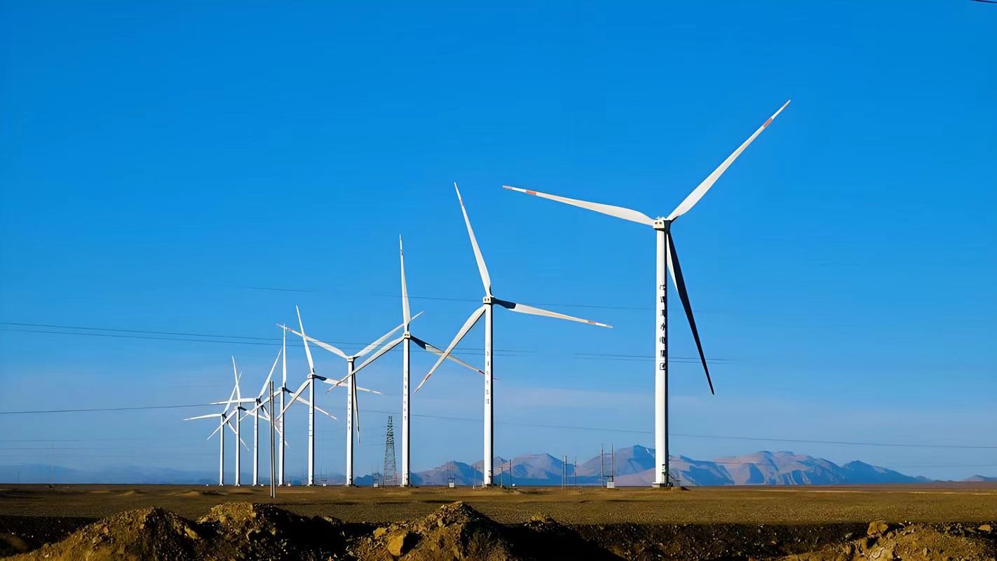
As global demand for clean energy continues to rise, solar, wind, and other renewable energy sources are playing an increasingly vital role in electricity generation. However, these renewable sources generate power at low or medium voltages, which are unsuitable for long-distance transmission or direct grid connection. Transformers are the essential interface that enables the safe, efficient integration of renewable energy into the power grid. From inverter step-up units at the source to large grid-tied substations, transformers ensure that renewable electricity can be delivered reliably and at the correct voltage.
Transformers in renewable energy systems are used to step up the low-voltage output from solar panels and wind turbines to medium and high voltages suitable for grid transmission. They also provide voltage regulation, system protection, and allow for efficient power export from decentralized renewable sources to centralized transmission networks.
Without transformers, power from renewables would remain trapped at the source—unable to contribute meaningfully to the grid or reach end users.
Transformers are essential in renewable energy systems to step up voltage for grid connection and transmission.True
Renewable energy is typically generated at low voltages, and transformers are required to increase this voltage for efficient grid integration.
Transformers are not needed in solar or wind farms since they use inverters.False
Inverters convert DC to AC, but transformers are still needed to raise the voltage to transmission or distribution levels.
Where Transformers Are Used in Renewable Energy Systems
| Location | Transformer Type | Function |
|---|---|---|
| Solar PV Plant (Inverter Output) | Inverter Transformer (Pad/Skid Mount) | Steps up voltage from 400–690V to 11–33kV |
| Wind Turbine Base | Generator Step-Up Transformer | Raises 690V turbine output to 11–33kV |
| Collector Substation | Power Transformer | Aggregates and steps up voltage to 132–220–400kV |
| Battery Energy Storage System | Isolation/Step-Up Transformer | Enables DC-AC conversion and grid compliance |
| Grid Interconnection Point | Grid-Tie Transformer | Matches transmission voltage and provides protection |
Each transformer is tailored for power flow, environmental conditions, and source-specific characteristics.
1. Solar PV Systems
| Voltage Output from PV Inverter | 400V – 690V (AC) |
|---|---|
| Transformer Role | Steps up to 11kV – 33kV |
| Transformer Type | Pad-mounted dry-type or oil-immersed |
| Special Features | High ambient temp rating, harmonic tolerance |
One transformer may serve a single inverter or multiple strings via a ring main unit (RMU) system.
2. Wind Energy Systems
| Turbine Generator Output | Typically 690V (AC) |
|---|---|
| Transformer Location | Inside nacelle or at tower base |
| Step-Up Voltage | 11kV – 33kV |
| Construction | Hermetically sealed or dry-type |
Offshore and large-scale wind farms use subsea transformers or containerized modules for environmental resilience.
3. Renewable Collector Substations
| Function | Consolidates energy from multiple sources |
|---|---|
| Voltage Conversion | 11/33kV → 66/132/220kV |
| Transformer Type | 3-phase oil-immersed power transformer with OLTC |
| Grid Integration | Connects to transmission or high-voltage distribution grid |
This is the most critical transformer in the system, acting as the interface with the utility grid.
4. Transformers in Battery Energy Storage Systems (BESS)
| Role | Isolation and step-up for bidirectional energy flow |
|---|---|
| Charging Voltage | Grid voltage stepped down via transformer |
| Discharging Voltage | Battery inverter output stepped up to match grid levels |
| Importance | Prevents ground loops, balances harmonic distortion |
Transformers here support both energy import and export, maintaining grid stability during charge/discharge cycles.
Environmental and Operational Considerations
| Design Element | Impact on Renewable Integration |
|---|---|
| Corrosion Resistance | Needed for coastal and offshore installations |
| Low-Loss Core Material | Reduces energy waste over long hours of daytime operation |
| Noise and EMI Shielding | Ensures compliance in residential and rural solar installations |
| Compact Construction | Fits within containerized or skid-mounted renewable platforms |
Transformers in renewables are often subject to higher environmental stresses, requiring ruggedized enclosures and low-maintenance designs.
Real-World Application: 50 MW Solar Farm
| System Component | Typical Voltage Level | Transformer Used |
|---|---|---|
| Inverter Output | 400–690V | 2.5MVA pad-mounted step-up transformer |
| MV Feeder | 33kV | RMU-connected collector transformer |
| Grid Interface | 132kV | Power transformer (OLTC) at substation |
The result is a seamless energy flow from sunlight to substation, fully enabled by transformers.
How Do Transformers Ensure Reliable Power in Critical Facilities Like Hospitals and Data Centers?
In hospitals, data centers, and other mission-critical environments, a momentary loss of power can lead to catastrophic outcomes—from medical device failures to data loss and system crashes. These facilities demand uninterrupted, clean, and stable electricity, often requiring tiered power protection and redundancy. Transformers play a central role in delivering this reliability. They regulate voltage, isolate critical systems, work alongside UPS and generators, and ensure that power is clean and consistent under all conditions. This article explains how transformers ensure reliable power in hospitals, data centers, and other high-dependency environments.
Transformers ensure reliable power in critical facilities by stepping down utility voltage to required levels, isolating sensitive systems from electrical disturbances, stabilizing voltage against load changes, and working with UPS and backup generators to deliver seamless power continuity. Special designs like isolation transformers, shielded dry-type units, and redundancy-configured transformers are commonly used in hospitals and data centers to ensure patient safety and data integrity.
Their reliability, low failure rate, and customization for sensitive loads make transformers a backbone of critical infrastructure power systems.
Transformers help maintain continuous and stable power in hospitals and data centers by isolating and regulating voltage.True
Transformers eliminate voltage fluctuations and isolate critical systems from surges and ground faults, supporting uninterrupted operation.
Critical facilities like hospitals can operate safely without transformers in their electrical systems.False
Without transformers, voltage would be unstable or unsafe for sensitive equipment, and there would be no isolation from grid disturbances.
Key Applications of Transformers in Critical Infrastructure
| Facility Area | Transformer Function | Typical Voltage Levels |
|---|---|---|
| Main Incoming Supply | Step-down from 11kV or 33kV to 400/230V | 33kV → 415V or 11kV → 400V |
| Power Distribution Panels | Voltage regulation and load balancing | 400V three-phase |
| Operating Rooms (Hospitals) | Isolation and interference protection | 230V single-phase or 400V 3-phase |
| Data Server Racks (Data Centers) | Clean, isolated power to avoid data loss | 208V/240V with grounded or isolated neutrals |
| UPS Interface | Voltage matching and bypass/transfer integration | 400V in/out |
| Emergency Power Backup | Generator-to-load voltage matching | 400V or 480V |
Transformers in these settings do more than just step down voltage—they maintain power integrity.
Specialized Transformer Types Used
| Transformer Type | Primary Function in Critical Settings |
|---|---|
| Isolation Transformer | Separates patient-connected or data-sensitive circuits from grid |
| Dry-Type Cast Resin | Fire-safe indoor use, high dielectric performance |
| Shielded Transformer | Blocks EMI/RFI, used near servers and imaging equipment |
| K-Rated Transformer | Handles non-linear loads with high harmonic content (UPS, IT loads) |
| Redundant Transformer Systems | Ensures power continues if one unit fails |
Hospitals use medical isolation transformers in operating rooms and ICU wards, while data centers rely on K-rated, shielded units near server banks.
Power Continuity Architecture in Critical Facilities
| System Component | Role of Transformer |
|---|---|
| Grid Connection Point | Step-down transformer ensures compatibility with facility voltage |
| Main Distribution Panel | Central transformer regulates load voltage for the facility |
| UPS System | Interfaces via transformer to manage charge/discharge flow |
| Generator Backup | Step-up or matching transformer enables proper generator feeding |
| Surge Protection | Transformers mitigate grid surges before sensitive electronics |
Transformers are often part of "dual-feed" or "2N redundant" systems, where two independent transformers feed the same load through A/B switching.
Safety and Compliance Advantages
| Standard/Requirement | Transformer Contribution |
|---|---|
| IEC 61558 (Isolation Transformers) | Ensures safe voltage in patient care areas |
| NFPA 70 (NEC for Hospitals/Data Centers) | Requires isolated power zones and proper grounding |
| TIA-942 (Data Center Design) | Specifies redundancy and EMI shielding for critical loads |
| ISO 13485 (Medical Equipment Safety) | Requires clean and isolated power for certified instruments |
Transformers help these facilities meet global regulatory standards for both electrical safety and operational resilience.
Example Use Case: Tier III Data Center Power System
| Power Flow Step | Voltage Conversion | Transformer Used |
|---|---|---|
| Grid Supply | 11kV → 415V | Oil-immersed step-down transformer |
| UPS System (Input & Output) | 415V ↔ 415V | K-rated isolation transformer |
| Server Hall Distribution Panel | 415V → 208V | Dry-type step-down with EMI shielding |
| Generator Backup Feeder | 400V → 400V bypass route | Matching transformer with load sharing |
All transformers are UPS-compatible, low-impedance, and fire-rated, optimized for clean and secure energy.
Operational and Redundancy Benefits
| Advantage | Explanation |
|---|---|
| Voltage Stability | Eliminates fluctuations that can crash servers or damage monitors |
| Isolation | Protects staff and electronics from electrical noise and surges |
| Redundancy | Supports uninterrupted operation during maintenance or failure |
| Load Adaptation | Balances single- and three-phase loads without imbalance |
| Fire Safety | Non-oil dry-type designs reduce combustion risk |
Transformers allow tiered power protection, meaning facilities maintain service even under partial system failure.
Conclusion
Transformers are found in virtually every corner of our daily lives—from the electricity we use at home to the systems that power industries, transportation, and renewable energy. Their ability to adjust voltage levels safely and efficiently makes them a backbone of modern electrical infrastructure. Without transformers, reliable and scalable electric power distribution would be impossible.
FAQ
Q1: Where are transformers used in real life?
A1: Transformers are used everywhere electricity flows, including:
Power generation stations
Transmission and distribution substations
Residential neighborhoods
Factories and commercial buildings
Hospitals and data centers
Electric vehicles and charging stations
Electronic devices and appliances
Q2: How are transformers used in homes?
A2: In homes, transformers:
Step down high-voltage electricity to 120/240V
Power low-voltage systems like doorbells and thermostats
Convert voltage in phone chargers and electronics
Ensure safe, stable voltage for household use
Q3: What are some industrial uses of transformers?
A3: In industries, transformers are used to:
Run heavy machinery at specific voltages
Distribute power efficiently across large facilities
Isolate circuits for protection
Supply power to production lines and control systems
Q4: Where are transformers found in public infrastructure?
A4: Public uses include:
Street lighting systems
Public transit systems (e.g., railway traction transformers)
Telecommunication towers
Utility substations in cities and rural areas
Solar and wind farms integrating power into the grid
Q5: Are transformers used in modern technologies?
A5: Yes. Transformers are essential in:
Smart grids with intelligent voltage control
Medical equipment for voltage isolation
Renewable energy systems for voltage matching
Electric vehicles for charging and onboard voltage regulation
References
"Real-Life Applications of Transformers" – https://www.transformertech.com/transformer-real-life-uses
"Where Are Transformers Used?" – https://www.electrical4u.com/applications-of-transformers
"Practical Use of Transformers in Power Systems" – https://www.powermag.com/transformer-applications-explained
"Everyday Examples of Transformer Use" – https://www.energycentral.com/c/ee/transformer-real-world-examples
"Transformers in the Modern Power Grid" – https://www.smartgridnews.com/transformer-grid-applications
"Transformers in Public and Private Sectors" – https://www.researchgate.net/transformer-usage-study
"PowerGrid: Where Transformers Work Daily" – https://www.powergrid.com/transformer-deployment
"ScienceDirect: Technical Use of Transformers in Real Life" – https://www.sciencedirect.com/transformer-usage-analysis